Page 1 of 12
CLUTCt
I
SECTION CL
CONTENTS
HYDRAULIC CLUTCH CONTROL
CLUTCH UNIT
..
SERVICE DATA AND SPECIFICATIONS (S DS 1
SPECIAL SERVICE TOOLS .
CL- 2
CL-10 cL- w
CL-12
Page 2 of 12
HYDRAULIC CLUTCH CONTROL
(08.1 2.58 -8 71
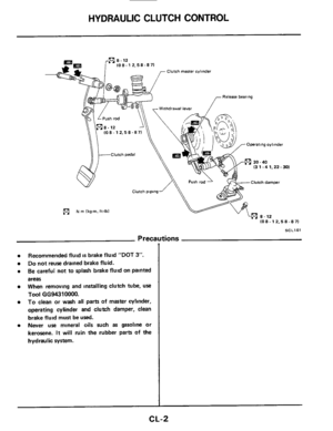
Clutch master cylinder
Release bearing
Omrating cylinder
I3 1.4 1,22 - 301
Clutch damper
(c1 N rn (kg-m. ft-lbl
(08.12.58 -8 71
SCL16I
Precautions
0
Recommended fluid is brake fluid "DOT 3'.
Do not reuse drained brake fluid.
Be careful not to splash brake fluid
on painted
areas
When removing and installing clutch tube,
use
Tool GG94310000.
To clean or wash all parts of master cylinder,
operating cylinder and clutch damper, clean
brake fluid must be
used.
Never use mineral oils such as gasoline or
kerosene.
It will ruin the rubber parts of the
hydraulic system.
CL-2
Page 3 of 12
HYDRAULIC CLUTCH CONTROL
Bleeding Procedure
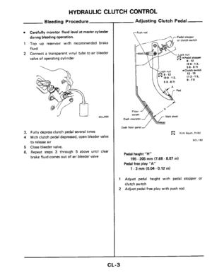
0 Carefully monitor fluid level at master cylinder
during bleeding operation.
1 Top up reservoir with recommended brake
fluid
2 Connect a transparent vinyl tube to air bleeder
valve of operating cylinder
3. Fully depress clutch pedal several times
4 With clutch pedal depressed, open bleeder valve
to release air
5 Close bleeder valve.
6. Repeat steps 3 through 5 above untll clear
brake fluid comes out of air bleeder valve
-- Adjusting Clutch Pedal
or clutch witch
108-12, ir--- u I 58-87)
Dash insulator
[)ash floor panel -/
(91 N rn Ikg-rn,ft-lb)
SCL162
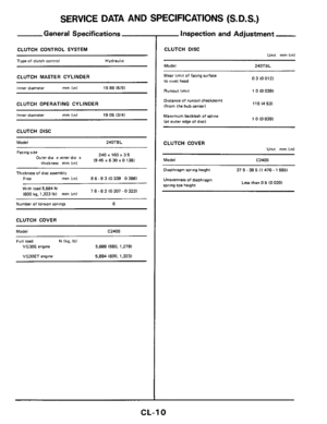
Pedal height "H"
Pedal free play "A"
195 - 205 mm (7.68 - 8.07 in)
1 - 3 mm (0.04 - 0.12 in)
1 Adjust pedal height with pedal stopper or
2
clutch switch
Adjust pedal free play with push rod
CL-3
Page 4 of 12
l7-13
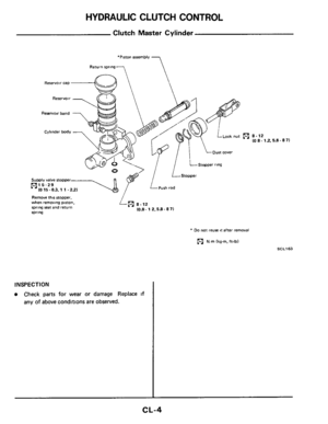
.pa/uasqo ale suoiaipuo3 aAoqe 40 hue
41 axidad a6eluep JO JeaM JOJ sued y3aq3 0
N01133dSNI
(L 8
Page 5 of 12
HYDRAULIC CLUTCH CONTROL
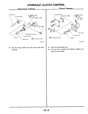
Operating Cylinder
Bleeder rrew Push rod
oust cover 10 7 - 0 9, 5.1 - 6 51
(3.1 - 4 1.22.30)
Operating cylinder
piston cup N m (kg-m. ff-lb)
SCL164
e Do not reuse piston cup and dust cover after
removal
- Clutch Damper
Pmon CUP
N m Ikg-m. ft-lbl Piston
SCL165
0
0
Do not reuse piston cup
Do not let oil touch the damper rubber as It
will ruin the rubber
CL-5
Page 6 of 12
HYDRAULIC CLUTCH CONTROL
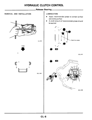
Releasc
REMOVAL AND INSTALLATION
CL145
.
Press
SCL166
'earing
LUBRICATION
Apply recommended grease to contact surface
and sliding surface
A small amount
of recommended grease should
be applied
7:
'I *-
Pack this recess e.
.'. *-
? _-
c=
SCL167
c=
CL-6
Page 7 of 12
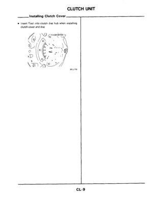
CLUTCH UNIT
Clutch Unit
-1 Slight burn or discoloration of Contact surface
with Clutch disc can be fixed by polishing with emery paper
mar drwe shaft does not adhere to clutch d!x
Clutch couer'l
SCL158
WARNING:
Clean away clutch disc dust using a dust collector
after cleaning with
a cloth. Do not use compressed
air.
CL-7
Page 8 of 12
CLUTCH UNIT
Inspecting Clutch Cover
I
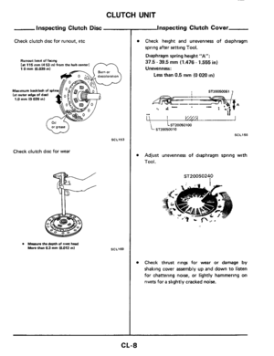
Inspecting Clutch Disc
Check clutch disc for runout, etc
Runout lam* of facq [a 115 mm 14 53 tnl from the hub center1 IO mm (0.039 in1
Maximum backlash of spit (at outer edge of dml 1.0 mm IO 039 in1
SCL153
Check clutch disc for wear
0 Measurn the depth of rim head More than 03 mm (0.012 mt SCL169
Check height and unevenness of diaphragm
spring after setting Tool.
Diaphragm spring height “A”:
37.5 - 39.5 mm (1.476 - 1.555 in)
Unevenness:
Less than 0.5 mm (0 020 in)
ST20050051 7
LST20050100 ST20050010
SCL155
Adjust unevenness of diaphragm spring with
Tool.
ST2005024,O
Check thrust rings for wear or damage by
shaking cover assembly up and down to listen
for chattering noise, or lightly hammering on
rivets for
a slightly cracked noise.
CL-8


Operating cylinder
piston cup N m (kg-m. ff-lb)
SCL164
e Do not reuse pi")


