Page 2 of 77

GENERAL SERVICING
Removal & Installation
Precautions
Location
When removing or installing various parts, place a cloth or padding onto the vehicle body to prevent
scratches.
Handle trim, molding, instruments, grille, etc carefully during removing or installation Be careful not to
soil or damage them.
Apply sealing compound where necessary while installing parts
When applying sealing compound, be careful that the sealing compound does not protrude from parts
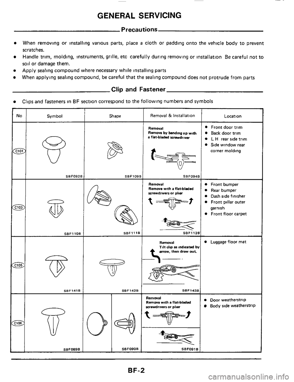
Clip and Fastener
Clips and fasteners in BF section correspond to the following numbers and symbols
Removal Remove by bending up wm~ a flat-bladed xrmdrava
Symbol
F 0 Front door trim
0 Back door trim
0 L H rear side trim
0 Side wlndow rear
;N SBF092E SBFO948
Removal Remove with a flat-bladed xrawdrivarr or plm
t
1OB -
0 Front bumper
R~~~ bumper
0 Dash side finisher
0 Front pillar outer
0 Front floor carpet
garnish
SBF1418
jT
SBFO89B
Shape
SBFlOP
SBFlllf
SBF142B
I
SBFO9OB
SBF112B
Removal 0 Luggage floor mat Tilt clip as mdtcated by arrow. then draw out
0 Door weatherstrip Removal Remwe with a fiat-bladed rsrewdrnarr 0. pimr Body side weatherstrip
‘T’ I
BF-2
Page 6 of 77

BODYENDANDDOOR
When removing and installing hood or back door, place a cloth or other padding on hood or back door
corners to avoid scratching vehicle body
When removing clip or fastener,
refer to CLIP & FASTENER.
Apply sealing compound where necessary when installing parts
Front End
Hood adjustment Adjust at hinge portion
Hood lock adjustment After adjusting, check hood lock control operation Apply a coat of grease to
hood locks engaging mechanism
Hood opener
Do not attempt to bend cable forcibly. Doing so increases effort required to unlock hood.
Bumper fascia.
It is made of plastic, so do not use excessive force and take care to keep oil away from it
When adjusting or removing/installing hood or removing/installing hood switch, check theft warning sys-
tem operation
WARNING:
a. Be careful not to scratch hood stay when installing hood. A scratched stay may cause gas leakage.
b. The contents
of the hood stay are under pressure. Do not take apart, puncture, apply heat or allow fire
near It.
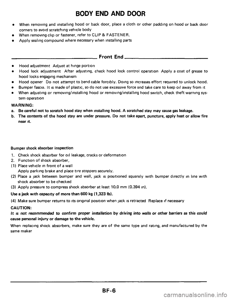
Bumper shock absorber inspection
1. Check shock absorber for oil leakage, cracks or deformation
2. Function of shock absorber,
(1) Place vehicle in front of a wall
(2) Place a jack between bumper and wall, jack is positioned squarely with bumper directly in line with
(3) Apply pressure to compress shock absorber at least 10.0 mm (0.394 in).
Use a jack with capacity of more than 600 kg (1,323 Ib).
(4) Make sure bumper returns to its original position when jack is retracted Replace if necessary
CAUTION:
It IS not recommended to confirm proper installation by driving into walls or other barriers as this could
cause personal injury
or damage to the vehicle.
When replacing shock absorbers, make sure they
are of the same type and rating, and manufactured by the
same maker
Apply parking brake and place tire stoppers securely.
shock absorber
to be checked
BF-6
Page 8 of 77
BODY END AND DOOR
Rear End
Back door adjustment. Adjust at hinge for proper back door fit
Lock Adjust lock
so that it is in the center of the striker. After adjusting, check back door lock opera-
tion Bumper fascia
It is made of plastic, so do not use excessive force and take care to keep oil away from it.
When adjusting or removing/installing back door or removing/installing back door lock system, check
theft warning system operation.
WARNING:
a. Be careful not to scratch back door stay when installing back door. A scratched stay may cause gas
leakage.
b. The contents of the back door stay are under pressure. Do not take apart, puncture, apply heat or allow
fire near
it.
BF-8
Page 76 of 77
BODY ALIGNMENT
Underbody (Cont'd)
Coordinates mm (in) Hole dia
rnm (in)
13(051)
15 (0 59)
18 (071)
13 (051)
Detailed points Points
"X" "V"
Hole for front air
spoiler mounting 385 0
(15 161
-585 0
(-23 03)
388 0
(1 5 28)
Hole for water
drainage 380 0
(14 961
435
0
(17 131
255
0
(1004)
-
-
251 5
(9 90)
750
0
129 53)
1,500 0
(59 06)
361 6
114 24)
263
6
(10 38)
261
0
(10 28)
2 seater
model
2,800
0
(11024)
2+2 seater
model
3,000
0
(11811)
Hole for locating
418 5
(16 48) 528 8
(20 82) 00 13 (0 51 At under ride of member
2 seater
model
3,060
0
(120 47)
!+2 seater
model
3,260
0
(1 28 35)
Hole for rear
bumper mounting 418 5
(1648) 523 8
(20 62) 15 (0 59)
13(051)
SBF427E
FR
c3
SBF428E
r Front side member
Hole for mounting
tension rod bracket
on underside of
front crossmember
271 0
(1067)
-
400 0
I1 5 751
-465.0
(-1831)
-10 0
(-0 394)
325 5
(1281)
422 0
(16.61)
Hole for locating on
front suspension
member mounting
portion
(Underside of front
side member)
00 16 (0 63)
BF-76