Page 17 of 25

12Disconnect the wiring from the bulb, then
release the spring clip and withdraw the bulb.
Do not touch the bulb glass.
13Refitting is a reversal of removal.
Front direction indicator lamps
Models up to 1987
14Remove the lamp unit.
15Twist the bulbholder anti-clockwise and
withdraw it from the rear of the lamp. The bulb
is a bayonet fit in the bulbholder (see
illustration).
16Refitting is a reversal of removal.
Models from 1987
17Remove the lamp unit.
18Release the bulbholder by pressing it and
turning clockwise, then withdraw the bulb
from the bulbholder (see illustration).
19Refitting is a reversal of removal.
Front direction indicator side
repeater lamps
Models up to 1987
20To improve access, turn the steering onto
full lock.
21Remove the relevant wheel arch liner.
22Working under the wheel arch, twist the
bulbholder anti-clockwise and withdraw it
from the lamp. The bulb is a push-fit in the
bulbholder.
23Refitting is a reversal of removal.
Models from 1987
24Remove the lamp unit. 25Twist the bulbholder anti-clockwise to
remove it from the lamp. The bulb is a push-fit
in the bulbholder.
26Refitting is a reversal of removal.
Front foglamps
27Remove the foglamp.
28On models up to 1987, remove the bulb
cover from the rear of the lamp, then release
the two spring clips, disconnect the wiring and
withdraw the bulb. Do not touch the bulb glass.
29On models from 1987, release the spring
clip and pull the bulb from the bulbholder. Do
not touch the bulb glass (see illustration).
30Refitting is a reversal of removal.
Rear lamp unit
Saloon and Hatchback models
31Working inside the luggage compartment,
press the plastic retaining tab and remove the
bulbholder assembly. The bulbs are a bayonet
fit in the bulbholder (see illustrations).
32Refitting is a reversal of removal.
Estate models
33Working inside the luggage compartment,
turn the retaining tabs a quarter-turn and
remove the rear side trim panel cover.
34Push out the retaining tabs and withdraw
the bulbholder. The bulbs are a bayonet fit in
the bulbholder.
35Refitting is a reversal of removal.
P100 models
36Remove the two securing screws and
detach the rear lamp wiring cover from the
side of the cargo area. 37Working through the cargo area aperture,
unscrew the two wing nuts and remove the
rear lamp cover.
38Twist the relevant bulbholder anti-
clockwise to remove it from the lamp. The
bulb is a bayonet fit in the bulbholder.
39Refitting is a reversal of removal, but
ensure that the wiring protective sheath is
seated correctly in the opening in the lamp
cover.
Rear number plate lamp
Saloon, Hatchback and Estate models
40Remove the lamp unit.
41Twist the bulbholder anti-clockwise to
remove it from the lamp. The bulb is a push-fit
in the bulbholder (see illustration).
42Refitting is a reversal of removal.
Body electrical system 13•17
13
48.15 Removing a front direction indicator
lamp bulb - models up to 1987
48.31b Removing a bulb from the rear lamp
bulbholder - Saloon and Hatchback
models48.31a Press the plastic retaining tab to
release the rear lamp bulbholder assembly
- Saloon and Hatchback models48.29 Front foglamp bulb retaining spring
clip - models from 1987
48.18 Removing a front direction indicator
lamp bulb - models from 1987
48.11 Auxiliary driving lamp bulb location -
models from 198748.9 Withdraw the auxiliary driving lamp
bulb from the headlamp unit -
models up to 1987
Page 18 of 25

P100 models
43Pull the lamp cover from the rubber
housing to expose the bulb. The bulb is a
bayonet fitting in the bulbholder.
44Refitting is a reversal of removal.
1Disconnect the battery negative lead.
Switches
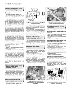
2Prise the switch from its location using a
thin-bladed screwdriver, and disconnect the
wiring plug (see illustration).
3Refitting is a reversal of removal.
Operating motors
4Remove the window regulator.
5Remove the three securing bolts, and
withdraw the motor from the regulator
assembly (see illustration).
6Refitting is a reversal of removal, but ensure
that the drive gear is correctly meshed with
the regulator.
Note:If a central locking solenoid or motor is
to be renewed due to jamming or overheating,
the central locking relay must be renewed atthe same time even if it is believed to be
working correctly. Before starting work on the
central locking system, unlock all the doors
and the tailgate/boot. Make sure that the keys
are outside the vehicle before reconnecting
the battery on completion of work.
Operation
Models up to 1987
1The central locking system is activated by
turning the key in the driver’s door lock, and
the locks are operated by solenoids.
Models from 1987
2The system is activated by turning the key
in either of the front door locks, and the locks
are operated by electric motors.
Removal and refitting
3Disconnect the battery negative lead.
Models up to 1987
Switch (driver’s door lock)
4Remove the door lock.
5Remove the two securing screws, then
withdraw the switch from the lock assembly
and disconnect the wiring plug.
6Refitting is a reversal of removal, but ensure
that the cut-out in the switch lever engages
with the lock lever (see illustration).
Solenoids (passenger and rear door locks)
7Remove the door lock (see illustration).
8Remove the two securing screws, then
disconnect the solenoid operating rod and thewiring plug and withdraw the solenoid from
the lock assembly.
9Refitting is a reversal of removal.
Solenoid (tailgate lock)
10Open the tailgate and remove the trim
panel.
11Disconnect the solenoid wiring plug and
earth lead, and the operating rod, then
remove the two securing screws and
withdraw the solenoid from the tailgate(see
illustration).
12Refitting is a reversal of removal.
Models from 1987
Motors (door locks)
13Remove the door inner trim panel.
14Remove the retaining screws and
disconnect the wiring plug and the motor
operating rod, then withdraw the motor from
the door.
15Refitting is a reversal of removal.
Motor (tailgate and boot lid locks)
16Open the tailgate/boot lid and where
applicable remove the trim panel.
17Remove the retaining screws and
disconnect the wiring plug and the motor
operating rod, then withdraw the motor from
the tailgate/boot.
18Refitting is a reversal of removal.
Models from 1990
Motors (door locking)
19On models from 1990, the door locking
motors are incorporated in the door lock units
(see illustrations).
20To remove a motor, first remove the door
lock.
50Central door locking
components - operation,
removal and refitting
49Electric window components
- removal and refitting
13•18Body electrical system
48.41 Removing a rear number plate lamp
bulb - Saloon, Hatchback and Estate
models49.5 Electric window motor securing bolts
(arrowed)
50.7 Central door locking assembly -
models up to 1987
A Solenoid
B Door ajar switch (not fitted to all models)
50.6 Driver’s door central locking switch -
models up to 1987
A Switch lever cut-out
49.2 Disconnecting the wiring plug from a
centre console-mounted electric window
switch - models from 1987
50.11 Removing a tailgate lock solenoid -
Hatchback models up to 1987
Page 19 of 25

21Remove the two securing screws, and
detach the motor from the lock assembly.
22Refitting is a reversal of removal, ensuring
that the motor operating rod engages with the
lock lever.
Note: The alarm system has a self-diagnosis
function, which allows a Ford dealer to carry
out fault diagnosis, using suitable specialist
equipment. In the event of a problem with the
alarm system, it is advisable not to tamper
with the components until appropriate fault
diagnosis has been carried out.Location
1From 1990, certain models are fitted with
an anti-theft alarm(see illustration).
2The alarm system consists of a control
module mounted behind the driver’s side
facia; trip switches fitted to the doors,
tailgate/boot lid, and bonnet; activating
switches fitted to the front door locks; an
additional horn mounted at the bulkhead next
to the battery and an indicator light mounted
on the top of the facia.
Module - removal and refitting
3Disconnect the battery negative lead.
4Release the carpet trim panel from under
the driver’s side facia. 5Reach up behind the facia and locate the
control module. Release the plastic retaining
clips using a screwdriver, and lower the
module.
6Disconnect the wiring plug and withdraw
the module.
7Refitting is a reversal of removal.
Removal
1Disconnect the battery negative lead.
2Remove the seat.
3Remove the seat cushion trim or backrest
trim as necessary.
4Note which way round the pad is fitted,
then remove the wire clips and adhesive tape
which secure it to the seat. Retrieve the tie-
rod and fit it to the new pad.
Refitting
5Fit the new pad with the thermostat facing
the cushion foam(see illustration).Secure
the pad with wire clips and tape, making sure
that it is not too tight - it must be able to flex
when sat on.
6Refit the cushion or backrest trim, as
applicable, being careful not to trap or kink
the pad.
7Refit the seat, reconnect the wiring and
check the pads for correct operation.
52Seat heating pad - removal
and refitting
51Anti-theft alarm - location,
removal and refitting
Body electrical system 13•19
13
50.19b Rear door central locking motor
securing screws (arrowed) -
models from 199050.19a Front door central locking motor
securing screws (arrowed) -
models from 1990
51.1 Anti-theft alarm
system components
A Tailgate/boot lid
switch
B Control module
C Horn
D Bonnet switch
E Door switch
F Activating switch
Page 20 of 25

1On models fitted with an electric aerial,
disconnect the battery negative lead.
Saloon and Estate models
2Remove the right-hand side trim panel from
the luggage compartment.
3Working outside the vehicle, unscrew the
nut and remove the spacer and seal from the
base of the aerial.
4Working inside the luggage compartment,
either unscrew the aerial bracket securing
screw and slide the bracket from the aerial
tube, or pull the base of the aerial from the
rubber bush in the bracket, as applicable (see
illustration).
5Ensure that the aerial is fully retracted, then
pull it through the hole in the bodywork into
the luggage compartment (see illustration).
6The aerial lead may be a push-fit in the
base of the aerial, or may be secured by a
knurled nut. Disconnect the aerial lead and
where applicable, disconnect the wiring from
the electric motor. Note that the aerial lead
runs through the roof. If it is necessary to
renew the lead, it may prove easier to leave
the old lead in place and run a new one under
the carpet. Follow existing wiring runs where
possible.
7Refitting is a reversal of removal.
Hatchback models
8Remove the right-hand rear seat side
cushion.
9Remove the rear parcel shelf.
10On “high specification” models, lift the
seat catch release lever, push out the pin
securing the link rod to the lever and
disconnect the link rod.
11Remove the securing screws from the rear
parcel shelf support (nine screws on models
up to 1987, eight screws from 1987 onwards).
Remove the rear parcel shelf support.
12Remove the side trim panel from the
luggage compartment.
13Proceed as described in paragraphs 3 to
7 inclusive.
P100 models
14Pull off the plastic trim cover and unscrew
the aerial securing nut.
15Withdraw the aerial assembly, and
carefully prise the base seal from the roof
panel.
16The aerial lead runs across the roof panel
under the headlining, and down the right-hand
front pillar to the radio unit. Renewal is
straightforward, but the front section of the
headlining must be released for access and a
length of string should be tied to the end of
the aerial lead before removal to aid routing
when refitting.
17The aerial rod can be renewed by simply
unscrewing it from the base.
18Refitting is a reversal of removal.
1Disconnect the battery negative lead.
Saloon models
2Remove both rear seat side cushions.
3Remove the securing screws and withdraw
the rear parcel shelf.
4Make a note of the wiring connections for
use when refitting, then disconnect the wiring,
remove the two securing screws, and
withdraw the amplifier unit (see illustration).
5Refitting is a reversal of removal.
Hatchback models
6Unclip the tailgate trim panel.
7Remove the amplifier bracket securing
screws, and withdraw the amplifier through
the tailgate panel aperture (see illustration).
8Make a note of the wiring connections for
use when refitting, then disconnect the wiring
and remove the amplifier unit.
9Refitting is a reversal of removal.
Estate models
10Unclip the tailgate trim panel.
11Make a note of the wiring connections for
use when refitting, then disconnect the wiring,
remove the four securing screws, and detach
the loudspeaker/amplifier bracket assembly
from the tailgate (see illustration).
12Refitting is a reversal of removal.
1Disconnect the battery earth lead.
Facia panel-mounted speakers
Upper
2Prise the speaker grille from its four
retaining clips in the facia using a thin-bladed
screwdriver.
3Remove the four securing screws,
disconnect the wiring, and pull the
loudspeaker from the facia panel.
4Refitting is a reversal of removal.
55Loudspeakers - removal and
refitting54Integral heated rear
window/radio aerial amplifier
- removal and refitting
53Radio aerial (exterior-
mounted) - removal and
refitting
13•20Body electrical system
52.5 Seat heating pad
Thermostat (arrowed) must face foam53.5 Removing an electric aerial -
Saloon model
54.7 Integral heated rear window/radio
aerial amplifier bracket securing screws
(arrowed) - Hatchback models54.4 Integral heated rear window/radio
aerial amplifier securing screws (arrowed)
- Saloon models
53.4 Pull the base of the aerial from the
rubber bush (arrowed)
Page 21 of 25

Lower
5Remove the lower facia panel.
6Remove the four securing screws,
disconnect the wiring, and pull the
loudspeaker from the facia panel.
7Refitting is a reversal of removal.
Rear parcel shelf-mounted
speakers
Saloon models
8Working in the luggage compartment,
remove the single securing screw, then lift the
loudspeaker into the passenger compartment
and disconnect the wiring. Withdraw the
loudspeaker.
9Note that it is important not to disturb the
loudspeaker mounting gasket or retainer.
10Refitting is a reversal of removal, but
ensure that the wiring does not touch the
retainer, shelf, or speaker, to prevent any
audible rattles.
Hatchback models
11Working under the parcel shelf, remove
the four securing screws, disconnect the
wiring, and withdraw the loudspeaker.
12Refitting is a reversal of removal.
Door-mounted speakers
13Remove the door inner trim panel.
14Remove the four securing screws, then
withdraw the loudspeaker from the door and
disconnect the wiring. Remove the
loudspeaker.
15Do not remove the loudspeaker from the
moulding, as the two are a sealed assembly.
16Refitting is a reversal of removal.
Tailgate-mounted speakers -
Estate models
17Remove the tailgate trim panel.
18Remove the four securing screws,
disconnect the wiring and withdraw the
loudspeaker. Note that on models with an
integral heated rear window/radio aerial, the
aerial amplifier unit is combined with one of
the loudspeaker units.19Refitting is a reversal of removal.
High frequency units
20These units are used to reproduce high
frequencies only, and incorporate an
electronic filter network which must not be
disconnected or bypassed. The units are
located in the lower facia panels.
21The removal and refitting procedure is as
described for the lower facia panel-mounted
loudspeakers earlier in this Section, but take
care not to damage the extremely fragile
speaker cones.
Removal
1Some “high specification” models are fitted
with an audio power amplifier, which is
mounted as a separate unit beneath the radio/
cassette unit. To remove the unit proceed as
follows.
2Disconnect the battery negative lead.
3Remove the two screws under the top edge
of the power amplifier unit.
4Slide the unit forwards from the facia panel,
until the wiring plugs can be disconnected.
Disconnect the wiring plugs and remove the
unit.
Refitting
5Refitting is a reversal of removal.
Standard fixing
1Disconnect the battery negative lead.
2Pull off the two control knob assemblies.
3Release the trim panel by unscrewing the
two securing nuts from the control spindles.
Remove the trim panel.4Using a hooked instrument, pull the
mounting plate securing tangs towards the
centre of the radio/cassette player, then slide
the unit forwards from the facia panel (see
illustration).
5Disconnect the wiring plugs and the aerial
lead, then remove the unit.
6Remove the plastic support bracket from
the rear of the unit, and unscrew the nuts and
washers from the control spindles to remove
the mounting plate from the front of the unit.
7Refitting is a reversal of removal.
DIN fixing
8An increasing number of radio/cassette
players have DIN standard fixings. Two
special tools, obtainable from in-car
entertainment specialists, are required for
removal.
9Disconnect the battery negative lead.
10Insert the tools into the holes in the front
of the radio/cassette player and push them
until they snap into place. Pull the tools
outwards to release the unit (see illustration).
11Pull the unit forwards and disconnect the
wiring plugs and the aerial lead. Remove the
unit from the facia panel.
12To refit the radio/cassette player,
reconnect the wiring and the aerial lead, then
simply push the unit into its bracket until the
retaining lugs snap into place.
Each wiring diagram covers a particular
system of the appropriate vehicle; as
indicated in each caption. Carefully read the
Key to each diagram before commencing
work.
58Wiring diagrams - general
information
57Radio/cassette player -
removal and refitting
56Radio/cassette player power
amplifier - removal and
refitting
Body electrical system 13•21
13
57.10 Removing a radio/cassette player
using special tools - DIN fixing57.4 Radio/cassette player securing tangs
(arrowed) viewed from the rear of the unit -
standard fixing54.11 Loudspeaker/integral heated rear
window/radio aerial amplifier bracket
securing screws (arrowed) - Estate models
Page 22 of 25
13•22Wiring diagrams
Notes, tables, wire colours and key to wiring diagrams. Models up to 1987
Page 23 of 25
13
Wiring diagrams 13•23
Key to wiring diagrams (continued). Models up to 1987
Page 24 of 25
13•24Wiring diagrams
Internal connection details. Models up to 1987
Klocka


. Models up to 1987")
