1984 Citroen CX Temperature
[x] Cancel search: TemperaturePage 109 of 394

Downloaded from www.Manualslib.com manuals search engine COLD START INJECTOR
When the engine is cold, fuel settles on the inlet distribution chamber, and on the cylinder walls. Therefore, the
quantity of fuel which mixes with the inlet air is smaller than in an engine which has reached normal running
temperature. The mixture thus obtained will not ignite.
The cold-start injector enriches the mixture in each inlet duct by vaporizing fuel in the inlet manifold. However,
it only comes into operation when the starter motor is actuated, and when a thermal switch located inthe engine
coolanthas simultaneously closed the circuit.
‘A helicoidal spring compresses the mobile core of,the electro-magnet and its seal fuel cannot pass through.
When the magnetic core is attracted, the injector seat is freed-off, the fuel flows past the core. and.reached the
spiral effect injector, which injects the fuel, simultaneously giving it a spiral motion, and vaporizing it very finely. ‘THERMAL SWITCH
The thermal switch cuts out the operation of the cold-start injector when the temperature of the engine reaches
ir 35” C,,For any temperature below t 35’ C, the thermal switch limits the duration of injection. The maximum
duration is approximately 7.5 sets. at - 20’ C. Duration of injection is reduced as temperature increases
The variation in duration, determined by the thermal switch,.is obtained by means of a bi-metallic strip heated
by an electrical resistance. The bi-metallic strip cuts out the circuit according to the temperature reached after
it has heated for a certain amount of time.
Page 112 of 394

Downloaded from www.Manualslib.com manuals search engine OPERATION No MA.IE. 144-00 : Chnract~~ristics o/ the H I,-jctrortic P dectrnr~ir
/i/c,1 iujcctim splcm. Op. MA.IE. 144-00 17
SUPPLEMENTARY AIR CONTROL ( 1 ) :
I’ / -...’ , _, ._,, ! .’ ! . .
At idling speed and when cold, the engine must produce more torque so as to counteract increased resistance
caused by friction. In addition to an enriched air fuel mixture, the engine also needs, when starting from cold
and during the warming-up period, to be supplied with supplementary air. The E.C.U. compensates for this
supplementary air by providing more fuel; the engine therefore has a larger amount of mixture at its disposal
to reach normal running temperature. The supplementary air control fitted in parallel with the throttle butterfly
supplies the supplementary air. The supplementary air control is heated only when the engine is running, and
its heater winding is supplied electrically as long as the ignition is switched on.
The location of the supplementary air control ‘on the engine block was selected for its good heat transfer charac-
teristics, and so as to subject the unit to the changing ambient temperature of the engine.
The opening section of the supplementary air control is automatically .adjusted according to the temperature, so
that the required idling speed is maintained regardless of engine temperature. When the latter increases, the air
channel is gradually reduced, until it is completely closed when the coolant temperature reaches approximately
+ 60” C. ->.:.. .-. : --.
,
The supplementary air control is situated at a representative spot fo.r engine running temperature. A bi-metal
spring actuates a rotary valve thereby altering the size of the air passage. Electric heating has the advantage
of allowing the. supplementary air to be adjusted at pre-set times. SWITCH ON THROTTLE BUTTERFLY SPINDLE :
,‘1 3 >_
The switch on the throttle butterfly spindle contains two contacts the idling speed contact, and the.full load contact.
The control contact, which.slides along a slot, closes the idling speed contact or the full load contact for a given
position of ‘the butterfly. The’ E.C.U. analyses the signals received so as to adjust the duration of injection.
Page 131 of 394

Downloaded from www.Manualslib.com manuals search engine Ill. CHECKING AND ADJUSTING
1
. Energizing the system ..................................................................................................................
2. ,Fuel pump feed ( on operating the starter ) .............................................................................
3. Fuel pump feed ( with engine running ) ...................................................................................
4. Supplementary air control ...........................................................................................................
5. Air-flow sensor ............................................................................................................................
6. Resistors and injectors ................................................................................................... . ........
7. Water temperature sensor ............................................................................................................ .
Dingram 7
8. Air temperature sensor ...............................................................................................................
9. Cold-start injector, and thermal switch ...................................................................................
10. Switch on throttle butterfly spindle ( idling speed function ) ............................................ 11
Switch on throttle butterfly spindle ( maximum power function ) ...................................... 12.
E.C.U: ......................................................................... ..~ ............................................................... . . Diagram 1 I ANNEXE : A
: Checking the ignition .................................................................................. Page 25 B
: Checking the air circuit ................................................................................ Page 26
C : Checking the fuel system and the fuel pressure ........................................... Page 27 D
: Adjusting the idling speed and the exhaust emission .............................. Page 28 NOTE
: On the wiring harness for the injectors, the numbers of the terminals on the E.C.U. terminal board are
visible on the rear section. after having withdrawn the casing secured by the end screw.
Page 135 of 394

Downloaded from www.Manualslib.com manuals search engine Op. MA.IE 444-O 15
3. Fuel pump feed ( with engine running ) : ( DIAGRAM 3 )
- Disconnect the E.C.U.
- Disconnect from the air-flow sensor the air hose to the butterfly housing
- Switch on the ignition:
- Actuate the air-flow sensor flap by hand’ when the petrol pump contact closes the pump should be heard
working.
If not, test the circuit using a
battery operated ohmmeter, without forgetting to test between terminal G 36 ))
on the air-flow sensor and terminal H 20 .)) on the E.C.U. for continuity ( The 2nd terminal is not connected
to the E.C.U. ).
- The resistance between terminals (( 86 b H and G 85 )) on the relay box f //j/nor thc~ I~./I. h<~ntllnr~tp ) must be
between 52 and 78 12.
P 4. Supplementary air control ( DIAGRAM 4 )
4
c
5
6
- Disconnect the E.C.U.
-E
? - Check that the supplementary air control is properly connected ( arrow on the casing )~
In
If it is fitted the wrong way round. the port may be blocked.
- The resistance between terminals (( 34 1, and (( 48 )) on the- supplementary air control must be 50 Q approx-
- Visual checking the port on the supplementary air control must be open when the engine is cold, and closed
when the engine temperature is above 60” C
- With the engine cold. if the air pipe to the supplementary air control is flattened the engine rpm must decrease.
With the engine warm, if the air pipe is disconnected, the engine must accelerate.
Page 139 of 394

Downloaded from www.Manualslib.com manuals search engine 7. Water temperature sensor : ( DIAGRAM 7 )
- Disconnecting ‘the water temperature sensor should cause the engine to stall. when hot.
- Disconnect the E.C U
Using the ohmmeter, test the continuity of the circuit. and measure directly the resisitance using the sensor
cc - 10’ C )) R = 7 to 12 kR
cc + 20” C )t R = 2 to 3 kQ
cc t 80” C H R -. 250 to 400 Q
e
2
ii 8. Air temperature sensor : ( DIAGRAM 8 )
E
-E
?
U-J
- Disconnect the E.C.U. -
Using an ohmmeter, test the continuity of the circuit. and measure the resistance of the sensor between
terminals (( 6 )) and (( 27 ))
(c-10’ CH. R-8toIlkQ
N t 20” C 1) R = 2 to 3 kQ
tt + 50” C n R x 750 to 900 !J
Page 140 of 394

Downloaded from www.Manualslib.com manuals search engine 9. Cold-start injector, and thermal switch : ( DIAGRAM 9 )
- Disconnect the E.C.U.
- Remove the cold-start injector, and place it above a graduated container.
- Disconnect the thermal switch, and connect terminal (( 46 )) to earth
- Switch the ignition on and actuate the starter motor. the quantity delivered must be approximately
135 cm3 /min ( 8 l/4 cuin’min 1.
- Disconnect the injector: its resistance must be 4.2 Q at 20” C
- Connect the injector to the thermal switch.
- If the water temperature is below 35” C, on operating the starter motor, the cold-start injector must supply
petrol for the followinq amounts of time
- 7.5 sets for a temperature of (( - 20” C ))
-5 ” ” (( - 10“ c N
-3
” cc 0: c ))
-1 ” ” (( 20” c >)
- On operating the starter. terminal (( 4 )) of the E.C.U. terminal board must be enerqized ( voltmeter between
terminals (( 4 )) and 0 5 )) 1.
10. Switch on throttle butterfly spindle ( Idling speed function ) : ( DIAGRAM 10 )
- Disconnect the E.C.U
- Using an ohmmeter, check that there is no resistance between terminals N 2 H and (( 18 H of the multiple
connector, without touching the accelerator pedal.
Page 149 of 394

Downloaded from www.Manualslib.com manuals search engine 28 OPERATION N” MA.IE. 144-O : Ch <,c ,ng n,,d nlfjusfiup Ihe u I.-~<~tro,,ir i) <~lrr/mr,ir k’
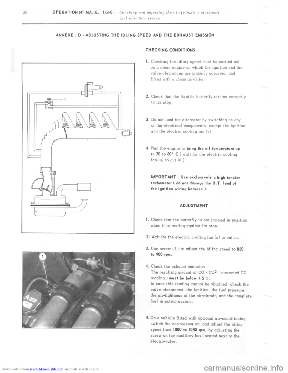
/,,,.I i,,jrr/io,, S~S,W1, ANNEXE : D - ADJUSTING THE IDLING SPEED AND THE EXHAUST EMISSION
CHECKING CONDITIONS
1.
Checking the idling speed must be carried out
on a clean engine on which the ignition and the
valve clearances are properly adjusted and
fitted with a clean air-filter.
2. Check that the throttle butterfly returns correctly
to its stop.
3. Do not load the alternator by switching an any
of the electrical components, except the iqnition
and the electric cooling fan (s) 4.
Run the engine to bring the oil temperature up
to 70 +o 80’ C ( wait for the electric cooling
fan is) to cut in ). IMPORTANT : Use exclusively (I high tension
tachometer ( do not damage the H.T. lead of
the ignition wiring harness ).
ADJUSTMENT
1. Check that the butterfly is not jammed in position
when it is resting against its stop.
2. Wait for the electric cooling fan (s) to cut in.
3. Use screw ( 1 ) to adjust the idling speed to 850
to 900 rpm.
4. Check the exhaust emission :
The resulting amount of CO - CO2 ( corrected CO
reading 1 must be beI& 4.5 %.
In case this reading cannot be obtained, check the
valve clearances, the ignition, the fuel pressure,
the air-tightness of the aircircuit, and the complete
fuel injection system.
5. On (I vehicle fitted with optional oirtonditioning
switch the compressor on, and adjust the idling
speed from 1000 to 1050
rpm, by adjusting the
screw on the auxiliary box located next to the
electro-vol”e.
Page 165 of 394

Downloaded from www.Manualslib.com manuals search engine OPERATION No MA. 220-O : (.hrrkinfi Ih e oil pr~ssrrrc m the rehicle Op. MA. 220.0 1
CHECKING THE OIL PRESSURE ON THE VEHICLE
79-T 1. Remove spare
wheel.
2. Check oil level if necessary.
4. Preparing pressure checking apparatus
Connect pressure gauge 2279-T ( ,wdun/r~l
imn 0 /o IO hnrs 1 to union 6004-T.
Tiqhten union screw ( 3 )
6. Start engine With oil temperature at 100’ C pressure should
be :
a+ 2000 rpm 3 bars mini43.5 psi ) o+ 4000 rpm 4 to 5 bars (58 to 72.5psi)
7. Rrmave union 6004-T and pressure qouqe. Tightening torque : 30 to 35 m \ ( 3 to 3.5 m.kg)
( 21 l/2 to 25 l/2 ft.lb )
Connect supply lead
Replace spare wheel
NOTE This operation con also be carried out
with the aid of CI MULLER kit,reference 451.