1984 CHEVROLET CAVALIER lights
[x] Cancel search: lightsPage 6 of 105
Downloaded from www.Manualslib.com manuals search engine SECTION 1
BEFORE DRIVING YOUR CAVALIER
TRANSAXLE
While reading this manual, you will nole many references 10 Ihe "transaxle." The transaxle is a transmission and differential (axle) combined in a singl ,e unit.
To avoid confusion, the word
"transaxle" will be used throughout this manual 10 refer to bolh Ihe transmission and differenlial funclions.
DRIVER DAILY CHECKUST
Be sure you know how to use your vehicle and its equipment before operating it
Before Entering the Vehicle
1. See that windows, mirrors and lights are clean and unobstructed.
2. If any lire does not look normal, check it with a pressure gage.
3. Look for fluid leaks .
4. Be sure everything is properly stowed.
5. Check the area behind the vehicle if you are about to back up.
__ Before Driving Off
1. Lock all doors.
2. Adjust the seat and any movable head restraint
3. Adjust inside and outside mirrors.
4. DO NOT allow anyone to ride where there is no seat belt ; and ALWAYS properly fasten the seat belt.
5. Check that all the warning lights work as the key is turned to "Run" or "Start"
6. Check all gages (including the fuel gage).
7 . Release the parking brake (and make sure the
"BRAKE " light turns .off).
See related topics in this manual
or the Maintenance Schedule folder H problems are found.
STOWING THINGS IN (OR ON) THE VEHICLE
CAUTION: Put luggage or cargo In the trunk, or rea' area if postible. Cargo weight,
whether In the trunk or rear area, should be located as far forward as possible. Cargo weight on the roof Shoukt be positioned .s evenly as possible. Secure all i1ems in place to help keep them -from being thrown about and injuring people during a cot"-ion or sudden maneuver. Do not pile luggage or cargo higher than the seetbaCks. Do not place anything on the filler panel, or any cargo cover between the rear seat~.ck and window.
GUARD AGAINST THEFT
Your new Cava~er has many features to help prevent then of the vehicle, its
equipment, and contents. But these anti-then features
depend upon you to work.
t -1
Page 25 of 105
Downloaded from www.Manualslib.com manuals search engine • Lane Change Signal -In some turns, such as changing lanes, the steering wheel tS not turned far enough to cancel the turn signal. For convenience, you can flash the turn signal by moving the lever part way (to the first stop)
and holding it there. The lever will return to horizontal when you release it.
A green light on the instrument panel is designed to flash to tell you that the
front
and rear turn signal lights are working. If the light stays on, but does not flash, check for burned-out turn signal bulbs. If the green light does not come
on when
you move the lever, check the fuse and indicator bulb.
However, if you ordered a trailertowing·optiOil.·in which extra wiring was added to attach the trailer lighting, a different type of flasher was installed. In this
case, the green light will continue to flash even if a turn signal bulb burns out.
Therefore, you must regularly look at the front
and rear turn signal lights to be
sure they are working.
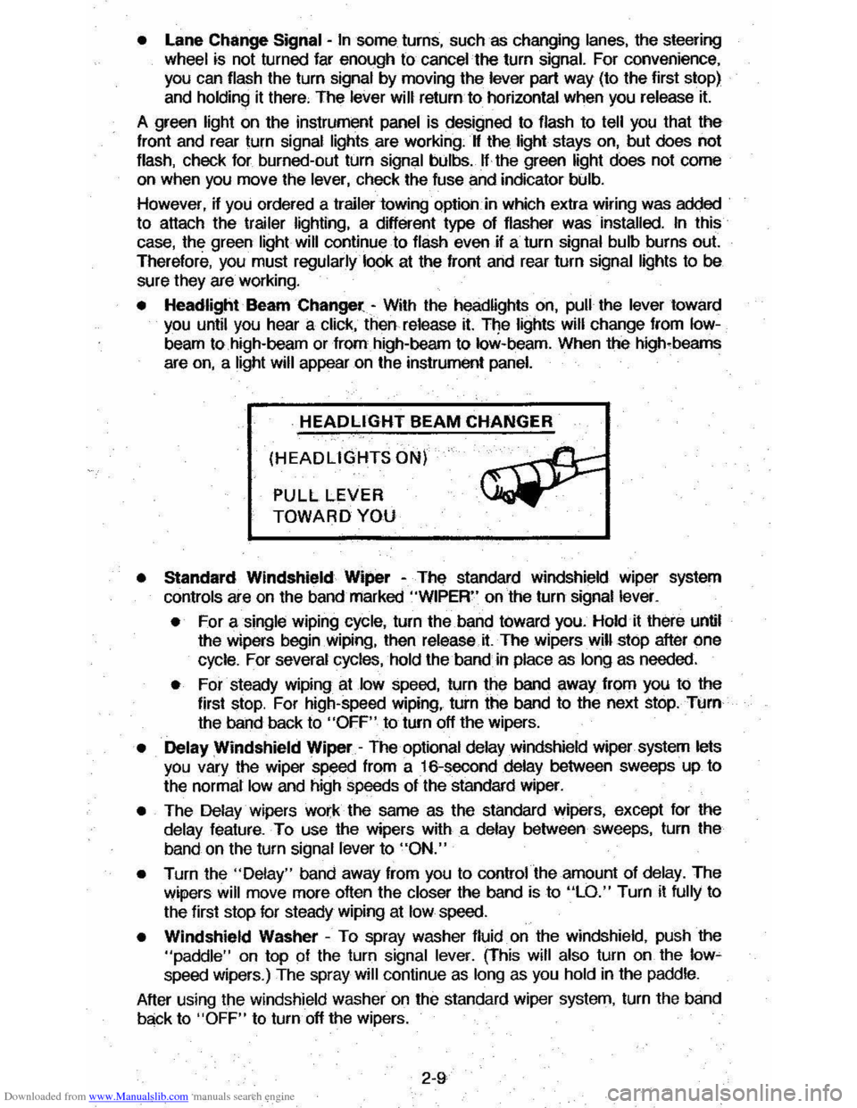
• Headlight Beam Changer -With the headlights on, pull the lever toward you until you hear a click, then release it. The lights will change from Iow
beam to high-beam or from high-beam to low-beam. When the high-beams
are
on, a light will appear on the instrument panel.
HEADLIGHT BEAM CHANGER
(HEADLIGHTS ON)
PULL LEVER
TOWARD YOU
• Standard Windshield Wiper -The standard Windshield wiper system
con
ols are on the band marked "WIPER" on the turn signal lever.
• For a single wiping cycle, turn the band toward you. Hold it there until
the wipers begin
Wiping, then release.it. The wipers will stop after one
cycle. For several cycles, hold the band in place as long as needed.
• For steady wiping at low speed, turn the band away from you to the
first stop. For high-speed wiping, turn the band to the next stop. Turn
the band back to
"OFF" to turn off the wipers.
• Delay Windshield Wiper -The optional delay windshield wiper system lets you vary the wiper speed from a 16-second delay between sweeps up to
the normal
low and high speeds of the standard wiper.
• The Delay wipers work the same as the standard wipers, except for the
delay feature. To use the wipers with a delay between sweeps, turn the
band on the turn signal lever to
"ON."
• Turn the "Delay" band away from you to control the amount of delay. The
wipers will move more often the closer the band is to "LO." Turn it fully to
the first stop for steady wiping at
low speed.
• Windshield Washer -To spray washer fluid on the windshield, pUSh the "paddle" on top of the turn signal lever. (This will also turn on the low~ speed wipers.) The spray will continue as long as you hold in the paddle.
After using the windshield washer
on the standard wiper system, turn the band
back to "OFF" to turn off the wipers.
2-9
Page 36 of 105
Downloaded from www.Manualslib.com manuals search engine DISC BRAKE WEAR INDICATORS
Front disc brake pads have buin-in wear indicators which should make a high
pitched squealing or cricket-like warning sound when the brake pads are worn
to where new pads are needed . The sound will oome and
go. or be heard all the time when the vehicle is moving and when the brake pedal is pushed down
firmly. Expensive rotor damage can result if pads are not replaced when needed. See also the brake checks listed in the Maintenance Schedule folder.
INSTRUMENT PANEL AND CONTROLS
INSTRUMENTS
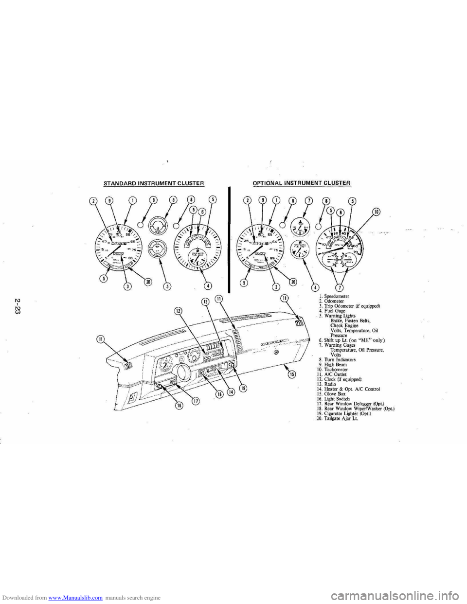
The instruments . gages and indicator lights conveniently grouped in the
instrument
cluster are designed to tell you at a glance many important things
about the performance of your Vehicle . The following information will enable
you to more quickly understand and properly interpret these instruments.
Speedometer
The speedometer hand indicates vehicle speed in miles per hour and
kilometers per hour.
Odometer
The group of figures in' the speedometer lower center section indicates the
accumulated mileage or kilometers .
Tamper-Resistant Odometer
Federal law prohibits tampering with vehicle odometers to aner accumulated
mileage. For your protection the odometer of this vehicle is designed with
tamper-resistant features to indicate
tarnpetiog . " silver lines appear vertically
between odometer numerals. it Is likely that the odometer has been turned
back or reversed . The mileage shown may not be actual. .
Whenever a new odometer is installed and cannot be set to the same mileage registered on the prior odometer . the law requires the owner to install a label
on thedriver's door frame to show the previous odometer reading and the date
of rep~. The · replacement odometer must then be set to zero . To
determine the actual vehicle
mileage. add the mileage shown on the label to . the current odometer reading. If the replacement odometer can be set up to
the same mileage as the prior odometer. no door frame
label is needed.
Trip Odometer
A trip odometer is used to record mileage on trips or during extended driving.
The trip odometer can be reset to zero by pushing the knob located in the
speedometer /odometer face until all zeros appear.
Fuei Gage
The fuel gage will register the APPAOXIMA TE fuel level in the tank. when the
ignition is in the RUN position .
When the gage registers EMPTY. some
fuel is still available as a reserve .
When the gage registers FULL. some additional fuel can still be added to the
tank . The fOllowing oonditions may be oonsidered normal:
•
Fuel station pump may shut off before fuel gage indicates FULL .
2-20
Page 39 of 105
Downloaded from www.Manualslib.com manuals search engine '" ,
t:l
STANDARD INSTRUMENT CLUSTER
IJ
12
OPTIONAL INSTRUMENT CLUSTER
~~~~-:'----,~~:
l'l
1l
10
L Speedometer 2. Odometer 3. Trip ()jometer lif equipped) 4. Fuel Gage 5. Warning Lights Brake, Fasten Belts, Check. Engine Volts, Temperature, Oil Pressure 6. Shift up Lt. (on "ME"only) 7. Warning Gages Temperature, on Pressure, Volts 8. Turn Indicators 9. High Beam 10. Tachomet er 11. A/C Outlet 12. Clock. (if equipped) 13. Radio 14. Heater & Opt. Ale Control 15. Glove Box 16. Lig ht Switch 17. Rear Window Defogger (Opt.) 18. Rear Window WiperlWasher (Opt.) 19. Cigare tt e Lighter (Opt.) 20, Tailgat e Ajar Lt.
Page 40 of 105
Downloaded from www.Manualslib.com manuals search engine Engine Coolant Temperature Gage
This optional gage is located in the instrument cluster. If the gage shows that
an overheat condition exists-as indicated by pointer moving beyond the
center of the band immediate action by the driver is required. If an overheat
condition is shown, see "Engine
Cooling System Overheating" in "In Case of
Emergency,"
Section 3 of this manual. The coolant temperature indication will VaIY with air temperature and operating conditions. The ignition must be in
"Run" for accurate readings. Prolonged driving or idling in very hot weather
may cause the pointer to move beyond the center of the gage. Make a practice
of scanning this and other gages
while driving, especially in hot weather and!
or when the
vehicle is under load.
CAUTION: II the Engine Coolant Temperature Gage shows an overheat condition or you have other reason to suspect the engine may be overheating, continued operation of the engine EVEN FOR A SHORT TIME may result in a fire and the risk of personal injury and/or severe vehicle damage. Take immediate action as outlined under "Engine Cooling System Overheating" in "In Case of Emergency," Section 3.
Oil Pressure Gage
The oil pressure gage indicates the pressure at which oil is being delivered to
the vaIiOUS paIls of the engine requiring lubrication. Pressures registered by
the gage may
vBIY according to outside air temperatures or weight of oil being
used. Oil pressure of a cold engine being operated at a given speed will be
somewhat higher than when the engine is at normal operating temperature at
the
SaIne speed. Prolonged high speed operation on a hot day at the given
speed will
resuH in somewhatlower oil pressure readings. Readings of 205 to
275 kPa
(30 to 40 psi) may be considered normal during moderate road
speeds of 35 to 40 mph (55 to 60 km!h) with the engine at proper operating
temperature. Gage readings which are consistently high
or low under these conditions may indicate lubrication system and/ or engine malfunction.
Light Switch
The three· position light switch controls the headlights, taillights, paIking lights,
sidemaIker lights,
instrument lights and dome lights.
Instrument light intensity can be varied by turning knob clockwise or
counterclockwise. Full counterclockwise position turns on interior light.
The headlight circuit is protected by a circuit breaker in the
light switch. An overload on the breaker will cause the lights to "flicker" on and off. If this
condition
develops, have your headlight wiring checked immediately. The
headlight beaIn changer is located in the Turn Signal Lever; for operation see
Section 2 under heading "Turn Signal and Muiji-Function Lever."·
Headlight High Beam Indicator Light
The headlights of your vehicle have. high and low beams to provide you with
proper nighttime visibility for most driving conditions. The
"low" beams are
used during most city driving. The
"high" beams are especially useful when
driving on daIk roads since they provide long range illumination. The headlight
beam indicator light (located on the speedometer face) will be ON whenever
the high beams or "brights" are in use. The turn
signal lever controls the
headlight beaIns and is described in "Steering Column Controls."
2-24
Page 41 of 105
Downloaded from www.Manualslib.com manuals search engine Headlight "ON" Warning Buzzer/Chime
The optional headlight reminder buzzer/chime provides an audible warning that the main light switch is in one 01 the "on" positions , either parking lights
or headlights.
The reminder buzzer/chime is activated only when the ignition switch is turned to "OFF," "LOCK" or "ACCESSORY" position and the lights are on.
When the parking lights
or headlights are to be operated with the key in the
OFF position, the reminder buzzer/chime can be shut off by turning the light
switch knob until the instrument cluster lights are not on,
CIgarette Ughter (Optional)
The cigarette lighter is located on the instrument pane! face. To operate, push
~ in. When ~ becomes heated, ~ automatically pops out ready for use. Avoid
holding the lighter in by hand while ~ is heating as damage to the heating
element may result.
Ashtray
The ashtray may be simply pulled out for cleaning:
• Open ashtray.
• Pull ashtray up and remove for cleaning .
•
Push ashtray back into bracket.
VENTILATION SYSTEM
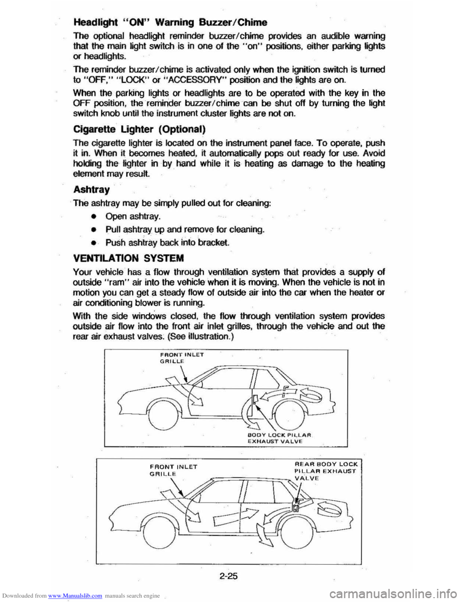
Your vehicle has a flow through ventilation system that provides a supply of outside "ram" air into the vehicle ' when it is moving . When the vehicle is not in
motion you can get a steady flow of outside air into the car when the heater or
air conditioning blower is running.
With the side
windOws closed, the flow lIYough ventilation system provides
outside air flow into the front air inlet grilles, through the vehicle and out the
rear air exhaust valves. (See illustration .)
FRONT INLET
2-25
REAR BODY LOCK PILLAR EXHAUST
Page 59 of 105
Downloaded from www.Manualslib.com manuals search engine •
~-
SECTION 3
IN CASE OF EMERGENCY
. FOUR·WAY HAZARD WARNING FLASHER
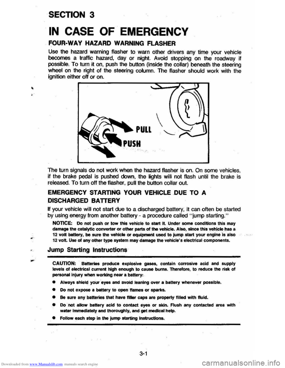
Use the hazard warning flasher to warn other drivers any time your vehicle becomes a traffic hazard. day or night. Avoid stopping on the roadway if possible, To turn it on. push the button (inside the collar) beneath the steering
wheelan the right of the steering column. The flasher should work with the
ignition either off or on .
The turn
signals do not work when the hazard flasher is on. On some vehicles. if the brake pedal is pushed down. the lights will not flash until the brake is
released. To turn off the flasher. pull the button collar out.
EMERGENCY STARTING YOUR VEHICI.E .DUE TO A
DISCHARGED BATTERY
H your vehicle will not start rue to a discharged battery. it can often be started
by using energy from another battery -a procedure called "jump starting."
NOnCE: Do not push or tow thl' vehicle to start It. Under some conditions this may damage the catalytlc ·converter or other parts of the vehicle. Alao, 'since this vehicle ,has a 12 volt bettery, be sure the vehlc .. or equiprnetlt used to jump start your engine Is also 12 volt. Use of any other type syltem mey damage the vehicle', electrical components.
Jump Starting Instructions
CAUTION: Battet1H productl .~ gases, contain corrosive acid and supply ~ls of electrical current hlgh enough &0 cause bums. Therefore, to reduce the risk of peraoMIlnjury when working near 8 banery:
• Always shield your ayes and avOid leaning over a MtttIry whenever possible.
• Do not expose a battery to open,'ftames or spark&.
• Be sure any batter. that have fll .... caps are properly filled with fluid.
• Do not _aDow battery acid to contact eyes or skin. Flush any contacted area with w8ter Immediately and thOrOughly. Mel get mecIcaI hMp.
• FoUow each -step in the jump at8rting Jnstructiona.
3-1
Page 60 of 105
Downloaded from www.Manualslib.com manuals search engine 1. Position the vehicle with the good (charged) battery so that the booster Qumper) cables will reach but never let the vehicles touch. Also, be sure
booster cables to be used do not have loose or missing insulation.
2. tn both vehicles :
• Turn off ignition and all lights and accessories except the hazard
flasher or any lights needed for lhe work area.
• Apply the parking brake firmly, and shift the automatic transaxle or transmission to Park (or manual transaxle or transmission to neutral).
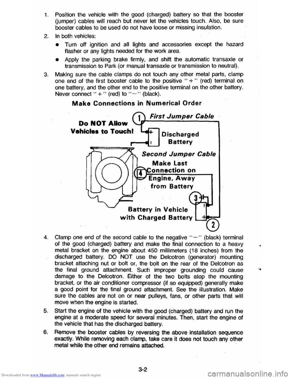
3. Making sure the cable clamps do not touch any other metal parts, clamp
one end of the first booster cable to the positive " +" (red) terminal on
one battery, and the other end to the positive terminal on the other battery .
Never connect"
+ " (red) to "- " (black).
Make Connections in Numerical Order
First Jump.r C.bl.
Do NOT Allow
Vehicle. to Touchl Discharged
Battery
S.cond Jump.r C.bl.
Make Last
onnectlon on
Engine,
Away
from Battery
Battery in Vehicle
with Charged Battery L-'= ___
o
4. Clamp one end of the second cable to the negative" -" (black) terminal
of the
good (charged) battery and make the final connection to a heavy metal bracket on the engine about 450 millimeters (18 inches) from the
discharged battery.
DO NOT use the Delcotron (generator) mounting
bracket attaching nut or bolt or, the bolt on the rear of the Delcotron as
the final ground attachment. Such improper grounding could cause
damage to the Delcotron . Either of the two bolts atop the mounting
bracket ,
or the air conditioner compressor (if so equipped) generally make a good point for the final ground attachment. See the illustration. Make
sure
the cables are not on or near pulleys , fans , or other parts that will move when the engine is started.
5. Start the engine of the vehicle with the good (charged) battery and run the
engine at a moderate speed for several minutes. Then, start the engine of
the vehicle that has the discharged battery.
6. Remove the booster cables by. raversing the above installation sequence
exactly. While removing each clamp, take care it does not touch any other metal while the other end remains attached. .
3-2
•