1984 CHEVROLET CAVALIER fuel
[x] Cancel search: fuelPage 34 of 105
Downloaded from www.Manualslib.com manuals search engine When_ going up or down hills. it ~ ~ tor the vehk:1e to toM 011 to gain apHCI (.,.rticu"Y when towing I trailer), even though the Cruise Control is enpgecL • this happens while going up hin, merely depress the accelerator pedal to maintain the speed desired. If going down a hili steep enough to cau .. thl vehie'" to gain speed, depress the brake pedal •• which will both dl .. ngage the Cruise Control and help .lOw the vehicle. In addition, when going down a steep or lang grade . the transaxle shoUld be shifted into I lower gear to help control vehicte speed •• see "Descending A Grade " in "Starting and Operating," Section 2.
HORN
The horn on your vehicle is actuated by firmly pressing on the ped in the
center of the steering
wheel.
HAZARD WARNING FLASHER
The hazard warning flasher is covered in "In Case of Emergency," Section 3.
FLOOR CONTROLS
BRAKING SYSTEM
The regular braking system is designed for braking performance under a wide
range of driving cond~ions even when the vehicle is loaded to ~ lull rated
vehicle toad capacity .
CAUTION: Driving through water deep enough to wet brake components may cau .. the brakea nat to work .. welL -M a reaul, the vehIde wi. not aIow down .. the usu.I _, ond M may pull 10 "'" right Of ..... _ 0"'-""'11 to "'" _ tor _ .-.os,
-'1 "'" ...... lightly 10 check __ .... "-'"
Brake Warning lJg/rt
The brake system warning light is covered in the '.' lnstrumentPanel" section.
Vacuum Power Brakes
• the engine stops, do not pump the brakes. The system is designed to stop the vehicle with reserve power assist n the brake pedal is held dOwn. This
reserve is
greatly reduced each time you apply and release the brakes. II,
when you turn the atMring wheel during braking, the vehic:1e does not turn, don't push as hard on the brake pedal •.
Without power assist the vehicle can still be stopped by pushing much harder
on the brake
pedal. however. the stopping distance may be longer.
Brakes (Except ,Parking Brake)
H the brake pedaJ goes down farther than normal, ~ may be due to a lack of
adjustment of any rear drum
brakes. To find. out if this is the case. drive
backward and forward a few times. applying the brakes firmly when going in
each direction.
See your dealer n pedal height dOes not retum to normal, or there is a rapid
increase in pedal travel whether or not your vehicle has rear drum brakes. This
could be a sign of brake trOUble.
NOTICE: "FtidInsI the brake" by resting yow i0oi on thl brau pedal when you do not Intend 'to brake CIIf1 overhMI: the brIkM and ...... out the brake InInga and p..ts faster. , ThI. mIIy alSo dllNlge the brakes Mtd will wasta fuel.
2-18
Page 36 of 105
Downloaded from www.Manualslib.com manuals search engine DISC BRAKE WEAR INDICATORS
Front disc brake pads have buin-in wear indicators which should make a high
pitched squealing or cricket-like warning sound when the brake pads are worn
to where new pads are needed . The sound will oome and
go. or be heard all the time when the vehicle is moving and when the brake pedal is pushed down
firmly. Expensive rotor damage can result if pads are not replaced when needed. See also the brake checks listed in the Maintenance Schedule folder.
INSTRUMENT PANEL AND CONTROLS
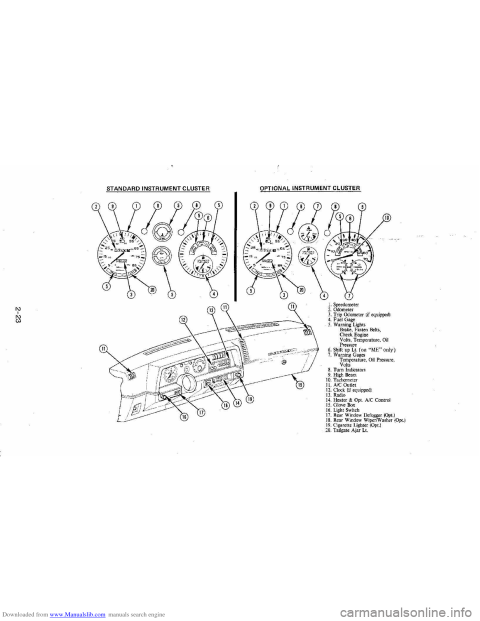
INSTRUMENTS
The instruments . gages and indicator lights conveniently grouped in the
instrument
cluster are designed to tell you at a glance many important things
about the performance of your Vehicle . The following information will enable
you to more quickly understand and properly interpret these instruments.
Speedometer
The speedometer hand indicates vehicle speed in miles per hour and
kilometers per hour.
Odometer
The group of figures in' the speedometer lower center section indicates the
accumulated mileage or kilometers .
Tamper-Resistant Odometer
Federal law prohibits tampering with vehicle odometers to aner accumulated
mileage. For your protection the odometer of this vehicle is designed with
tamper-resistant features to indicate
tarnpetiog . " silver lines appear vertically
between odometer numerals. it Is likely that the odometer has been turned
back or reversed . The mileage shown may not be actual. .
Whenever a new odometer is installed and cannot be set to the same mileage registered on the prior odometer . the law requires the owner to install a label
on thedriver's door frame to show the previous odometer reading and the date
of rep~. The · replacement odometer must then be set to zero . To
determine the actual vehicle
mileage. add the mileage shown on the label to . the current odometer reading. If the replacement odometer can be set up to
the same mileage as the prior odometer. no door frame
label is needed.
Trip Odometer
A trip odometer is used to record mileage on trips or during extended driving.
The trip odometer can be reset to zero by pushing the knob located in the
speedometer /odometer face until all zeros appear.
Fuei Gage
The fuel gage will register the APPAOXIMA TE fuel level in the tank. when the
ignition is in the RUN position .
When the gage registers EMPTY. some
fuel is still available as a reserve .
When the gage registers FULL. some additional fuel can still be added to the
tank . The fOllowing oonditions may be oonsidered normal:
•
Fuel station pump may shut off before fuel gage indicates FULL .
2-20
Page 37 of 105
Downloaded from www.Manualslib.com manuals search engine • Amount of fuel required for fill-up may not exactly correspond to gage.
• Needle may not move away from FULL until some time after fill-up.
• Needle may move during turns; stops and accelerations.
When the ignition switch is turned to the OFF position, the needle will not
necessarily return
all the way to the EMPTY mark.
Oil Pressure Light
When the ignition is turned to "Run," the "Oil" warning light appears until the
engine is started. Thereafter, the light should be off unless there is insufficient
oil pressure or engine idle speed is below normal. If the light should come on
at any time while driving (other than momentarily at idle speed or after a
sudden stop), stop immediately and investigate the cause of
low oil pressure.
This could possibly be caused by low oil level in the crankcase. Engine
operation with low oil pressure will 9ause damage to the engine.
Engine Coolant Temperature Light
This light is located in the instrument cluster and is designed to come on to warn the driver that the engine coolant has overheated and immediate
action is required to correct the condition. As a check that the bulb and its
circuit are working, the light will come on during engine starting; if it does not,
have it repaired
promptly. If the light comes on at any other time, see "Engine
Cooling System Overheating" in "In Case of Emergency," Section 3 of this manual.
CAUTION: It the Engine Coolant Temperature Light shows an overheat condition or you have other reason to suspect the engine may be overheating, continued operation of the engine EVEN FOR A SHORT TIME may result in a fire and the risk of personal injury and/or severe vehicle damage. Take immediate action as outlined under "Engine Cooling System Overheating" in "In Case of Emergency," Section 3.
Generator Indicator Light
The VOLT light is designed to come on when the ignition key is in the "RUN" position, but before the engine is started. After the engine starts, the light
should go out and remain out. If the light remains· on when engine is running,
have your authorized
dealer locate and correct the trouble as soon as possible.
Shift Indicator Light
The Shift Indicator Light is covered in the "Manual Transaxle" information in
this section.
"Check Engine" Light
Most gasoline engine vehicles sold in the Unijed States (and some vehicles
sold
in Canada) have the Computer Command Control system.
Vehicles with the Computer Command Control system include a "CHECK
ENGINE" light
on the instrument panel designed to indicate the need for
system service. It will come on during engine starting to let you know the bulb
is working. (The light will stay on a short time after the engine starts.)
2-21
Page 38 of 105
Downloaded from www.Manualslib.com manuals search engine Have the system repaired n the "CHECK ENGINE" light does not come on during engine starting. If the light comes on, either intermittently or
continuously while driving, service to the Computer Command Control system
is required. AHhough in most cases the vehicle is drivable, and does not
require towing, see your authorized
dealer as soon as possible for service of
the system.
Continued driving without having the Computer
Command Control system serviced could cause damage to the emission control system. It could also affect fuel economy and drivability.
See also "Computer Command Control system" in Section 5 of this manual.
Brake System Warning Light
The regular braking system is a dual system designed so that one part will
provide some braking if there is a
loss of hydraulic pressure in the other part of
the system. The system has a
"BRAKE" warning light located in the
instrument panel. The "BRAKE" light is designed to come on briefly during
engine starting so you can check that the bulb is okay. To serve as a reminder,
the
light should stay on when the parking brake is not fully released and the
ignition is
on. Have the system repaired if the light does not come on when it should. This warning light does not do away with the need for brake inspection
and maintenaflce. The brakelluid level must be checked regularly. See your
Maintenance Schedule folder for other brake checks.
I! the light remains on aller engine start up or comes on during operation of the vehicle, it may mean that there is something wrong with part of the brake
system.
What
to do:
1. Check to see that the parking brake has been released. I! it has been:
2. Pull off the road and stop carefully. Remember that:
• Stopping distances may be longer.
•
You may have to push harder on the pedal.
•
The pedal may go down farther than normal.
3. Tryout the brakes by starting and stopping on the road shoulder--then:
• I! you judge it to be safe, drive cautiously at a safe speed to the
nearest dealer for repair. Or,
• Have vehicle towed to the nearest dealer for repair.
Continued driving without getting necessary repairs
could be dangerous.
Tachometer
The optional tachometer indicates the speed of the engine in revolutions per
minute. The indicated number, times
100, gives the engine speed. Operating
the engine with the tachometer reading in the color-coded high-speed area
could lead to serious engine damage.
Voltmeter
When the engine is operating, the voltmeter indicates the electrical system
voltage. During minimum electrical load, the pointer will read to the right of the
center.
As the electrical load is increased, or in stop-and-go driving, the pointer
will rotate to the Ieli. A meter reading continuously in the left or right zone
indicates
an electrical system failure. Cause of the failure should be determined and corrected.
2-22
Page 39 of 105
Downloaded from www.Manualslib.com manuals search engine '" ,
t:l
STANDARD INSTRUMENT CLUSTER
IJ
12
OPTIONAL INSTRUMENT CLUSTER
~~~~-:'----,~~:
l'l
1l
10
L Speedometer 2. Odometer 3. Trip ()jometer lif equipped) 4. Fuel Gage 5. Warning Lights Brake, Fasten Belts, Check. Engine Volts, Temperature, Oil Pressure 6. Shift up Lt. (on "ME"only) 7. Warning Gages Temperature, on Pressure, Volts 8. Turn Indicators 9. High Beam 10. Tachomet er 11. A/C Outlet 12. Clock. (if equipped) 13. Radio 14. Heater & Opt. Ale Control 15. Glove Box 16. Lig ht Switch 17. Rear Window Defogger (Opt.) 18. Rear Window WiperlWasher (Opt.) 19. Cigare tt e Lighter (Opt.) 20, Tailgat e Ajar Lt.
Page 43 of 105
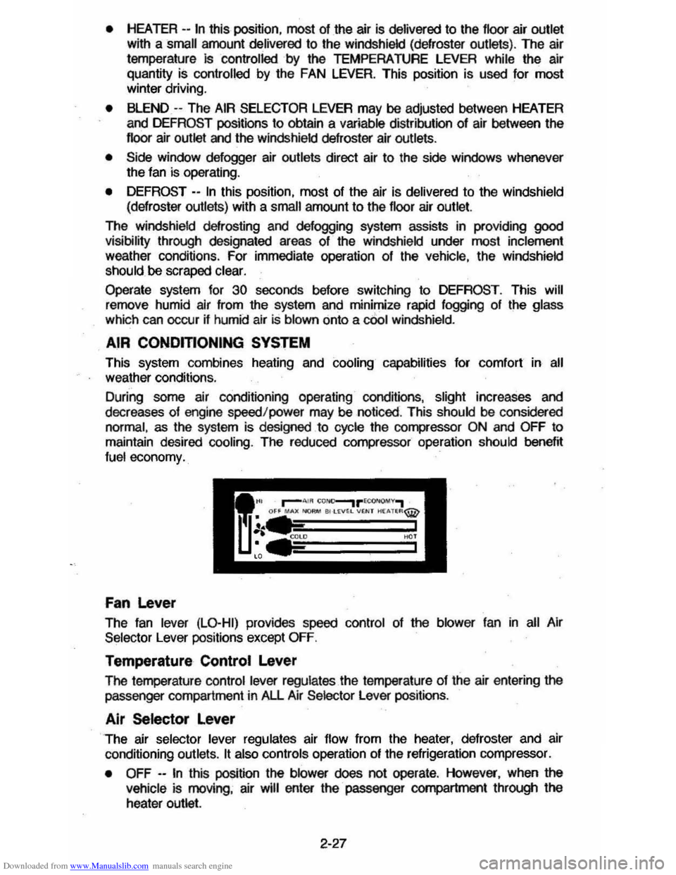
Downloaded from www.Manualslib.com manuals search engine • HEATER --In this position, most of the air is delivered to the floor air outlet
with a small amount delivered to the windshield (defroster outlets). The air
temperature
Is controlled by the TEMPERATURE LEVER while the air
quantity
is controlled by the FAN LEVER. This position is used for most winter driving.
• BLEND -- The AIR SELECTOR LEVER may be adjusted between HEATER
and DEFROST positions to obtain a variable distribution of air between the
floor air outlet and the windsh ield defroster air outlets.
• Side window defogger air outlets direct air to the side windows whenever
the fan is operating.
•
DEFROST - -In this poSition, most of the air is delivered to the windshield
(defroster outlets) with a small amount
to the floor air outlet.
The windshield defrosting and defogging system assists in providing
good visibility through designated areas of the windshield under most inclement
weather conditions . For immediate operation of the vehicle, the windshield
should be scraped clear.
Operate system for 30 seconds before switching to DEFROST . This will
remove humid air from the system
and minimize rapid fogging of the glass
which can occur if humid air Is blown onto a cOol windshield .
AIR CONOmONING SYSTEM
This system combines heating and cOOling capabilities for comfort in all weather conditions.
During some air conditioning operating conditions, slight increases and
decreases of engine speed/power may be noticed . This
should be considered
normal, as the system is designed to cycle the compressor
ON and OFF to
maintain desired cooling. The reduced compressor operation should
benef~ fuel economy.
Fan Lever
The fan lever (LO-HI) provides speed control of the blower fan in all Air
Selector Lever positions except
OFF.
Temperature Control Lever
The femperature control lever regulates the temperature of the air entering the passenger compartment in All Air Selector Lever positions .
Air Selector Lever
The air selector lever regulates air flow from the heater, defroster and air
conditioning outlets.
It also controls operation of the refrigeration compressor.
•
OFF --In this position the blower does not operate . However, when the
vehicle is moving, air will enter the· passenger compartment through the
heater outlet.
2-27
Page 65 of 105

Downloaded from www.Manualslib.com manuals search engine 3. Install wheel and tire assembly and install hub cap by pushing or hitting
into place (the wheel can be mounted with hub cap in place). The hub cap
must be oriented by engaging the bump on the side of the hub cap
retention tab with the cutout on the side of the wheel pilot hole.
Compact Spare
The compact spare tire is designed to save space in your stowage area, and
its lighter weight makes it easier to install if a flat tire occurs. The lighter weight also helps improve fuel economy. ~--~------~~
" you have a flat tire, follow the jacking Instructions in this section, while keepingihese points in mind:
• Check the tire inflaiionpressureas soon as practical after installing the
spare (we suggest you use a 'pocket-type high'pressure inflation gage) and
adjust the pressure to 415
kilopascals (60 pounds per square inch). The
tire pressure should be checked at least monthly and kept at 415 kPa (60
psi) while the tire is stored . Also at least monthly , ·qheck that the spare lire is stowed securely ; tighten it if ~ is not.
NOTICE: Bee ... this tire is smaller than the standard tire, vehicle ground clearance is reduced. Do not take your vehicle through an automatic car wash while ~ spare I. Installed; the vehicle may catch on the equipment, possibly resulting In property damag_.
• YOU can expect a tread life up to 3,000 miles (4 800 kilometers), dependiQg on road conditions and your driving habits. The tire was designed to let you
finish an extended trip (up to 3,000 miles/4 800 kilometers) and buy a replacement tire, -if needed, at a store of your choice. However, to conserve
tire tread ~fe, return the spare to the stowage area as' soon as it is
convenient to have your standard tire repaired or replaced.
• Because the compact spare was specnically designed for your vehicle , ~ should not be used on any other vehicle.
• The compact spare tire and wheel are designed for use with each other.
The compact spare tire should not be mounted on any other type of wheel, and the compact spare wheel should not have any other type of tire
mounted on it. Also, do not try to use wheel covers or trim rings on the
CQr1l>aCt spare whe el since they will not fit. If such use is attempted,
damage to tIlese items or other vehicle components may occur.
• Do not use tire chains with your :compact spare tire. Because of the smaller tire size, a tire chain will not fit properly. This could cause damage to the
vehicle and result in loss of the chain.
3-7
Page 71 of 105
Downloaded from www.Manualslib.com manuals search engine Cleaning White Sidewall Tires
Use GM White Sidewall Tire Cleaner or a tire cleaner which will not harm aluminum wheel trim. A stiff brush may be used with the cleaner.
CORROSION PROTECTION
'four vehicle has been designed and built to resist corrosion. Special materials and protective finishes were used on most parts of your vehicle when it was
built to help maintain good looks, strength and reliable operation. However,
some parts which normally are not visible (such as certain parts under the
vehicle and under the hood) are such that surface rust will not affect their reliability. So, corrosion protection is not needed or used on these parts.
Sheet Metal Damage
If your vehicle is damaged and requires sheet metal repair or replacement, make sure the body repair shop applies anti-corrosion material to the parts
repaired or replaced so that corrosion protection is restored. (Also see "Finish Damage" which follows.)
Foreign Material Deposits
Calcium chloride and other salts, ice melting agents, road oil and tar, tree sap, bird droppings, chemicals from industrial chimneys, and other foreign matter
may damage vehicle finishes if left on painted surfaces.
Prompt washing may not completely remove all of these deposits. Other cleaners may be needed. When using chemical cleaners, be sure they are safe
for use on painted surfaces.
Finish Damage
Any stone chips, fractures or deep scratches in the finish should be repaired
promptly. Bare metal will corrode quickly and may develop into a major repair
expense.
Minor chips and scratches can be repaired with touch-up materials available from your dealer or other service outlets. Larger areas of finish damage can be
corrected in your dealer's body and paint shop.
Underbody Maintenance
Corrosive materials used for ice and snow removal and dust control can collect on the underbody. If these materials are not removed, accelerated corrosion
(rust) can occur on underbody parts such as fuel lines, frame, floor pan, and
exhaust system even though they have been provided with corrosion
protection.
At
least every spring, flush these materials from the underbody with plain
water. Take care to clean any areas where mud and other debris can collect.
Sediment packed in closed areas of the frame should be loosened before being flushed. If desired, your authorized dealer can do this service for you.
4-5