1983 FIAT UNO clock
[x] Cancel search: clockPage 227 of 303

14B.54 Master cylinder/vacuum servo
located next to the coolant expansion tank
(1301 cc Turbo ie model)
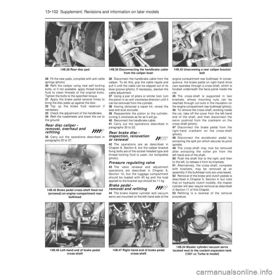
29Fit the new pads, complete with anti-rattle
springs (photo).
30Refit the caliper using new self-locking
bolts, or if not available, apply thread-locking
fluid to clean threads of the original bolts.
Tighten the bolts to the specified torque.
31Apply the brake pedal several times to
bring the disc pads up against the disc.
32Top up the brake fluid reservoir if
necessary.
33Check the adjustment of the handbrake.
34Refit the roadwheels and lower the car to
the ground.
Rear disc caliper -
removal, overhaul and
refitting
¢
35Carry out the operations described in
paragraphs 25 to 27.36Disconnect the handbrake cable from the
caliper. To do this, grip the cable nipple and
pull it until the cable can be slipped out of its
lever groove (photo). If necessary, slacken the
cable adjustment.
37Using a pair of pliers or similar tool, turn
the piston in an anti-clockwise direction until it
can be removed from the cylinder.
38Having obtained a repair kit, renew the
seal and dust excluder.
39Reassemble the piston to the cylinder,
turning it clockwise as far as it will go.
40Reconnect the handbrake cable.
41Carry out the operations described in
paragraphs 30 to 32.
Rear brake disc -
inspection, renovation
or renewal
ª
42The operations are as described in
Chapter 8, Section 6, but the caliper bracket
fixing bolts are of the socket-headed type and
thread-locking fluid is used, not lockplates
(photo).
Pressure regulating valve
43The valve renewal and adjustment
operations are described in Chapter 8,
Section 10, but the luggage compartment
should be loaded with 45 kg and the load
applied to the bracket eye should be 11 kg.
Brake pedal -
removal and refitting#
44The brake master cylinder and vacuum
servo are mounted on the left-hand side of theengine compartment rear bulkhead. In conse-
quence, the brake pedal on right-hand drive
cars operates through a cross-shaft, which is
located underneath the facia panel inside the
car.
45The cross-shaft is supported in two
brackets, whose mounting nuts can be
reached through cut-outs in the insulation on
the engine compartment rear bulkhead (photo).
46To remove the cross-shaft, working inside
the car, take off the cover from the left-hand
end of the shaft, and then disconnect the
servo pushrod from the crankarm on the
cross-shaft (photo).
47Disconnect the brake pedal from the
right-hand crankarm on the cross-shaft
(photo).
48Disconnect the accelerator pedal by
extracting the split pin which secures its pivot
spindle.
49The cross-shaft may now be removed
after extracting the cotter pin from the
left-hand end of the shaft.
50Push the shaft first to the right, and then
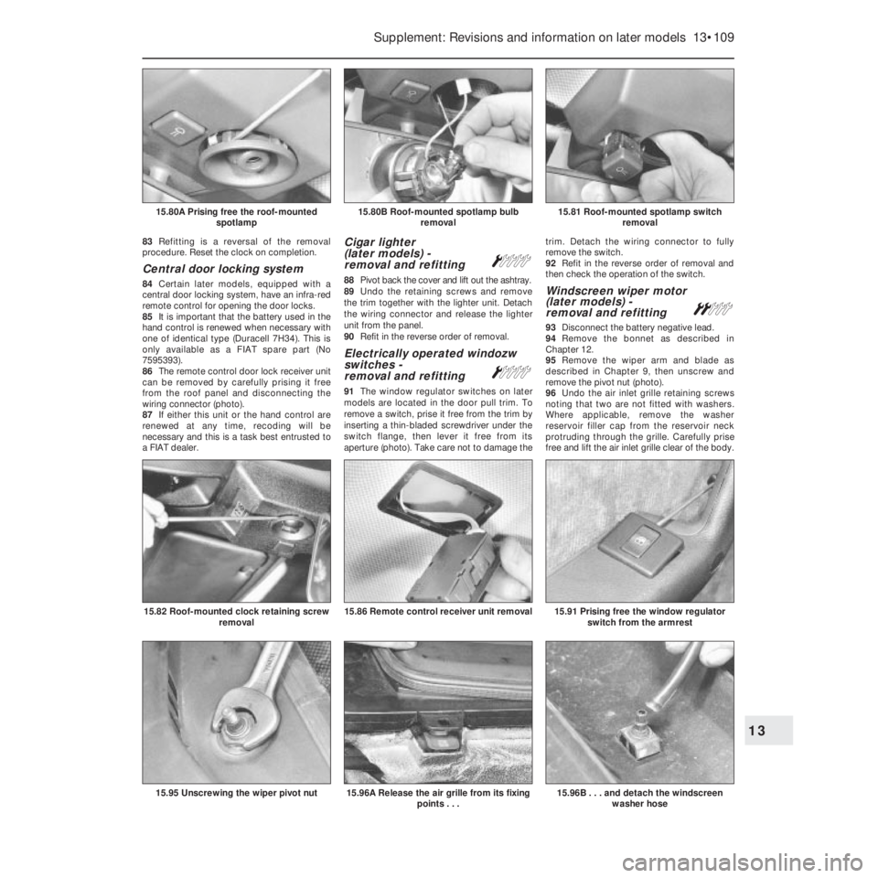
to the left, to release it from its brackets.
51Alternatively, the cross-shaft, complete
with brackets, may be removed as an
assembly if the bulkhead nuts are unscrewed.
52Removal of the brake and clutch pedals is
described in Chapter 5, Section 4, but note
that on hydraulic clutch models, the master
cylinder will also require removal as described
in Section 11 of this Chapter.
53Refitting is a reversal of the removal
procedure.
13•102 Supplement: Revisions and information on later models
14B.47 Right-hand end of brake pedal
cross-shaft14B.46 Left-hand end of brake pedal
cross-shaft
14B.45 Brake pedal cross-shaft fixed nut
(arrowed) on engine compartment rear
bulkhead
14B.42 Unscrewing a rear caliper bracket
bolt14B.36 Disconnecting the handbrake cable
from the caliper lever14B.29 Rear disc pad
Page 230 of 303

Starter motor brushes
(later models) - renewal#
25When renewing the starter motor brushes
on later models, the old brushes will need to
be crushed (in a vice or with a hammer) and
their leads then soldered to the new brushes.
Fuses - later models
26The fuse arrangement is slightly different
on later models, but the circuits protected are
still identified by a symbol. Refer to the
Specifications Section for full details. Note
also the terminal block with plastic cover,
which can be used to isolate the battery from
the electrical system by disconnecting the
leads from the terminals (photos).
Relays (Turbo ie models) -
general
27On Turbo ie models, the relays mounted
in the fuse block are as shown in Fig. 13.103.
Additional relays are located as follows:
Headlamp relay - on lead under main fuse
blockFuel injection system main control relay -
adjacent to airflow meter
Headlamps later models
28The headlamp units fitted on later models
differ according to model, but the bulb and
unit replacement details are generally the
same as described for previous models in
Chapter 9. Note that the rubber cover can
only be fitted with the tab to the top as shown
(photo).
Headlamp beam adjusters for
load compensation - later
models
29Some later models are fitted with
headlamp beam adjusters which allowtemporary resetting to be made (such as
when the car is fully loaded). Access to these
adjusters is made by lifting the bonnet (photo).
30Turn the adjusters anti-clockwise to lower
the beam to the normal level or clockwise to
raise the beam (when the car is unloaded).
Repeat the procedure on the opposite
headlamp unit an equal amount.
31Other later models have separate
horizontal and vertical beam adjusters,
positioned as shown (photos). A load
compensating lever is attached to the
adjusters to enable temporary resetting of the
headlamp beams, without changing the
normal adjustment. Turn the lever to the
appropriate side (right or left) to make the
adjustment as required. The normal setting
Supplement: Revisions and information on later models 13•105
15.26B Battery lead terminal block on the
1301 cc Turbo ie model15.23B Starter motor and wiring
connections on the 1372 cc ie engine
15.31B Headlamp vertical beam alignment
adjuster screw on a 1372 cc ie model. Note
the load compensator lever which is set in
the “O” (normal load) setting position15.31A Headlamp horizontal beam
alignment adjuster screw on a 1372 cc ie
model
15.29 Headlamp beam adjuster on the
999 cc Turbo ie model15.28 Headlamp unit fitted to the 1372 cc ie
model
15.26A Fuse block on the 1301 cc Turbo ie
model
13
Fig. 13.103 Auxiliary fuses and relays on
1301 cc Turbo ie models (Sec 15)
1 Horn relay
2 Heated rear screen relay
3 Foglamps relay
4 Radiator fan relay
5 Electric windows relay
6 Foglamps fuse
7 Radiator fan second speed fuse
8 Fuel injector fan fuse
9 Electric windows fuse
10 Electric fuel pump fuse
Page 233 of 303

Auxiliary control panel
(later models) -
removal and refitting
Á
61Disconnect the battery negative lead.
62Insert the flat of a screwdriver under the
trim piece at the end of the auxiliary panel as
shown and prise it free. Repeat the procedure
and remove the trim piece at the other end of
the panel (photo).
63Undo the retaining screws, withdraw the
panel from the facia. Disconnect the wiring
connectors from the panel switches to
remove the panel completely (photo).
64A switch bulb can be renewed by
untwisting the holder and removing the holder
and bulb.
65A switch unit can be removed from the
panel by unscrewing the four retaining screws.66Refitting is a reversal of the removal
procedure. Ensure that the wiring connections
are securely made and check for satisfactory
operation of the switches on completion.
Heater control panel
(later models) -
removal and refitting
Á
67Disconnect the battery negative lead.
68Pull free the heater/fresh air and blower
control knobs (photo).
69Undo the two retaining screws and
withdraw the control panel from the facia
(photos). Detach the wiring connectors from the
panel illumination lights and remove the panel.
70Refitting is a reversal of the removal
procedure. Ensure that the wiring connections
are securely made and on completion check
that the operation of the controls is satisfactory.
Trip master Á
71This electronic instrument is fitted into the
check panel of 1100SL and 1300SL models
from 1986.
72The device provides information on fuel
consumption, range, speed and elapsed time.
73With the ignition key turned to MAR,
figures are displayed in respect of the last
journey - average fuel consumption, average
speed and elapsed time (up to switching off
the ignition).
74As soon as the engine is started, the
instrument processes the current values to
include fuel consumption, range and the
actual time. 75Fuel consumption is only displayed when
the road speed exceeds 8.0 km/h (5.0 mph).
76The fuel range is only displayed after a
road speed of between 25.0 and 70.0 km/h
(15.0 to 44.0 mph) has been maintained for at
least 90 seconds or at higher speeds for
22 seconds.
77A reset button is provided, also a display
change button (from instant to average or
total values). Should the instrument reading
exceed 99 hours, 59 minutes or 1000 km
(622 miles) depressing the display change
button will display all zeros. Depress button E
to resume normal function.
78Refer to the end of the manual for a wiring
diagram of the check panel, incorporating the
trip master.
Interior roof mounted spotlamp,
switch and/or clock -
removal and refitting
Á
79Disconnect the battery negative lead.
80Prise free the lamp unit from its aperture
in the roof panel using a thin-bladed
screwdriver. The lamp bulb can be inspected
by untwisting the holder and withdrawing it
from the rear of the unit (photos). Extract the
bulb from the holder if it requires renewal.
81To remove the lamp switch from the
panel, reach through the lamp aperture and
press it free from the roof panel (photo).
Detach the wiring connectors.
82To remove the clock, reach through the
lamp aperture and undo the retaining screws
(photo). Withdraw the clock and detach the
wiring connectors.
13•108 Supplement: Revisions and information on later models
15.69B . . . and withdraw the heater control
panel15.69A . . . undo the retaining screws
(arrowed)15.68 Remove the control knobs . . .
15.63 . . . and withdraw the auxiliary
control panel
15.62 Prise free the trim covers for access
to retaining screws . . .15.59B . . . and disconnect the
speedometer cable15.59A . . . withdraw the instrument
panel . . .
Page 234 of 303

83Refitting is a reversal of the removal
procedure. Reset the clock on completion.
Central door locking system
84Certain later models, equipped with a
central door locking system, have an infra-red
remote control for opening the door locks.
85It is important that the battery used in the
hand control is renewed when necessary with
one of identical type (Duracell 7H34). This is
only available as a FIAT spare part (No
7595393).
86The remote control door lock receiver unit
can be removed by carefully prising it free
from the roof panel and disconnecting the
wiring connector (photo).
87If either this unit or the hand control are
renewed at any time, recoding will be
necessary and this is a task best entrusted to
a FIAT dealer.
Cigar lighter
(later models) -
removal and refitting
Á
88Pivot back the cover and lift out the ashtray.
89Undo the retaining screws and remove
the trim together with the lighter unit. Detach
the wiring connector and release the lighter
unit from the panel.
90Refit in the reverse order of removal.
Electrically operated windozw
switches -
removal and refitting
Á
91The window regulator switches on later
models are located in the door pull trim. To
remove a switch, prise it free from the trim by
inserting a thin-bladed screwdriver under the
switch flange, then lever it free from its
aperture (photo). Take care not to damage thetrim. Detach the wiring connector to fully
remove the switch.
92Refit in the reverse order of removal and
then check the operation of the switch.
Windscreen wiper motor
(later models) -
removal and refitting
ª
93Disconnect the battery negative lead.
94Remove the bonnet as described in
Chapter 12.
95Remove the wiper arm and blade as
described in Chapter 9, then unscrew and
remove the pivot nut (photo).
96Undo the air inlet grille retaining screws
noting that two are not fitted with washers.
Where applicable, remove the washer
reservoir filler cap from the reservoir neck
protruding through the grille. Carefully prise
free and lift the air inlet grille clear of the body.
Supplement: Revisions and information on later models 13•109
15.81 Roof-mounted spotlamp switch
removal15.80B Roof-mounted spotlamp bulb
removal15.80A Prising free the roof-mounted
spotlamp
15.96B . . . and detach the windscreen
washer hose15.96A Release the air grille from its fixing
points . . .15.95 Unscrewing the wiper pivot nut
15.91 Prising free the window regulator
switch from the armrest15.86 Remote control receiver unit removal15.82 Roof-mounted clock retaining screw
removal
13
Page 241 of 303

14•2 Wiring diagrams
No Description
06355 Battery charging warning light
06365 Choke warning light
06368 Antiskid system failure lamp
06385 Heated rear screen warning light
06800 Horn
06801 Right horn
06802 Left horn
07000 Coolant level sensor
07001 Engine oil level sensor
07003 Brake fluid level sensor
07015 Right front brake pad wear sensor
07016 Left front brake pad wear sensor
07020 Engine speed sensor
07021 TDC sensor
07022 Anti-knock sensor
07023 Diagnostic socket
07037 Butterfly valve (cut-off) switch
07050 Fuel gauge
07051 Instant fuel consumption gauge (econometer)
07052 Airflow meter
07060 Idle cut-off device
07107 Roadwheel speed sensors
07109 Vacuum switch
07191 Absolute pressure sensor
07192 Vacuum switch
07400 Fuel gauge
07410 Engine oil temperature gauge
07415 Coolant temperature gauge
07420 Engine oil pressure gauge
07430 Tachometer
07460 Clock
07461 Digital clockNo Description
08051 Ignition coil condenser
09000 Dim-dip transformer
09008 Radiator cooling fan 1st speed resistor
09100 Heated rear screen
10022 Cut-off device electronic control unit
10500 Control (fuse) box
10515 Electronic injection control unit
10571 Central locking control unit
10584 Antiskid system ECU
10586 Pressure modulators
59000 Cigar lighter
60000 Instrument panel
60204 Four place fusebox
70090 General earth
70091 General earth
70092 Earth plate
M Electronic control unit
Wire colour codes
A Light blue
B White
C Orange
G Yellow
H Grey
L Blue
M Brown
N Black
R Red
S Pink
V Green
Z Violet
Example of two-colour wire: BN (White/Black) Component key for wiring diagrams 1 to 29 (continued)
Note: Not all the items listed will be fitted to all models
Page 247 of 303

14•8 Wiring diagrams
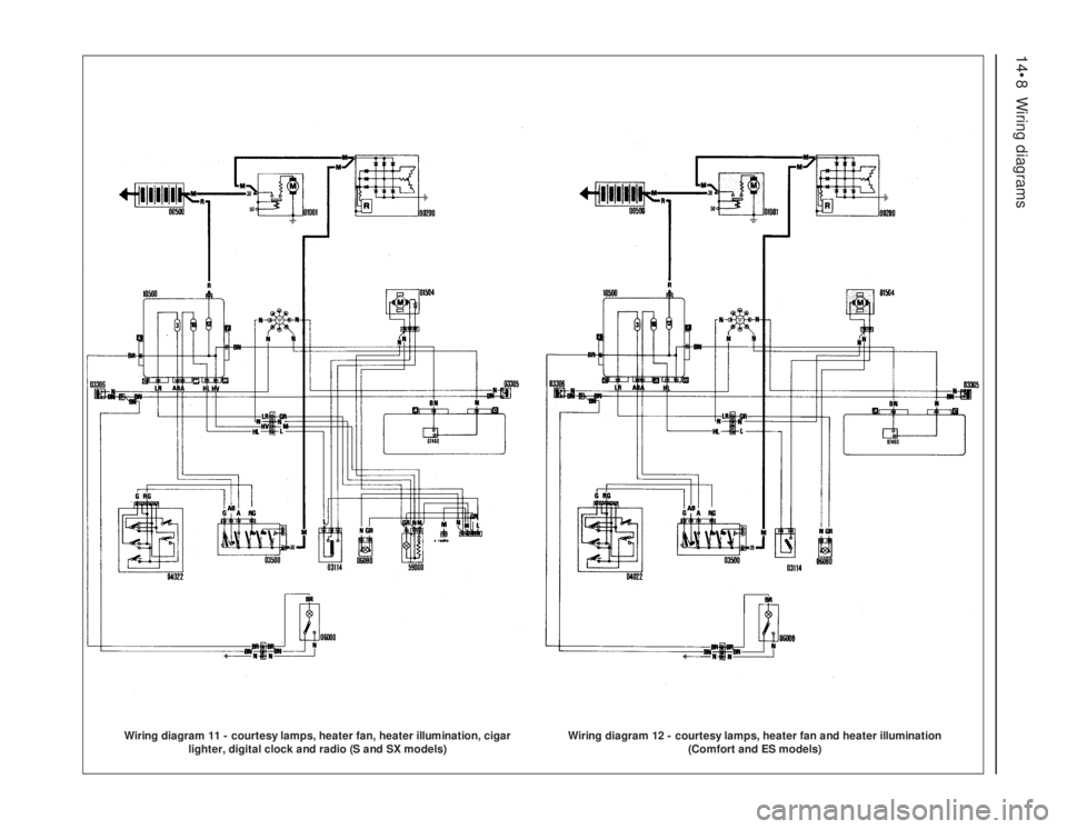
Wiring diagram 11 - courtesy lamps, heater fan, heater illumination, cigar
lighter, digital clock and radio (S and SX models)
Wiring diagram 12 - courtesy lamps, heater fan and heater illumination
(Comfort and ES models)
Page 248 of 303

Wiring diagrams 14•9
14
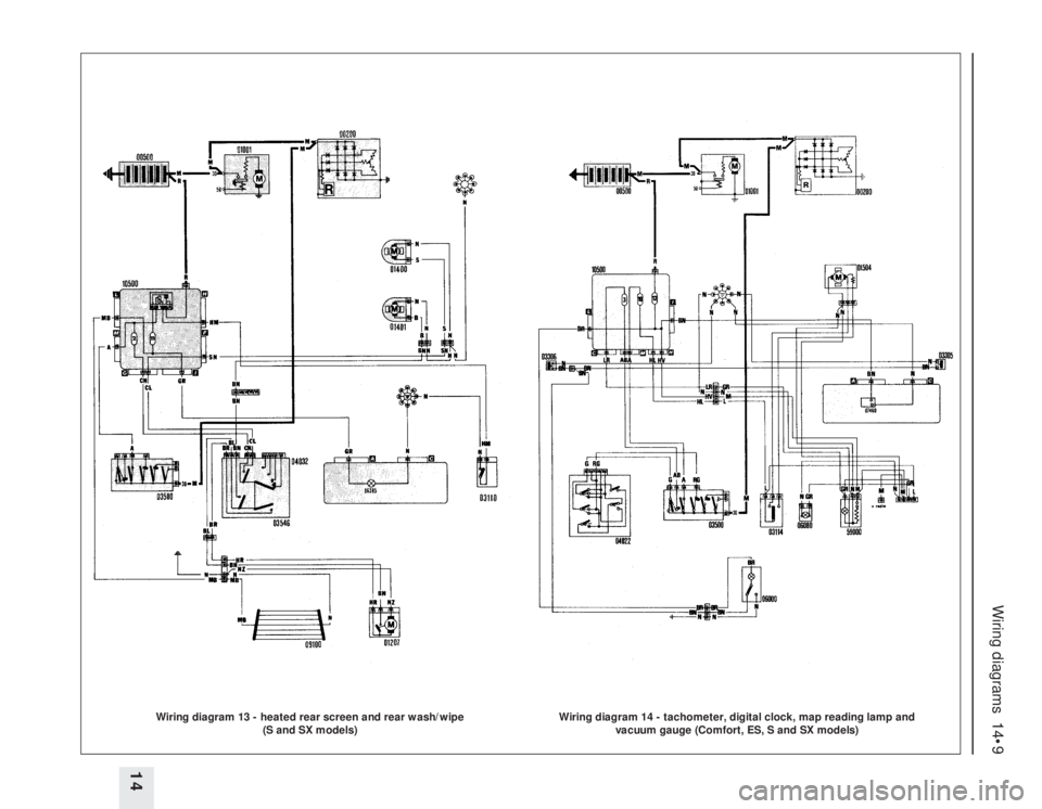
Wiring diagram 13 - heated rear screen and rear wash/wipe
(S and SX models)
Wiring diagram 14 - tachometer, digital clock, map reading lamp and
vacuum gauge (Comfort, ES, S and SX models)
Page 254 of 303

Wiring diagrams 14•15
14
Wiring diagram 22 - direction indicators, hazard warning lamps, brake stop-
lamps, horn and low brake fluid sensor (1301 cc Turbo ie model)
Wiring diagram 23 - courtesy lamps, heater fan, heater illumination, cigar
lighter, digital clock, radio, low oil pressure lamp, oil pressure switch, oil
temperature gauge and tachometer (1301 cc Turbo ie model)