1983 FIAT UNO charging
[x] Cancel search: chargingPage 214 of 303
Ignition unit
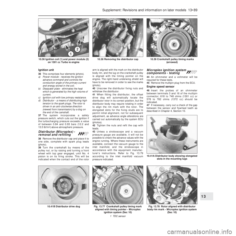
36This comprises four elements (photo).
a) Power module - receives the ignition
advance command and controls the
conduction angle of the primary current
and energy stored in the coil.
b) Dissipater plate - eliminates the heat
which is generated by the high volume of
current.
c) Ignition coil with low primary resistance.
d) Distributor - a means of distributing high
tension to the spark plugs. The rotor is
driven in an anti-clockwise direction
(viewed from transmission) by a dog on
the end of the camshaft.
37The system incorporates a safety
pressure switch, which cuts out the ignition if
the turbocharging pressure exceeds a value
of between 0.84 and 0.93 bars (12.2 and
13.5 lbf/in
2) above atmospheric pressure.
Distributor (Microplex) -
removal and refitting#
38Remove the distributor cap and place it to
one side, complete with spark plug leads
(photo).
39Turn the crankshaft by means of the
pulley nut, or by raising and turning a front
wheel with top gear engaged, until No. 4
piston is on its firing stroke. This will be
indicated when the contact end of the rotorarm is aligned with the mark on the distributor
body rim, and the lug on the crankshaft pulley
is aligned with the timing pointer on the
engine. The right-hand underwing shield will
have to be removed in order to see the marks
(photo).
40Unscrew the distributor fixing nuts and
withdraw the distributor.
41When fitting the distributor, the offset
drive dog will automatically locate the
distributor rotor in its correct position, but the
distributor body may require rotating in order
to align the rim mark with the rotor. The
elongated slots for the fixing studs are to
permit initial alignment, not for subsequent
adjustment, as advance angle alterations are
carried out automatically by the system ECU
(photos).
42Tighten the nuts and refit the cap with
leads.
43Unless a stroboscope and a vacuum
pressure gauge are available, it will not be
possible to check the advance values with the
engine running. Where these instruments are
available, connect the vacuum gauge to the
inlet manifold, and the stroboscope in
accordance with the equipment manufac-
turer’s instructions. Refer to Fig. 13.79
according to the inlet manifold vacuum
pressure indicated.
Microplex ignition system
components - testing ª
44An ohmmeter and a voltmeter will be
required for these tests.
45Remove the multipin plug from the ECU.
Engine speed sensor
46Insert the probes of an ohmmeter
between terminals 3 and 16 of the multipin
connector; 618 to 748 ohms (1301 cc) or
578 to 782 ohms (1372 cc) should be
indicated.
47If necessary, carry out a check of the gap
between the sensor and flywheel teeth as
described in Chapter 4, Section 10.
Supplement: Revisions and information on later models 13•89
10.39 Crankshaft pulley timing marks
(arrowed)10.38 Removing the distributor cap10.36 Ignition coil (1) and power module (2)
on 1301 cc Turbo ie engine
Fig. 13.78 Rotor aligned with distributor
body rim mark - Microplex ignition system
(Sec 10)
10.41A Distributor body showing elongated
slots in the mounting lugs
Fig. 13.77 Crankshaft pulley timing mark
aligned with timing pointer - Microplex
ignition system (Sec 10)
1 TDC sensor10.41B Distributor drive dog
13
Page 215 of 303

TDC sensor
48Insert the probes of the ohmmeter
between terminals 1 and 2 of the multipin
connector; 618 to 748 ohms (1301 cc) or 578
to 782 ohms (1372 cc) should be indicated.
49If necessary, carry out a check of the gap
between the sensor and the crankshaft pulley,
as described in Chapter 4, Section 10.
ECU supply
50Switch on the ignition, and then insert the
probes of a voltmeter between terminals 13
and 11 of the multipin connector. Battery
voltage should be indicated. If not, check the
battery earth, ignition switch or intermediate
connector plug for security.
Power module supply (1301 cc)
51Pull the multipin plug from the powermodule, and connect the probes of a
voltmeter between terminal 4 of the connector
and earth. If the reading is less than battery
voltage, check the security of all connections
between the ignition switch and terminal + 15
of the ignition coil.
52Reconnect the multipin connector to the
ECU, but have the one from the power
module disconnected, and then switch on the
ignition.
53Connect the voltmeter between terminals
4 and 2 of the power module multipin
connector. If the indicated voltage is less than
battery voltage, check the security of all
connections between the ignition switch and
terminal + 15 of the ignition coil, and the
battery earth. If all are satisfactory, check for
continuity between terminals 11 and 12. If
continuity is broken, renew the ECU.
Power module (1372 cc)
54Proceed as described in paragraph 53.
Anti-knock sensor
55If “pinking” occurs, or loss of power is
noticed, test the sensor by substitution of a
new one.
Ignition coil
56Disconnect the leads from terminals 1
and 15 on the coil before testing.
57Using the ohmmeter, check the resistance
of the primary winding. This should be
between 0.31 and 0.37 ohms (1301 cc) or
0.40 to 0.49 ohms (1372 cc), at an ambient
temperature of 20ºC (68ºF).
58The secondary winding resistance should
be between 3330 and 4070 ohms (1301 cc) or
4320 to 5280 ohms (1372 cc), at an ambient
temperature of 20ºC (68ºF).
Distributor
59Check the resistance of the rotor arm,
which should be between 800 and
1200 ohms.
60Where all the foregoing tests have proved
satisfactory, then any problem must be due to
a fault in either the power module or the ECU.
These components can only be checked by
the substitution of a new unit - power module
first, then the ECU.
Safety pressure switch
61The device protects the engine from
excessive turbocharging pressure, cutting off
the ignition by earthing the Microplex ECU.
Testing is not possible without a special
pressure pump, so the easiest way to check a
suspected fault is to fit a new unit.
Digiplex 2 ignition system -
description
62This system operates in a similar manner
to that of the earlier type described in Chap-
ter 4, but the circuit layout differs to suit the
Mono Jetronic fuel injection system. In
operation, the main difference is that the
Digiplex 2 system has a greater number of
13•90 Supplement: Revisions and information on later models
Fig. 13.81 Microplex ignition system
control unit connection (Sec 10)
For colour code, see main wiring diagramsFig. 13.80 Microplex ignition system ECU multipin connector (Sec 10)
For colour code, see main wiring diagrams
Fig. 13.79 Ignition advance curves - Microplex ignition system on the 1301 cc Turbo ie
(Sec 10)
Page 241 of 303

14•2 Wiring diagrams
No Description
06355 Battery charging warning light
06365 Choke warning light
06368 Antiskid system failure lamp
06385 Heated rear screen warning light
06800 Horn
06801 Right horn
06802 Left horn
07000 Coolant level sensor
07001 Engine oil level sensor
07003 Brake fluid level sensor
07015 Right front brake pad wear sensor
07016 Left front brake pad wear sensor
07020 Engine speed sensor
07021 TDC sensor
07022 Anti-knock sensor
07023 Diagnostic socket
07037 Butterfly valve (cut-off) switch
07050 Fuel gauge
07051 Instant fuel consumption gauge (econometer)
07052 Airflow meter
07060 Idle cut-off device
07107 Roadwheel speed sensors
07109 Vacuum switch
07191 Absolute pressure sensor
07192 Vacuum switch
07400 Fuel gauge
07410 Engine oil temperature gauge
07415 Coolant temperature gauge
07420 Engine oil pressure gauge
07430 Tachometer
07460 Clock
07461 Digital clockNo Description
08051 Ignition coil condenser
09000 Dim-dip transformer
09008 Radiator cooling fan 1st speed resistor
09100 Heated rear screen
10022 Cut-off device electronic control unit
10500 Control (fuse) box
10515 Electronic injection control unit
10571 Central locking control unit
10584 Antiskid system ECU
10586 Pressure modulators
59000 Cigar lighter
60000 Instrument panel
60204 Four place fusebox
70090 General earth
70091 General earth
70092 Earth plate
M Electronic control unit
Wire colour codes
A Light blue
B White
C Orange
G Yellow
H Grey
L Blue
M Brown
N Black
R Red
S Pink
V Green
Z Violet
Example of two-colour wire: BN (White/Black) Component key for wiring diagrams 1 to 29 (continued)
Note: Not all the items listed will be fitted to all models
Page 242 of 303
Wiring diagrams 14•3
14
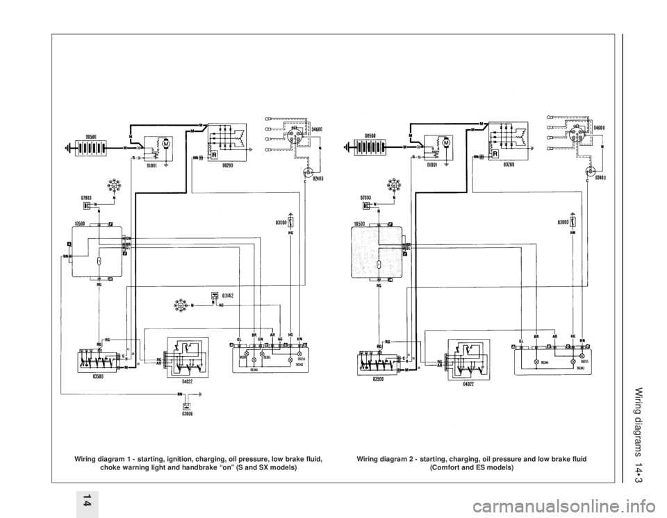
Wiring diagram 1 - starting, ignition, charging, oil pressure, low brake fluid,
choke warning light and handbrake “on” (S and SX models)
Wiring diagram 2 - starting, charging, oil pressure and low brake fluid
(Comfort and ES models)
Page 253 of 303
14•14 Wiring diagrams
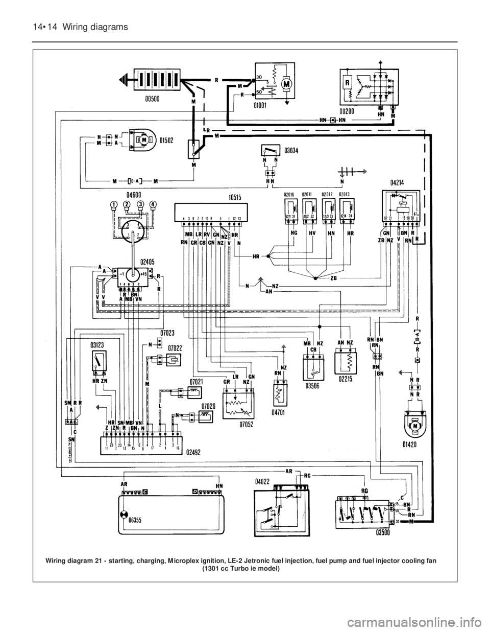
Wiring diagram 21 - starting, charging, Microplex ignition, LE-2 Jetronic fuel injection, fuel pump and fuel injector cooling fan
(1301 cc Turbo ie model)
Page 259 of 303

14•20 Wiring diagrams
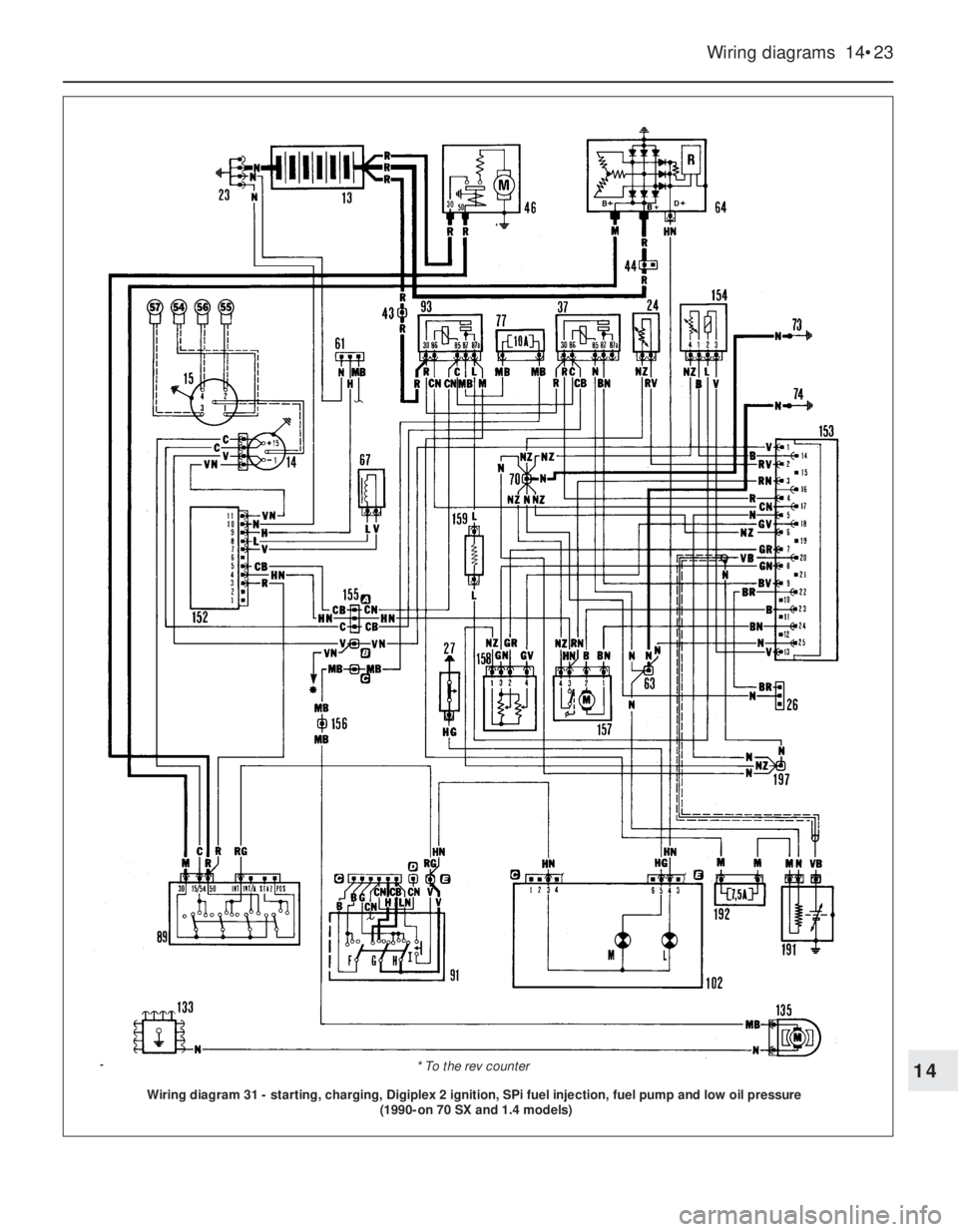
Component key for wiring diagrams 30 to 52
Note: Not all the items listed will be fitted to all models
No Description
1 Injector cooling fan
2 Left front light cluster
3 Left foglamp
4 Left front engine compartment earth
5 Radiator cooling fan
6 Double contact thermostatic switch
on engine radiator
6A Thermostatic switch on engine
radiator
7 Left horn
8 Right horn
9 Resistor for engaging radiator fan 1st
speed
10 Right front light cluster
11 Right foglamp
12 Right front engine compartment earth
13 Battery
14 Ignition coil
15 Ignition distributor with magnetic
impulse generator
16 Left front side direction indicator
17 Ignition power module
18 MPi electronic injection control unit
19 Join between injection/ignition cables
in engine compartment
20 Battery cables join in engine
compartment
21 Antiskid braking system wiring join
22 Starting go-ahead relay
23 Earth for battery
24 Radiator coolant temperature sender
unit for electronic injection
25 Anti-knock sensor
26 Injection system diagnostic socket
27 Switch signalling insufficient engine
oil pressure
28 Radiator coolant temperature sender
unit
29 Engine oil temperature sender unit
30 Engine oil pressure sender unit
31 Right front side direction indicator
32 Engine oil temperature sender unit
cable join
33 Battery recharging signal cable join
34 Windscreen washer pump
35 Rear screen washer pump
36 Reversing switch
37 Fuel injectors relay feed
38 Insufficient brake fluid level sensor
39 Left brake pad wear sensor
40 Microplex electronic ignition control
unit
41 Injection cables join in engine
compartment
42 Ignition cables join in engine
compartment
43 Join between battery cable and
injection cables
44 Join between engine cable and
battery cables
45 Left front brake pad cables join
46 Starter motorNo Description
47 Windscreen wiper motor
48 Headlamp washer pump
49 Fuel injector
50 Fuel injector
51 Fuel injector
52 Fuel injector
53 Supplementary air valve
54 Spark plug
55 Spark plug
56 Spark plug
57 Spark plug
58 Excess supercharging pressure
switch
59 Throttle position switch
60 Engine speed sensor
61 Ignition diagnostic socket
62 Connector block
63 Connector block
64 Alternator
65 Thermostatic switch for injector
cooling fan
66 Right brake pad wear sensor
67 TDC sensor
68 Connector block
69 Connector block
70 Connector block
71 Connector block
72 Join with right brake pad cables
73 Electronic earth
74 Power earth
75 Brake stop-lamp switch
76 20 A fuse for central locking
77 10 A fuse for electric fuel pump
78 30 A fuse for radiator cooling fan
79 30 A fuse for electric windows
80 10 A fuse for injector cooling fan
81 20 A fuse for headlamp
wash/wipe
82 20 A fuse for foglamps
83 Junction box with fuses and relays:
E1 Horn relay (for single tone horns
bridge between 86 and 87)
E2 Heated rear screen relay
E3 Heater (bridge between 85 and 30)
84 Join between front cable and rear
cables
85 Join between front cable and door
ajar sensor cables
86 Earth on dashboard, left hand side
87 Earth on dashboard, right hand
side
88 Choke warning light switch
89 Ignition switch
90 Hazard warning lights switch
91 Steering column switch unit
A Rear screen wash/wipe switch
B Horn button
C Direction indicators switch
D Windscreen wiper intermittent
speed selector switch
E Windscreen/headlamp washer
control switchNo Description
F Rear foglamps/headlamp washer
intermittent device switch
G Headlamp dip switch
H External lights switch
I Flasher switch
92 Foglamp relay
93 Electric fuel pump relay
94 Electric windows relay feed
95 Headlamp wash/wipe intermittent
device
96 Direction indicators/hazard warning
lights flasher unit
97 Central locking receiver
98 Central locking control unit
99 Join with brake pad cables
100 Join between engine cable and
dashboard cables
101 Automatic heater cable join
102 Instrument panel
A Foglamps warning light
B Main beam headlamps warning
light
C Side lights warning light
D Rear foglamps warning light
E Heated rear screen warning light
F Hazard warning lights warning
light
G Direction indicators warning light
H Handbrake applied and insufficient
brake fluid level warning light
I Choke warning light
K Instrument panel light bulbs
L Battery recharging warning light
M Insufficient engine oil pressure
warning light
O Antiskid braking system failure
warning light
P Maximum turbocharging pressure
warning light
Q Brake pad wear warning light
R Door ajar warning light
U Fuel level gauge
V Engine oil pressure gauge
W Engine oil temperature gauge
Y Tachometer
Z Coolant temperature gauge
103 Join with remote control central
locking cables
104 Cigar lighter
105 Radio receiver
106 Heater unit
107 Switch unit
A Heated rear screen switch
B Rear foglamps switch
C Switch unit light bulb
D Rear screen wiper switch
E Foglamps switch
F Clock
108 Left front electric window motor
109 Left front central locking geared
motor
110 Switch signalling left front door ajar
Page 261 of 303
14•22 Wiring diagrams
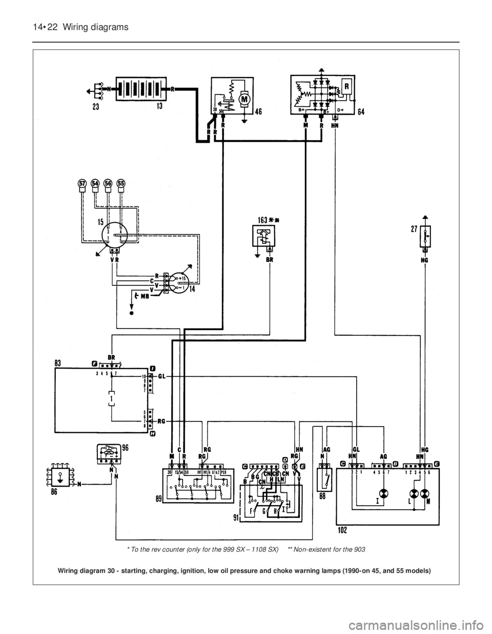
Wiring diagram 30 - starting, charging, ignition, low oil pressure and choke warning lamps (1990-on 45, and 55 models)
* To the rev counter (only for the 999 SX – 1108 SX) ** Non-existent for the 903
Page 262 of 303
Wiring diagrams 14•23
14
Wiring diagram 31 - starting, charging, Digiplex 2 ignition, SPi fuel injection, fuel pump and low oil pressure
(1990-on 70 SX and 1.4 models)
* To the rev counter