1982 VOLVO 940 oil level
[x] Cancel search: oil levelPage 72 of 168
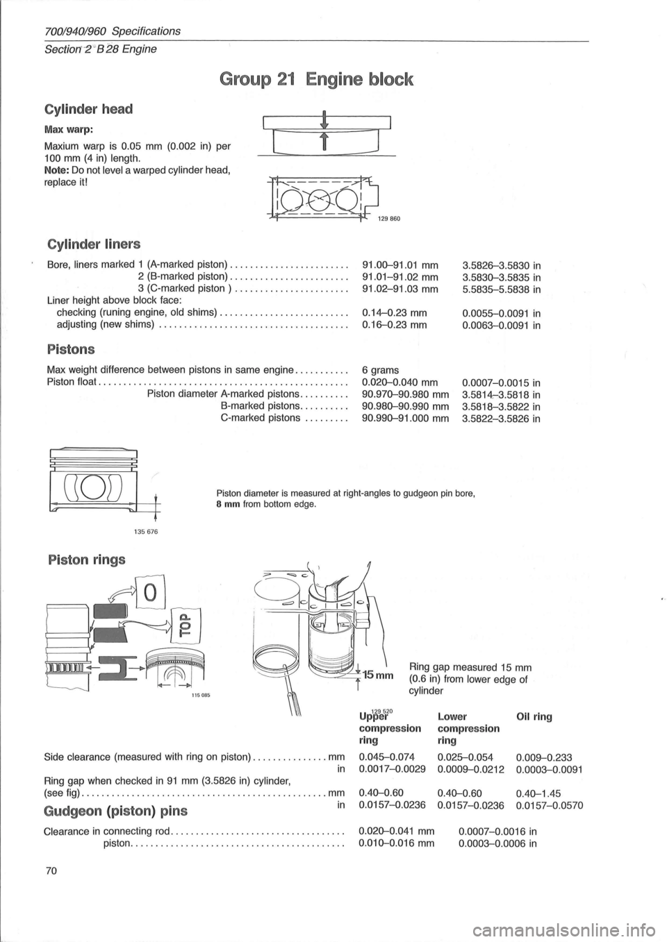
70019401960 Specifications
Section'-2" B 28 Engine
Group 21 Engine block
Cylinder head
Max warp:
Maxium warp is
0.05 mm (0.002 in) per
100 mm (4 in) length.
Note: Do not level a warped cylinder head,
replace it!
Cylinder liners
[
Bore, liners marked 1 (A-marked piston) ....................... .
2 (B-marked piston) ....................... .
3 (C-marked piston) ...................... .
Liner height above
block face:
checking (runing engine,
old shims) ....................... .. .
adjusting (new shims)
..................................... .
Pistons
Max weight difference between pistons in same engine .......... .
Piston
float ................................................. .
Piston diameter A-marked pistons
......... .
B-marked pistons
......... .
C-marked pistons
........ .
]
91.00-91.01 mm
91.01-91.02 mm
91.02-91.03 mm
0.14--0.23 mm
0.16-0.23 mm
6 grams
0.020-0.040 mm
90.970-90.980 mm
90.980-90.990 mm
90.990-91.000 mm
3.5826-3.5830 in
3.5830-3.5835 in
5.5835-5.5838 in
0.0055-0.0091 in
0.0063-0.0091 in
0.0007-0. 0015 in
3.5814-:3.5818 in
3.5818-3.5822 in
3.5822-3.5826 in
((0)) t
'" ~L-f
Piston diameter is measured at right-angles to gudgeon pin bore, S mm from bottom edge.
135676
Piston rings
/,
I 111111111 ~III
'--J 115085
Side clearance (measured with ring on piston) ............... mm
in
Ring gap when checked in 91 mm (3.5826 in) cylinder,
Ring gap measured 15 mm
(0.6 in) from lower edge of
cylinder
U 129520 pper
compression
ring
0.045-0.074
0.0017-0.0029
Lower Oil ring
compression
ring
0.025-0.054 0.009--0.233
0.0009--0.0212 0.0003-0.0091
(see fig) ................................................. mm 0.40-0.60 0.40-0.60 0.40-1.45
in 0.0157-0.0236 0.0157-0.0236 0.0157-0.0570 Gudgeon (piston) pins
Clearance in connecting rod. . . . . . . . . . . . . . . . . . . . . . . . . . . . . . . . . . . 0.020-0.041 mm
piston. . . . . . . . . . . . . . . . . . . . . . . . . . . . . . . . . . . . . . . . . . .
0.010-0.016 mm
70 0.0007-0.0016
in
0.0003-0.0006 in
Page 89 of 168
(
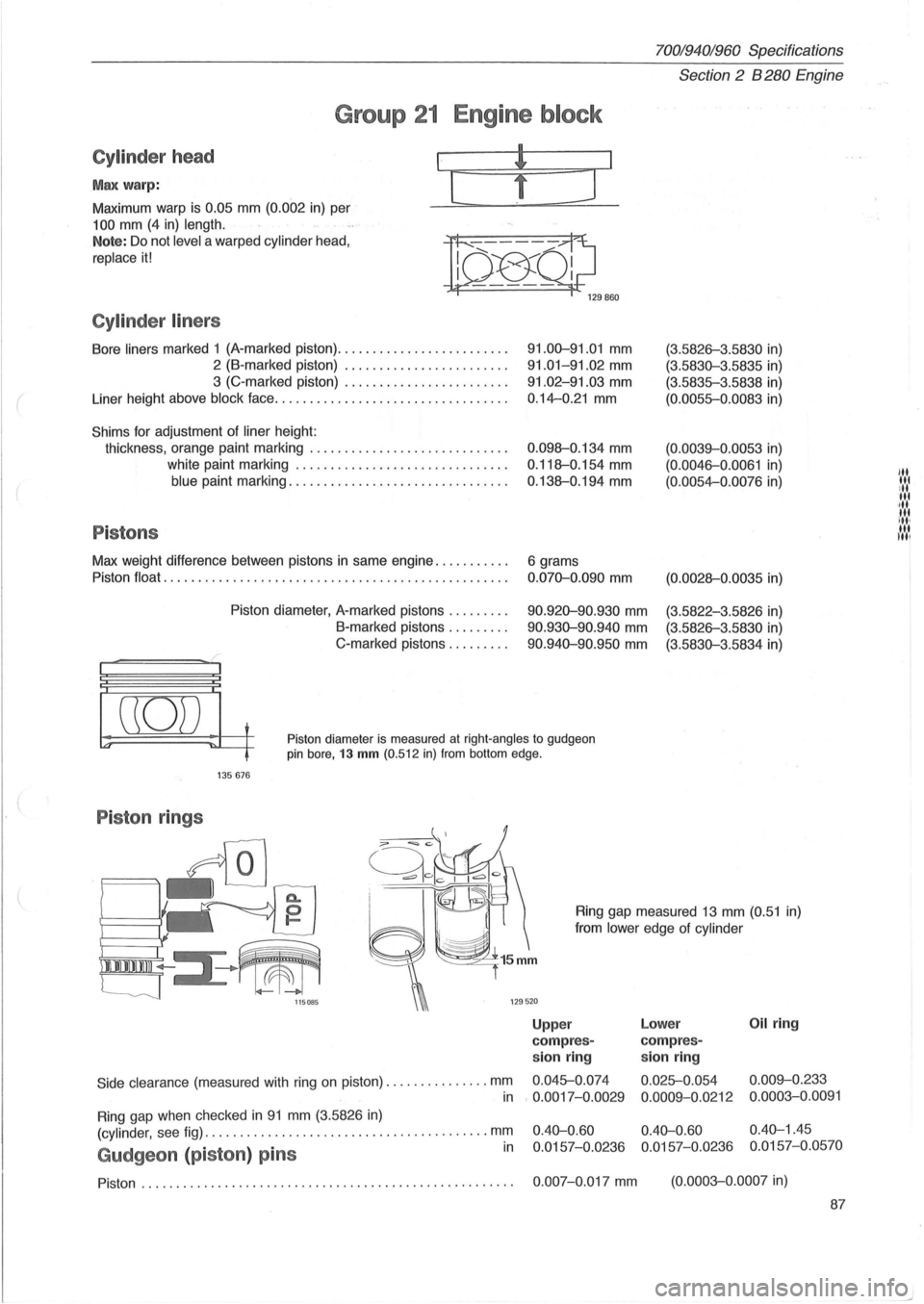
70019401960 Specifications
Section
2 B 280 Engine
Group 21 Engine block
Cylinder head
Max warp:
Maximum warp is 0.05 mm (0.002 in) per
100 mm (4 in) length.
I
[
Note: Do not level a warped cylinder head,
replace it!
n~Ql;J 129860
Cylinder liners
Bore liners marked 1 (A-marked piston) ........................ .
2 (B-marked piston) ....................... .
3 (C-marked piston) ....................... .
Liner height above
block face ................................. .
Shims for adjustment of liner height:
thickness, orange paint marking
............................ .
white paint marking
.............................. .
blue paint marking ............................... .
Pistons
Max weight difference between pistons in same engine .......... .
Piston
float ..................................... ............ .
Piston diameter, A-marked pistons
........ .
B-marked pistons .
....... .
C-marked pistons
........ .
91.00-91.01 mm
91.01-91.02 mm
91.02-91.03 mm
0.14-0.21 mm
0 .098-0.134 mm
0.118-0.154 mm
0.138-0.194 mm
6 grams
0.070-0.090 mm
90.920-90.930 mm
90.930-90.940 mm
90 .940-90.950 mm
(3.5826-3 .5830 in)
(3.5830-3.5835 in)
(3.5835-3.5838 in)
(0.0055-0.0083 in)
(0.0039-0.0053 in)
(0. 0046-0.0061 in)
(0.0054-0.0076 in)
(0.0028-0 .0035 in)
(3.5822-3.5826 in)
(3.5826-3.5830 in)
(3.5830-3.5834 in)
((0)) t
~ ~~ Piston diameter is measured at right-angles to gudgeon pin bore, 13 mm (0.512 in) from bottom edge.
135676
Piston rings
Side clearance (measured with ring on piston) .. ............ . mm
Ring gap measured 13 mm (0.51 in)
from
lower edge of cylinder
Upp er Lower Oil ring
com pres-compres-
sion ring sion ring
0.045-0.
074
0.025-0.054 0.009-0.233
in
Ring gap when checked in 91 mm (3.5826 in)
. 0.0017-0.0029
0.0009-0.0212 0.0003-0.0091
(cylinder,
see fig) ..................................... .... mm
Gudgeon (piston ) pins in
0.40-0.60 0.40-0.60 0.40-1.45
0.0157-0.0236 0.0157-0.0236 0.0157-0.0570
Piston. . . . . . . . . . . . . . . . . . . . . . . . . . . . . . . . . . . . . . . . . . . . . . . . . . . . . . 0.007-0.017 mm (0.0003-0.0007 in)
87
"' lit ill lit ·,11 tit ill, til Itil
Page 130 of 168
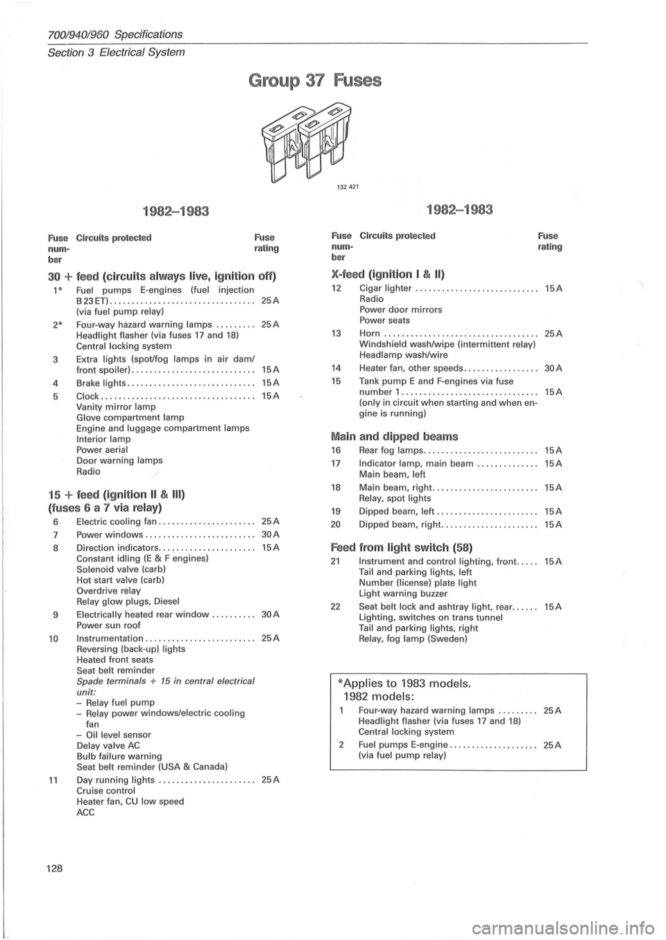
7001940;'960 Specifications
Section 3 Electrical System
Group 37 Fuses
1982-1983
Fu se Circuits protected
num -
ber Fuse
rating
30 + feed (c ir cu its alw ays live, ig nition off)
1 * Fuel pumps E-engines (fuel injection
B23ET) ........................... ...... 25A (via fuel pump relay)
2* Four-way hazard warning lamps ........ . 25A Headlight flasher (via fuses 17 and 18) Central locking system
3 Extra
lights (spot/fog lamps in air dam/
4
5
front spoiler) ............................ 15A
Brake lights ............. ................ 15A
Clock .......................... ......... 15A Vanity mirror lamp
Glove compartment lamp Engine and luggage compartment lamps
Interior lamp
Power aerial Door warning lamps
Radio
15 + feed (ignition II & III)
(fu ses 6 a 7 via relay)
6 Electric cooling fan ...................... 25A
7 Power windows .................. ....... 30A
8 Direction indicators ...................... 15A Constant idling (E & F engines) Solenoid valve (carb)
Hot start valve (carb)
Overdrive relay
Relay glow plugs , Diesel
9 Electrically heated rear window. . . . . . . . .. 30 A
Power sun roof
10 Instrumentation ...................... , .. 25A Reversing (back-up) lights Heated front seats
Seat belt reminder Spade terminals + 15 in central electrical
unit:
-Relay fuel pump -Relay power windows/electric cooling
fan
-Oil level sensor Delay valve AC Bulb failure warning
Seat belt reminder (USA & Canada)
11 Day running lights ...................... 25A Cruise control
128
Heater fan, CU low speed
ACC
1982-1983
Fuse Circuits protected
num -
ber
X-feed (ign ition I & II)
Fuse rating
12 Cigar lighter ... ......................... 15A Radio
Power door mirrors
Power seats
13 Horn ................................ ... 25A Windshield wash/wipe (intermittent relay)
Headlamp wash/wire
14 Heater fan, other speeds. . . . . . . . . . . . . . . .. 30 A
15 Tank pump E and F-engines via fuse number 1 .............................. . (only in circuit when starting and when engine is running)
Ma in and dipped beams
16 Rear fog lamps ......... .................
17 Indicator lamp, main beam .............. Main beam, left
18 Main beam, right. ....................... Relay, spot lights
19 Dipped beam, left .......................
20 Dipped beam, right ......................
Feed from light switch (58 )
15A
15A
15A
15A
15A
15A
21 Instrument and control lighting, front ..... 15A Tail and parking lights, left Number (license) plate light Light warning buzzer
22 Seat belt lock and ashtray light, rear ...... 15A Lighting, switches on trans tunnel
Tail and parking lights, right Relay, fog lamp (Sweden)
* Applies to 1983 models.
1982 models:
Four-way hazard warning lamps ......... 25A Headlight flasher (via fuses 17 and 18) Central locking system
2
Fuel pumps E-engine .................... 25A (via fuel pump relay)
Page 131 of 168
(
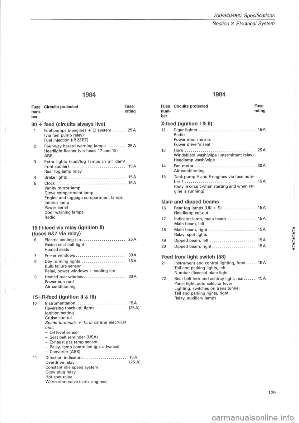
1984
Fuse Circuits protected Fuse
num-rating
ber
30 + feed (circuit s alw ays live)
Fuel pumps E-engines + CI system ....... (via fuel pump relay)
Fuel i njection ((B 23 ET)
2 Four-way
hazard
warning lamps ......... Headlight flasher (via fuses 17 and 18)
ABS
3 Extra lights (spot/fog lamps in
air dam/ front spoiler) . ................ ... .. ......
Rear fog lamp relay
4 Brake lights .....
.. .............•........
5 C lock ....... ............. ............. ..
Vanity mirror lamp Glove compartment lamp Engine and luggage compartment lamps
Interior lamp Power aerial Door warning lamps
Radio
15+I-feed via relay (ignition II)
(fuses 6&7 via relay)
6 Electric cooling fan ................ ...... Fasten seat belt light Heated seats
7
p()\J\; er windows ........... . •.... ........
8 Day
running
lights ..... .......... ....... Bulb failure sensor Relay, power windows + cooling fan
9 Heated
rear
window ................. ....
Power sun roof Air conditioning
15+R-feed (ignition II & III)
10 Instrumentation ........................ .
Reversing (back-up) lights Ignition setting Cruise control
Spade terminals + 15 in central electrical
unit: -Oil level sensor
-Seat belt reminder (USA) -Exhaust gas temp sensor
-Relay, temp contro lled ign. advance)
-Converter (ABS)
25A
25A
15A
15A
15A
25A
30A
15A
30A
15A (25A)
11 Direction indicators.. .. .... .. . .... .. ..... 15A Overdrive relay (25 A) Constant idle speed system Glow plug relay Hot spot relay Warm start-valve (carb. engines)
70019401960 Specifications
Section
3 Electrical System
1984
Fuse C ircuit s protected Fuse
num-rating
ber
X-feed (ignition I & II)
12 Cigar lighter ...... ..............•....... 15A
Radio
Power door mirrors Power driver's seat
13 Horn ...... ........... .. ................ 25A
Windsh ield wash/wipe (interm ittent relay)
Headlamp wash/wipe
14 Fan motor .................. ......... ... 30A
Air conditioning
15 Tank pump E and F-engines via fuse num-ber 1 ...... ...................... ....... 15A
(only in circuit when starting and when en-
gine is running)
Main and dipped beams
16 Rear fog lamps (UK + S) ................ 15A
Headlamp cut-out
17 Indicator lamp, main beam .............. 15A
Main beam , left
18 Main beam, right .......•... ............. 15A IN
Relay, spot lights "I
19 Dipped beam, left ...... ................. 15A IIII( II.
20 D ipped beam, right ...........•.......... 15A "I II. II
Feed from light switch (58)
21 Instrument and control lighting, front ..... 15A
Tail and parking lights, left Number (license) plate light
22 Seat belt lock and ashtray light, rear ...... 15A
Panel light, auto selector lever Lighting, switches on trans tunnel Tail and parking lights, right Relay, auxiliary lamps
129
Page 132 of 168
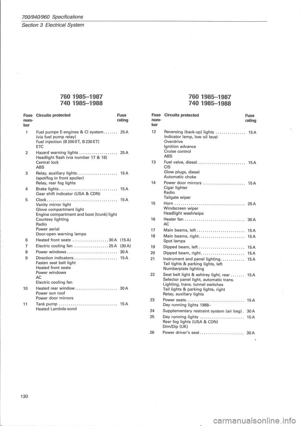
70019401960 Specifications
Section
3 E lectrical System
760 1985-1987 760 1985-1987
740 1985-1988 740 1985-1988
Fuse C ircuit s protected Fuse Fuse Circuits protected
Fuse nurn- r
ating nurn-rating ber ber
Fuel pumps
E-engines & CI system ....... 25A 12 Reversing (back-up) lights ............... 15A
(via fuel pump relay) Indicator lamp, low oil level Fuel injection (B 200 ET, B 230 ET) Overdrive
ETC Ignition advance
2 Hazard
warning
lights ................... 25A Cruise control
Headlight flash
(via number .17 & 18) ABS
Central lock
13 Fuel valve, diesel ........................ 15A ABS CIS
3 Relay, auxiliary lights .................... 15A Glow plugs, diesel
(spot/fog in front spoiler) Automatic choke
Relay , rear fog lights 14 Power door mirrors ..................... 15A
4 Brake lights .
............................ 15A Cigar lighter
Gear shift indicator (USA & CDN) Radio
5
Clock ................................... 15A Tailgate wiper
Vanity mirror light 15 Horn ..... ............................. . 25A
Glove compartment light Windscreen wiper
Engine compartrTJent and boot (trunk) light Headlight wash/wipe
Courtesy lighting 16 Heater fan .............................. 30A Radio AC Power aerial 17 Main beams, left ........................ 15A Door -open warning lamps 18 Main beams, right ....................... 15A 6 Heated
front seats .......... ........ 30 A (15A) Spot
lamps 7 Electric cooling fan ................. 25 A (30A) 19 Dipped beam, left ....................... 15A 8 Power windows ......................... 30A 20 Dipped
beam, right ...................... 15A 9 Direction
indicators ...................... 15A 21 Instrument and panel lighting ............ 15A Fasten seat belt light Tail lights & parking lights, left Heated front seats Numberplate lighting Power windows 22 Seat belt light & ashtray light, rear ....... 15A AC Selector panel light, automatic trans. Electric cooling fan
Lighting, trans. tunnel switches 10 Heated rear window ..................... 30A Tail lights & parking lights, right
Power sun roof Relay , auxiliary lights Power door mirrors 23 Power seats ............................. 15A 11 Tank pump ............................. 15A Day running lights 198B-Heated Lambda-sond 24 Supplementary restraint system (air bag). 30A
25 Day running lights ................... ... 15A Rear fog lights (USA & CDN) Dim/Dip (UK)
26 Power driver's seat ...................... 30A
130
Page 142 of 168
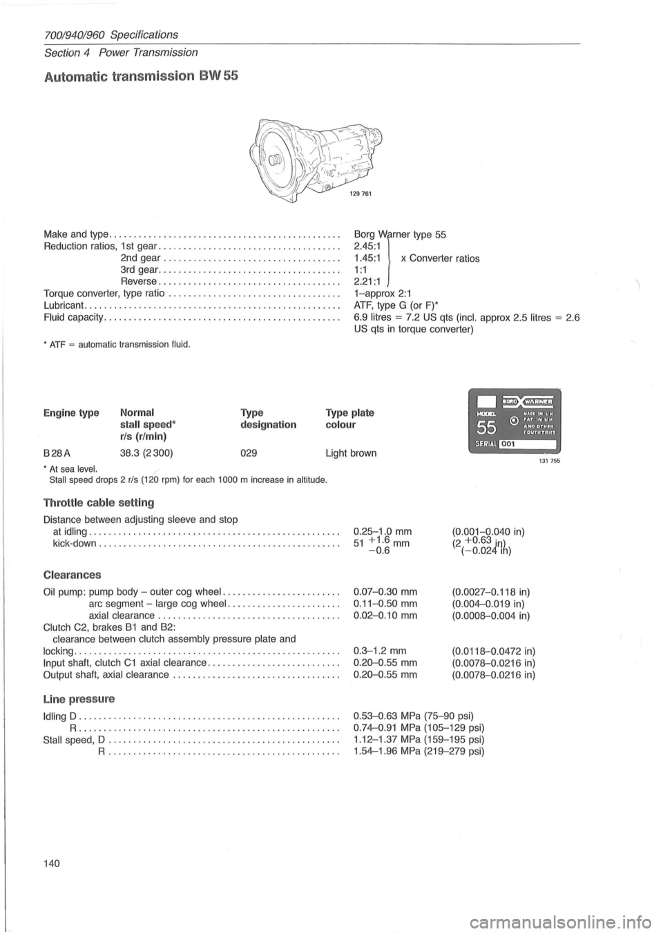
70019401960 Specifications
Section 4 Power Transmission
Automat ic transmission BW 55
Make and type .. ............................................ .
Reduction ratios, 1 st gear ..
................. ................. .
2nd gear
................................... .
3rd gear
................... ................. .
Reverse
.................................... .
Torque converter, type ratio
................................ .. .
Lubricant.
........................... ....................... .
Fluid capacity .................... ........................... .
* ATF = automatic transmission fluid.
1.45:1 x Converter ratios
Borg
Wirner type
55
2.45 :1
1 : 1
2.21 : 1
1-approx 2:1
ATF, type G (or F)*
6.9
litres = 7.2 US qts (inc!. approx 2.5 litres = 2 .6
US qts in torque converter)
.~ Engine type Normal
stall speed*
rls (r/min)
Type
designation
Type plate
colour
....... WAOIIHUH
55 e:> ~~D ~~~I~ f'"OUTUTAUS
B28A 38.3 (2300) 029 SERIAl~ Light brown 131755 * At sea level.
Stall speed drops 2 rls (120 rpm) for each 1000 m increase in altitude .
Throttle cable setting
Distance between adjusting sleeve and stop
at idling .................................................. .
kick -down
........................ ........................ .
C leara nces
Oil pump: pump body -outer cog wheel ....................... .
arc segment -
large cog wheel ...................... .
axial clearance .................................... .
Clutch C2, brakes B1 and B2:
clearance between
clutch assembly pressure plate and
locking ..................................................... .
Input shaft, clutch C1 axial clearance .......................... .
Output shaft,
axial clearance ................................. .
Line pressure
Idling D .................................................... .
R ..................... .... ........................... .
Stall speed, D .................. .............. ...... ........ .
R .............................................. .
140 0.25-1
.0
mm 51 +1.6mm -0.6
0.07-0.30 mm
0.11-0 .50 mm
0.02-0.10 mm
0.3-1 .2 mm
0.20-0 .55 mm
0.20-0.55 mm
(0.001-0.040 in) (2 +0.63 in) (-0.024Ih)
(0.0027-0.118 in)
(0.004-0 .019 in)
(0.0008-0.004 in)
(0.0118-0 .0472 in)
(0.0078-0.0216 in)
(0.0078-0.0216 in)
0.53-0.63 MPa (75-90 psi)
0.74-0.91 MPa (105-129 psi)
1 .12 -1.37
MPa (159-195 psi)
1.54-1.96
MPa (219-279 psi)
Page 151 of 168
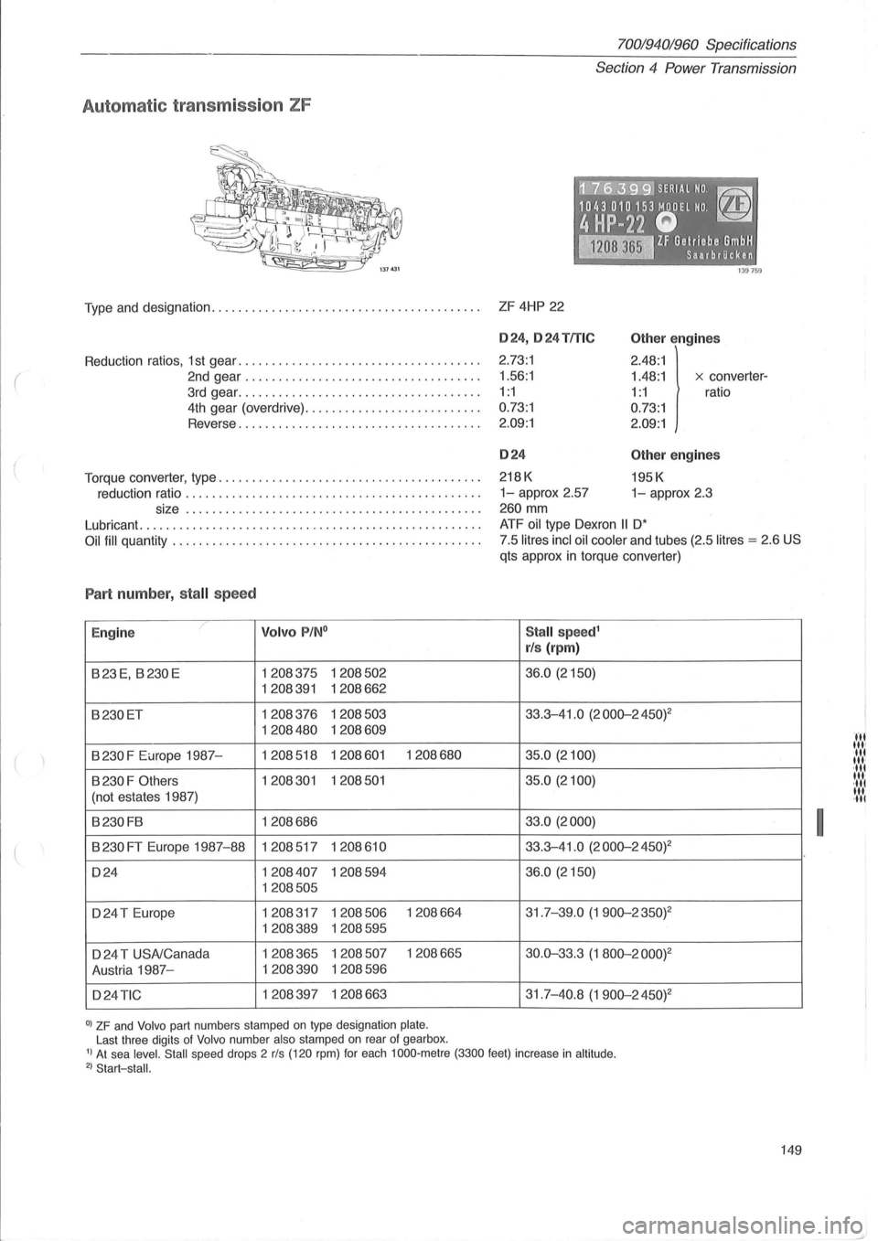
(
Automatic transmission ZF
70019401960 Specifications
Section
4 Power Transmission
·~~7i6~3:9:91 SERI.AL NO. ~
1043010153 MODEL NO. ~
4HP-22 Q -~ IF Gelriebe GmbH ~ Saarbrilcken
Type and designation. . . . . . . . . . . . . . . . . . . . . . . . . . . . . . . . . . . . . . . . . ZF 4HP 22
Reduction ratios, 1 st gear .................................... .
2nd gear ................................... .
3rd gear .................... ................ .
4th gear (overdrive) .......................... .
Reverse
... ................................. .
Torque converter, type
....................................... .
reduction ratio
............................................ .
size
................. ........................... .
Lubricant
.......... ......................................... .
Oil fill quantity ............. ................................. .
Part numb er, stall speed
E ngine ,/ Volvo P/N °
B23E, B230E 1208375 1208502
1208391 1208662
B230ET 1208376 1208503
1208480 1208609
B
230 F Europe 1987-1208518 1208601 1208680
B 230 F Others 1208301 1208501
(not estates 1987)
B230FB 1208686
B 230 FT Europe 1987-88 1208517 1208610
D24 1208407 1208594
1208505
D24 T Europe 1208317 1208506 1208664
1208389 1208595
D 24 T USNCanada 1208365 1208507 1208665
Austria 1987-
1208390 1208596
D24
TIC 1208397 1208663
0) ZF and Volvo part numbers stamped on type designation plate. Last three digits of Volvo number also stamped on rear of gearbox .
024,024 TITle
2.73:1
1.56 :1
1:1
0.73:1
2.09:1
024
218K
Other e ngin es
2.48:1
1.48:1 x converter-
1:1 ratio
0.73:1
2.09:1
Other engin es
195K
1-approx 2.57 1-approx 2.3
260
mm
ATF oil type Dexron II D'
7.5 litres incl oil cooler and tubes (2.5 litres = 2.6 US
qts approx in torque converter)
Stall speed1
rls (rpm )
36.0 (2150)
33.3-41 .0 (2000-2450) 2
35.0 (2100)
35.0 (2100)
33.0 (2000)
33.3-41.0
(2000-2 45W
36.0 (2150)
31.7-39.0 (1900-2350)2
30.0-33.3 (1 800-200W
31.7-40.8 (1900-2450)2
I) At sea level. Stall speed drops 2 rls (120 rpm) for each 1000 ·metre (3300 feet) increase in altitude . 2) Start-stall.
149
I
III til' 'IIt til ' ,lit
lit
,lit til ,III