1982 VOLVO 940 ad blue
[x] Cancel search: ad bluePage 43 of 168
(
70019401960 Specifications
Section
2 B 200, B 230 Engines
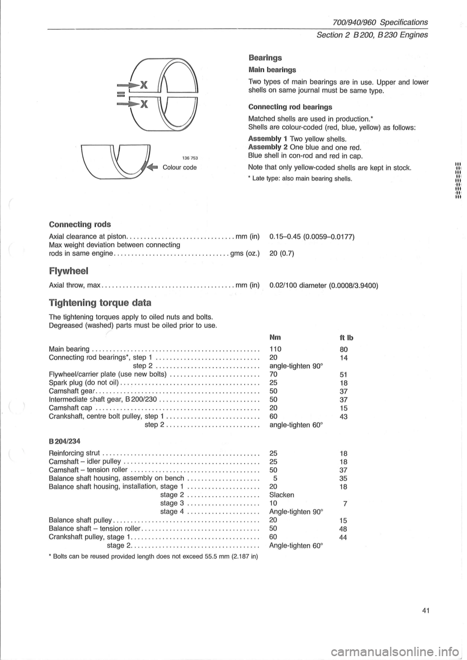
Bea rings
Main bearings
Two types of main bearings are in use. Upper and lower
shells
on same journal must be same type.
Connect
ing rod bearings
Matched
shells are used in production:
Shells are colour -coded (red, blue, yellow) as follows:
136753
Assembly 1 Two yellow shells.
Assembly
2 One blue and one red.
Blue shell in con-rod and red in cap.
Colour code Note that only yellow-coded shells are kept in stock .
• Late type: also main bearing shells .
Connect ing rods
Axial clearance at piston ............................... mm (in) 0.15-0.45 (0.0059-0.0177)
Max weight deviation between connecting
rods
in same engine ................................. gms (oz.) 20 (0.7)
Flywheel
Axial throw, max ...................................... mm (in) 0.021100 diameter (0.0008/3.9400)
Tightening torque data
The tightening torques apply to oiled nuts and bolts.
Oegreased
(washed) parts must be oiled prior to use.
Main bearing
............................................... .
Connecting
rod bearings', step 1 ............................. .
step 2
............................. .
Flywheel/carrier plate (use new bolts) ...................... ... .
Spark plug (do not oil) ....................................... .
Camshaft gear
.............................................. .
Intermediate shaft gear, B 200/230 ............................ .
Camshaft cap
.............................................. .
Crankshaft, centre
bolt pulley, step 1 .......................... .
step 2 .
.. ....................... .
8204/234
Reinforcing strut ............................................ .
Camshaft -
idler pulley ...................................... .
Camshaft -tension
roller .................................... .
Balance shaft housing, assembly on bench .................... .
Balance shaft housing, installation, stage 1 .................... .
stage 2
.................... .
stage 3
.................... .
stage 4
.................... .
Balance shaft pulley ......................................... .
Balance shaft -tension roller .. ............................... .
Crankshaft
pulley, stage 1 .................................... .
stage 2
.................................... .
• Bolts can be reused provided length does not exceed 55.5 mm (2.187 in)
Nm
110
20
angle-tighten 90°
70
25
50
50
20
60
angle-tighten 60°
25
25
50
5
20
Slacken
10
Angle-tighten
90°
20
50
60
Angle-tighten 60°
ftlb
80
14
51
18
37
37
15
43
18
18
37
35
18
7
15
48
44
41
III :11' III II, III 'III III ,11' III
Page 68 of 168
70019401960 Specifications
Section 2 B 200, B 230 Engines
General
Expansion tank
Group 26 Cooling system
128187
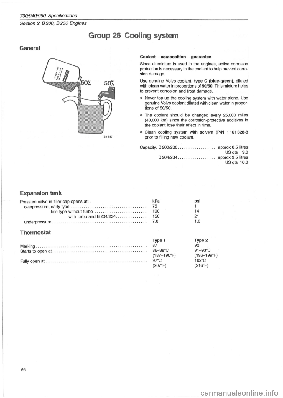
Coolant -composition -guarantee
Since aluminium is used in the engines, active corrosion
protection is necessary
in the coolant to help prevent corro
sion damage.
Use genuine
Volvo coolant, type C (blue-green), diluted
with clean water in proportions of 50/50. This mixture helps
to prevent corrosion and frost damage .
• Never top-up the cooling system with water alone. Use
genuine
Volvo coolant diluted with clean water in propor
tions of 50/50 .
•
The coolant should be changed every 25,000 miles
(40,000
km) since the corrosion -protective additives in
the coolant lose their effect in time.
• Clean cooling system with solvent (P/N 1161328-8
prior to
filling new coolant.
Capacity, B 200/230. . . . . . . . . . . . . . . . . . approx 8.5 litres
US qts 9.0
B 204/234. . . . . . . . . . . . . . . . .. approx 9.5 litres
US qts 10.0
Pressure valve
in filler cap opens at;· . kPa psi
11
14
21
1.0
overpressure, early type .. . . . . . . . . . . . . . . . . . . . . . . . . . . . . . . . . . . 75
late type without turbo . . . . . . . . . . . . . . . . . . . . . . . . . 100
with turbo and B 204/234. . . . . . . . . . . . . . . 150
underpressure . . . . . . . . . . . . . . . . . . . . . . . . . . . . . . . . . . . . . . . . . . . . . 7 .0
Thermostat
Marking ............................ ........................ .
Starts to open
at ......... .............. ..................... .
Fully open at ............................................... .
66
Type 1
87
86-88 °C
(187-190 °
F)
9rC
(20rF)
Type 2
92
91-93°C
( 196-199 °F)
102°C
(216 °
F)
Page 85 of 168
(
General
70019401960 Specifications
Section
2 B 28 Engine
Group 26 Cooling system
128187
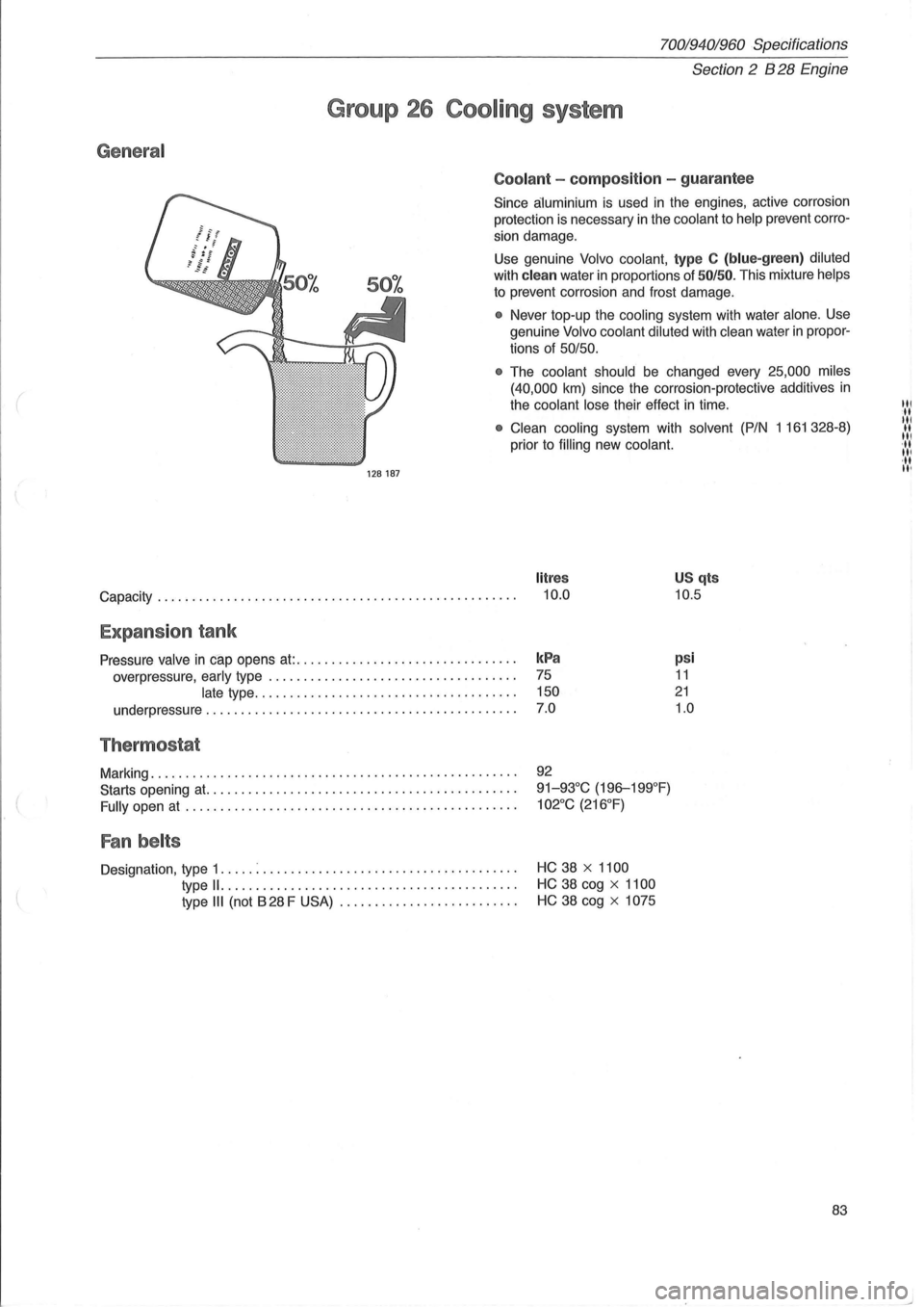
Coolant -composition -guarantee
Since aluminium is used in the engines, active corrosion
protection is necessary
in the coolant to help prevent corro
sion damage .
Use genuine
Volvo coolant, type C (blue-green ) diluted
with clean water in proportions of 50/50. This mixture helps
to prevent corrosion and frost damage.
• Never top-up the cooling system with water alone. Use
genuine
Volvo coolant diluted with clean water in propor
tions of
50/50.
•
The coolant should be changed every 25,000 miles
(40,000
km) since the corrosion-protective additives in
the coolant lose their effect in time.
• Clean cooling system with solvent (P/N 1161328-8)
prior to
filling new coolant.
litres
Capacity. . . . . . . . . . . . . . . . . . . . . . . . . . . . . . . . . . . . . . . . . . . . . . . . . . . . 10.0
US qts
10.5
Expansion tank
Pressure valve in cap opens at:. . . . . . . . . . . . . . . . . . . . . . . . . . . . . . . . kPa
overpressure, early type . . . . . . . . . . . . . . . . . . . . . . . . . . . . . . . . . . . . 75
late type. . . . . . . . . . . . . . . . . . . . . . . . . . . . . . . . . . . . . . 150
underpressure . . . . . . . . . . . . . . . . . . . . . . . . . . . . . . . . . . . . . . . . . . . . .
7.0
Thermostat
Marking .................................................... .
Starts opening
at. ........................................... .
Fully open at ............................................... .
Fan belts
Designation, type 1 ..... : ................................ .... .
type
11. ..................•......•................
type III (not B 28 F USA) ......................... .
92
91-93°C (196-199°F)
102°C (216°F)
HC 38 x 1100
HC 38 cog x 1100
HC 38 cog x 1075
psi
11
21
1.0
83
til ·tt til II III '11 III ·tt II'
Page 89 of 168
(
70019401960 Specifications
Section
2 B 280 Engine
Group 21 Engine block
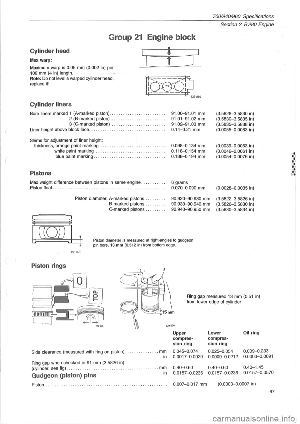
Cylinder head
Max warp:
Maximum warp is 0.05 mm (0.002 in) per
100 mm (4 in) length.
I
[
Note: Do not level a warped cylinder head,
replace it!
n~Ql;J 129860
Cylinder liners
Bore liners marked 1 (A-marked piston) ........................ .
2 (B-marked piston) ....................... .
3 (C-marked piston) ....................... .
Liner height above
block face ................................. .
Shims for adjustment of liner height:
thickness, orange paint marking
............................ .
white paint marking
.............................. .
blue paint marking ............................... .
Pistons
Max weight difference between pistons in same engine .......... .
Piston
float ..................................... ............ .
Piston diameter, A-marked pistons
........ .
B-marked pistons .
....... .
C-marked pistons
........ .
91.00-91.01 mm
91.01-91.02 mm
91.02-91.03 mm
0.14-0.21 mm
0 .098-0.134 mm
0.118-0.154 mm
0.138-0.194 mm
6 grams
0.070-0.090 mm
90.920-90.930 mm
90.930-90.940 mm
90 .940-90.950 mm
(3.5826-3 .5830 in)
(3.5830-3.5835 in)
(3.5835-3.5838 in)
(0.0055-0.0083 in)
(0.0039-0.0053 in)
(0. 0046-0.0061 in)
(0.0054-0.0076 in)
(0.0028-0 .0035 in)
(3.5822-3.5826 in)
(3.5826-3.5830 in)
(3.5830-3.5834 in)
((0)) t
~ ~~ Piston diameter is measured at right-angles to gudgeon pin bore, 13 mm (0.512 in) from bottom edge.
135676
Piston rings
Side clearance (measured with ring on piston) .. ............ . mm
Ring gap measured 13 mm (0.51 in)
from
lower edge of cylinder
Upp er Lower Oil ring
com pres-compres-
sion ring sion ring
0.045-0.
074
0.025-0.054 0.009-0.233
in
Ring gap when checked in 91 mm (3.5826 in)
. 0.0017-0.0029
0.0009-0.0212 0.0003-0.0091
(cylinder,
see fig) ..................................... .... mm
Gudgeon (piston ) pins in
0.40-0.60 0.40-0.60 0.40-1.45
0.0157-0.0236 0.0157-0.0236 0.0157-0.0570
Piston. . . . . . . . . . . . . . . . . . . . . . . . . . . . . . . . . . . . . . . . . . . . . . . . . . . . . . 0.007-0.017 mm (0.0003-0.0007 in)
87
"' lit ill lit ·,11 tit ill, til Itil
Page 98 of 168
70019401960 Specifications
Section
2 B 280 E ngine
General
Group 26 Cooling system
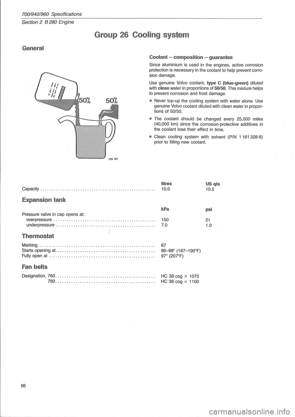
Coolant -compos it ion -gua rantee
Since aluminium is used in ihe engines, active corrosion
protection
is necessary in the coolant to help prevent corro
sion damage.
Use genuine
Volvo coolant, type C (blue-green ) diluted
with clean water in proportions of 50/ 50. This mixture helps
to prevent corrosion and frost damage.
• Never top-up the cooling system with water alone. Use
genuine
Volvo coolant diluted with clean water in propor
tions of
50/50.
•
The coolant should be changed every 25,000 miles
(40,000
km) since the corrosion-protective additives in
the coolant lose their effect in time.
• Clean cooling system with solvent (P/N 1161328-8)
prior to
filling new coolant.
litres
Capacity. . . . . . . . . . . . . . . . . . . . . . . . . . . . . . . . . . . . . . . . . . . . . . . . . . . . 10.0 U S qts
10.5
Expans ion tank
Pressure valve in cap opens at:
overpressure ...................................... .. ..... .
underpressure
............................................ .
Thermostat
Marking .. .................................................. .
Starts opening at. ........................................... .
Fully open at ............................................... .
Fan belts
kPa
150
7.0
87
86-88° (187-190°F)
9l" (20l"F)
Designation, 760. . . . . . . . . . . . . . . . . . . . . . . . . . . . . . . . . . . . . . . . . . . . . HC 38 cog x 1075
780.
. . . . . . . . . . . . . . . . . . . . . . . . . . . . . . . . . . . . . . . . . . . . HC 38 cog x 1100
96
psi
21
1.0
Page 108 of 168
70019401960 Specifications
Section 2 B
6304 Engine
General
Group 26 Cooling System
128187
General
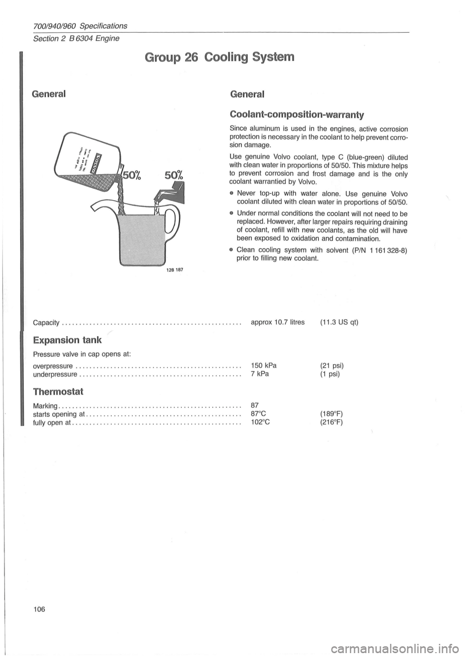
Coolant-com position-warranty
Since aluminum is used in the engines, active corrosion
protection
is necessary in the coolant to help prevent corro
sion damage ,
Use genuine
Volvo coolant, type C (blue-green) diluted
with clean water in proportions of 50/50, This mixture helps
to prevent corrosion and frost damage and is the only
coolant
warrantied by Volvo,
•
Never top-up with water alone, Use genuine Volvo
coolant diluted
with clean water in proportions of 50/50,
• Under normal conditions the coolant will not need to be
replaced, However, after larger repairs requiring draining
of coolant, refill with new coolants, as the old will have
been exposed
to oxidation and contamination ,
• Clean cooling system with solvent (PIN 1161328-8)
prior to
filling new coolant.
Capacity, , , , , , , , . , , , , , , , , , , , , , , , , , , , . , , , , , , , , , . , , . , , , , . , , . , , approx 10,7 litres (11,3 US qt)
Expansion tank
Pressure valve in cap opens at:
overpressure , , , , , , , , , , , , , , , , , , , , . , , , , , , , , , . , , . , , . , , . , , , , , , , ,
underpressure , , , . , , , , ,
.. , , . , , . , , . , , , . , , . , , . , , . , , , , , . , , , , , , , ,
Thermostat
Marking , , , , , , , , , , , , , , , , , , , , , , , , , , , , , , , , , , , , , , , , , , , , , , , , , , , , ,
starts opening
at, , , , , , , , , , , , , . , , , . , , , , , , , , . , , , , , , , , , , , , , , , , , ,
fully open at, , , , , , , , . , , , , , . , , . , , , . , , . , , . , , . , , , , , , , , , , , . , , . , , ,
106 150
kPa
7 kPa
(21 psi)
(1 psi)
Page 119 of 168
(
General
024
Capacity: with manual
gearbox ......... litres (US qts) 9.5
(9.9)
with
aut.
gearbox ......... litres (US qts) 9.2
(9.7)
70019401960 Specifications
Section 2 024, 024 T, 024 TIC Engines
Group 26 Cooling system
128187
024T 024TIC
11.0 11.5
(11.6) (12
.
2)
10.0 11.5
(10.6) (12.2)
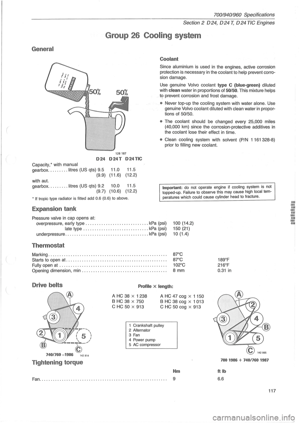
Coolant
Since aluminium is used in the engines, active corrosion
protection is necessary in the
coolant to help prevent corro
sion damage.
Use genuine Volvo coolant type C (blue-green) diluted
with clean water in proportions of 50/50. This mixture helps
to prevent corrosion and frost damage.
• Never top-up the cooling system with water alone . Use
genuine
Volvo coolant diluted with clean water in propor
tions of 50/50.
•
The coolant should be changed every 25,000 miles
(40,000
km) since the corrosion-protective additives in
the coolant lose their effect in time.
• Clean cooling system with solvent (P/N 1 161 328-8)
prior to
filling new coolant.
• If tropic type radiator is filled add 0.6 (0.6) to above.
Important: do not operate engine if cooling system is not topped-up. Failure to observe this may cause high local temperatures which could cause cylinder head to fracture .
Expansion tank /
Pressure valve in cap opens at:
overpressure, early type ............................ kPa (psi)
late type ............................. kPa (psi)
underpressure
............... ...................... kPa (psi)
Thermostat
Marking ..................................................... .
Starts to open
at ............................................ .
Fully open
at ............................................... .
Opening dimension, min ..................................... .
Drive belts Profile x length:
100 (14.2)
150 (21)
10(1.4)
87°C
87 °C
102°C
8 mm
A HC 38 x 1238
B HC 38 x 750
C HC
50 x 913
A HC 47 cog x 1 150
B HC 38 cog x 1 013
C
HC 50 cog x 913
--, / , I 5 I 1 I
--~_/
7401760 -1986 142814
Tightening torque
1 Crankshaft pulley 2 Alternator 3 Fan 4 Power pump
5 AC compressor
Nm
Fan.......................... ............................... 9
189°F
216 °F
0 .
31 in
780 1986 + 7401760 1987
ftlb
6.6
117
lit til' lit ,", ·111 11,1 ·111 1111 ,11'
--'
Page 143 of 168
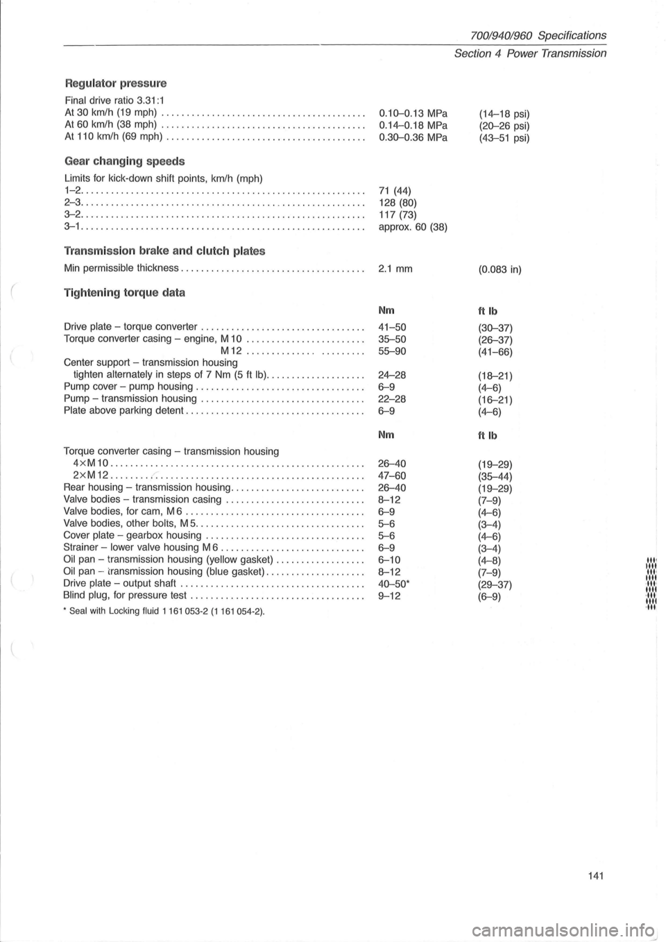
Regulator press ure
Final drive ratio 3.31:1
At 30 km/h (19 mph) ........................................ .
At 60 km/h (38 mph) ....... ................................. .
At 110 km/h (69 mph) ....................................... .
Gea r ch anging speeds
Limits for kick -down shift points , km/h (mph)
1-2 ........................................................ .
2 - 3
......... ............................................... .
3-2 ............................. ........................... .
3-1 ...................................................... .. .
Tran smiss io n brake an d clut ch pla tes
Min permissible thickness .................................. .. .
( Tig ht enin g to rq ue da ta
Drive plate - torque converter ....................... ......... .
Torque converter casing -engine, M
10 ....................... .
M12 ..................... ..
Center support -transmission housing
tighten
alternately in steps of 7 Nm (5 ft Ib) ................... .
Pump cover -pump housing
.................. ............... .
Pump -transmission housing ...
............................. .
Plate above parking detent ............................ .... ... .
Torque converter casing -transmission housing
4 x M
10 .................................................. .
2xM12 ....... . r. ............... ......................... .
Rear housing -transmission housing .......................... .
Valve bodies -transmission casing ........................... .
Valve bodies, for cam, M 6 ................................... .
Valve bodies, other bolis, M 5 ................................. .
Cover
plate - gearbox housing ............................... .
Strainer -
lower valve housing M 6 ......................... ... .
Oil pan - transmission housing (yellow gasket) ................. .
Oil pan -transmission housing (blue gasket) ................... .
Drive
plate - output shaft .... ............................. ... .
Blind plug, for pressure test ....................... .. ......... .
* Seal with Locking fluid 1 161 053-2 (1 161 054-2) .
0.10-0.13 MPa
0.14-0.18 MPa
0.30-0.36 MPa
71 (44)
128
(80)
117 (73)
approx.
60 (38)
2.1 mm
Nm
41-50
35-50 55-90
24-28
6-9
22-28
6-9
Nm
26-40
47 -60
26-40
8-12
6-9
5-6
5-6
6-9
6-10
8-12
40-50·
9-12
70019401960 Specifications
Section 4 Power Transmission
(14-18 psi)
(20-26 psi)
(43-51 psi)
(0.083 in)
ftlb
(30-37)
(26-37)
(41-66)
(18-21 )
(4-6)
(16-21)
(4-6)
ftlb
(19-29)
(35-44)
(19-29)
(7-9)
(4-6)
(3-4)
(4-6)
(3-4)
(4-8)
(7-9)
(29-37)
(6-9)
141
'", "" '", "" ·11"
"" ·11.· 1111 ,11'