1982 VOLVO 940 AUX
[x] Cancel search: AUXPage 25 of 168
(
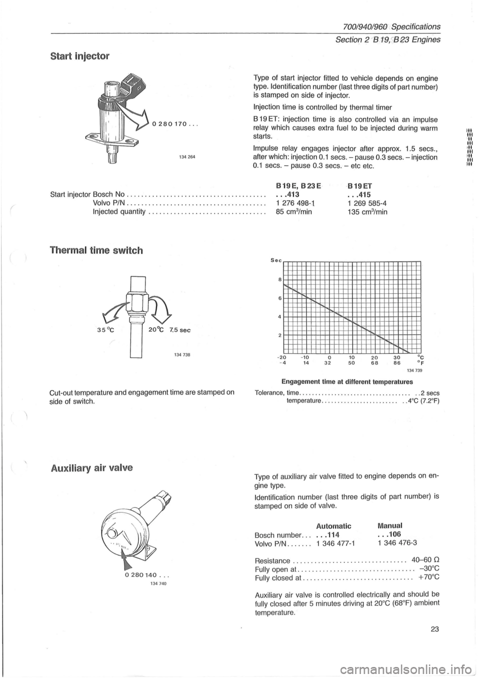
Start injector
0280170 ...
134 264
70019401960 Specifications
Section 2 B1!9,:'B~3 Engines
Type of start injector fitted to vehicle depends on engine
type. Identification number (last three digits of part number)
is stamped on side of injector .
Injection time is controlled by thermal timer
B
19 ET: injection time is also controlled via an impulse
relay which causes extra
fuel to be injected during warm
stqrts.
Impulse
relay engages injector after approx. 1.5 secs.,
after which : injection 0 .1 secs . - pause 0.3 secs. -injection
0.1 secs . -pause 0.3 secs . - etc etc.
Start injector Bosch No ...................................... .
819E, 823 E
. . . 413 819ET
... 415
Volvo PIN ...................................... .
1 276498-1
85 cm3/min
1 269585-4
135 cm3/min Injected quantity ................................ .
Therma l time switch
134738
Cut-out temperature and engagement time are stamped on
side of switch.
Auxiliary air valve
0280140 ...
134740
Sec EEHEEEHEEEl33=EEEEEEEEEEEEE
2 __ _
-
20 -10 0 10 20 30°C - 4 14 32 50 68 86 O F 134739
Engagement time at different temperatures
Tolerance, time. . . . . . . . . . . . . . . . . . . . . . . . . . . . . . . . . .. ..2 secs temperature. . . . . . . . . . . . . . . . . . . . . . .. .. 4 °C (7.2°F)
Type of auxiliary air valve fitted to engine depends on en
gine type.
Identification number (last three digits
of part number) is
stamped on side of valve.
Automatic
Bosch number. .. . . . 114
Volvo PIN ....... 1 346477-1
Manual
... 106
1 346476-3
Resistance . . . . . . . . . . . . . . . . . . . . . . . . . . . . . . .. 40-60 (1
Fully open at. . . . . . . . . . . . . . . . . . . . . . . . . . . . . . . .. -30°C
Fully
closed at . . . . . . . . . . . . . . . . . . . . . . . . . . . . . .. + 70°C
Auxiliary air valve is controlled electrically and should be
fully closed after 5 minutes driving at 20°C (68°F) ambient
temperature.
23
III III '11 II. 'II Nt' U,I
Page 28 of 168

70019401960 Specifications
Section
2 B 19 , B 23 Engines
Start injector
0280170 ...
134 264
Thermal time switch
Cut-out temp Injection time
134738
Auxilary air'valve
0280140 ... 134740
Coolant temperature sensor
0280130 ... 135791
Bosch number. . . . . . . . . . . . . . . . . . . . . . . . . . . . .. 026
Volvo PIN ............................... 1 332 396-9
Resistance at:
-1Ooe (- 14 °F) ................... 8260-105600
+20oe (68 °F) ...................... 2280-27200
+80oe (175 °F) ................ ........ 290 -364 0
26
Bosch number ............ .
Volvo PIN ................. .
Injected quantity ........... .
Injection time controlled by t~
Sec J+:q:::q:::q:::q:::m
8 i-+-'f-+-I-H-+++++
6 I-+-H-H"-H-H-H
4 f-+-IH--t-++++++
-20 -4 -10 14
Injection timl
Tolerance, time ....... .
temperature.
Bosch number .....
Volvo PIN, early typ
late type
Resistance ...... .
Fully open at ... .
Fully closed at .. .
The
auxiliary air v
be fully closed afl
bient temperaturf
-2
Page 51 of 168
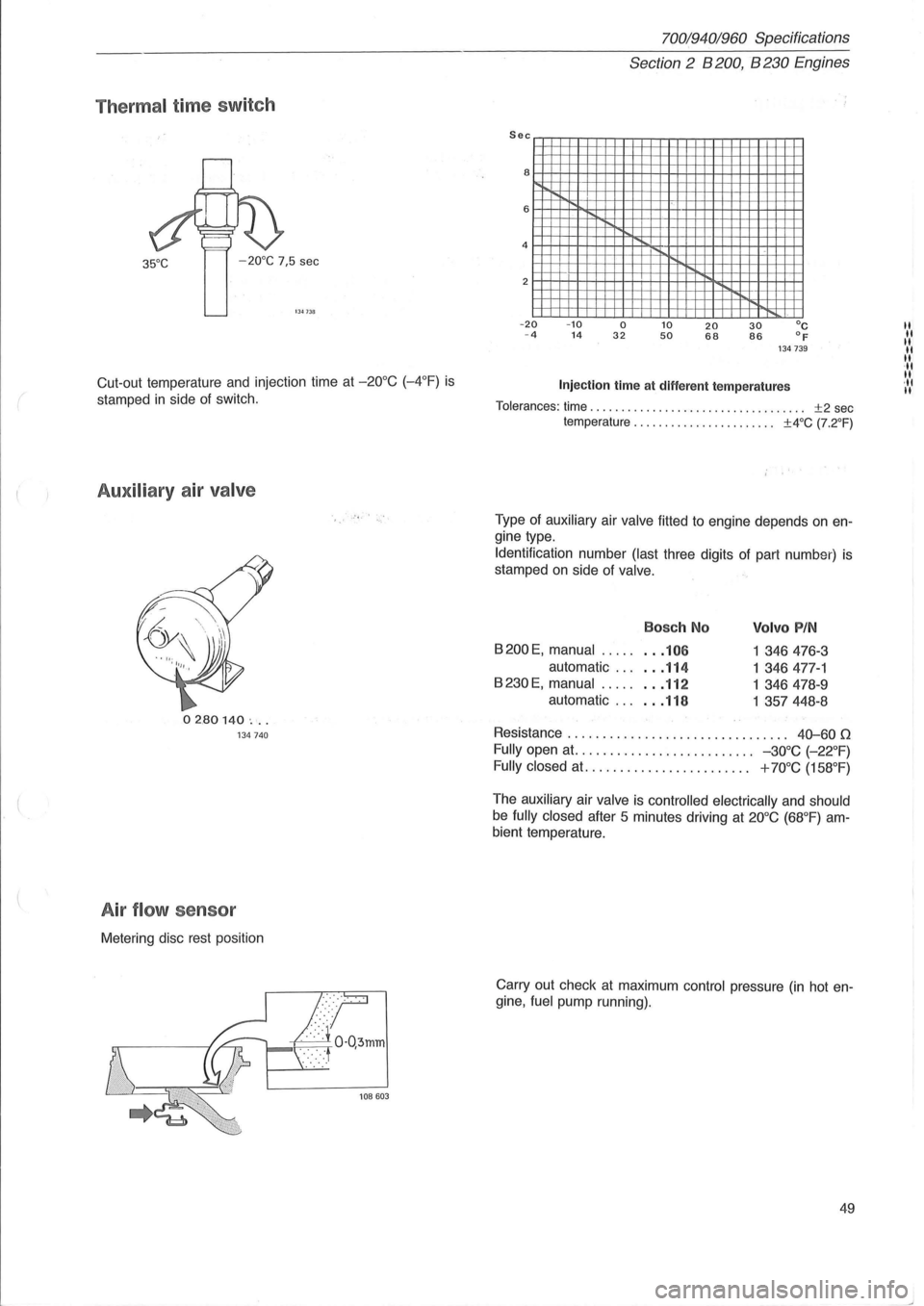
Thermal time sw itch
35°C -20°C 7,5 sec
1 341111
Cut -out temperature and injection time at -20°C (-4°F) is
stamped in side of switch.
Auxiliary air valve
02.80140 ' ... 134740
A ir flow se nsor
Metering disc rest position
.• -'j,' ,.,'
70019401960 Specifications
Section
2 B 200, B 230 Engines
2mmmwm_
-20 -10 0 10 20 30°C -4 14 32 50 68 86 of 134739
Injection time at different temperatures
Tolerances: time. . . . . . . . . . . . . . . . . . . . . . . . . . . . . . . . . . . ±2 sec temperature. . . . . . . . . . . . . . . . . . . . . .. ±4°C (7.2°F)
Type of auxiliary air valve fitted to engine depends on en
gine type.
Identification number
(last three digits of part number) is
stamped
on side of valve.
Bosch No
8200 E, manual ..... . .. 106
automatic . .. . .. 114
8230E, manual ........ 112
automatic . .. . .. 118
Volvo PIN
1 346476-3
1 346477-1
1
346478- 9
1 357448-8
Resistance . . . . . . . . . . . . . . . . . . . . . . . . . . . . . .
.. 40-60 0
Fully open at. . . . . . . . . . . . . . . . . . . . . . . . . . -30°C (-22°F)
Fully closed
at. . . . . . . . . . . . . . . . . . . . . . .. + 70°C (158°F)
The auxiliary air valve is controlled electrically and should
be fully closed after 5 minutes driving at 20°C (68°F) am
bient temperature.
Carry out check
at maximum control pressure (in hot en
gine , fuel pump running).
49
"
"
" II
" . "
" ·11 II
Page 81 of 168
(
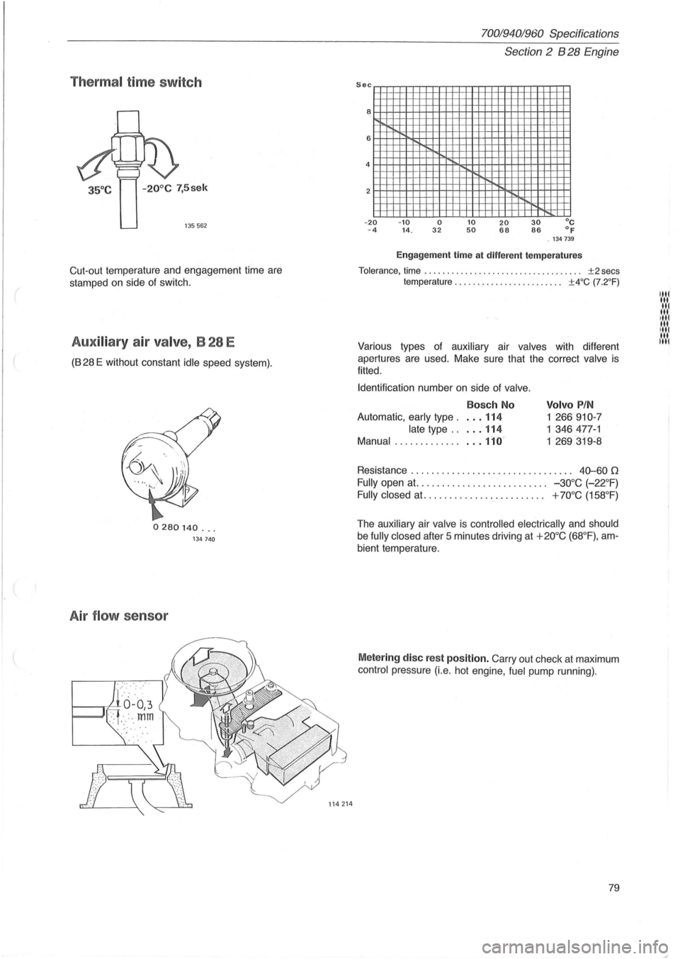
Thermal time switch
-20° C 7,5sek
135562
Cut-out temperature and engagement time are
stamped on side
of switch.
Aux iliary air valve, B 28 E
(828 E without constant idle speed system) .
0280140 ... 134740
Air flow sensor
70019401960 Specifications
Section
2 B 28 Engine
Sec
8
6
4
2
- .20 - 4 -10 14. o 32 10 50 20 68 30 86 ° C of . 134739
Engagement time at different temperatures
Tolerance, time. . . . . . . . . . . . . . . . . . . . . . . . . . . . . . . . . .. ±2 secs
temperature . . . . . . . . . . . . . . . . . . . . . . .. ±4°C (7.2 °F)
Various types of auxiliary air valves with different
apertures are
used. Make sure that the correct valve is
fitted .
Identification number
on side of valve .
Bosch No
Automatic, early type. . .. 114
late type .. . .. 114
Manual ................ 110'
Volvo PIN
1 266910-7
1 346477-1
1
269319~8
Resistance . . . . . . . . . . . . . . . . . . . . . . . . . . . . . . . . 40--60 0
Fully open at. . . . . . . . . . . . . . . . . . . . . . . . .. -30°C (-22°F)
Fully closed at. ............ '. ' . . . . . . . .. + 70°C (158 °F)
The auxiliary air valve is controlled electrically and should
be fully closed after 5 minutes driving at +20°C (68 °F), am
bient temperature.
Metering disc rest position. Carry out check at maximum
control pressure (i.e. hot engine, fuel pump running).
79
Page 131 of 168
(
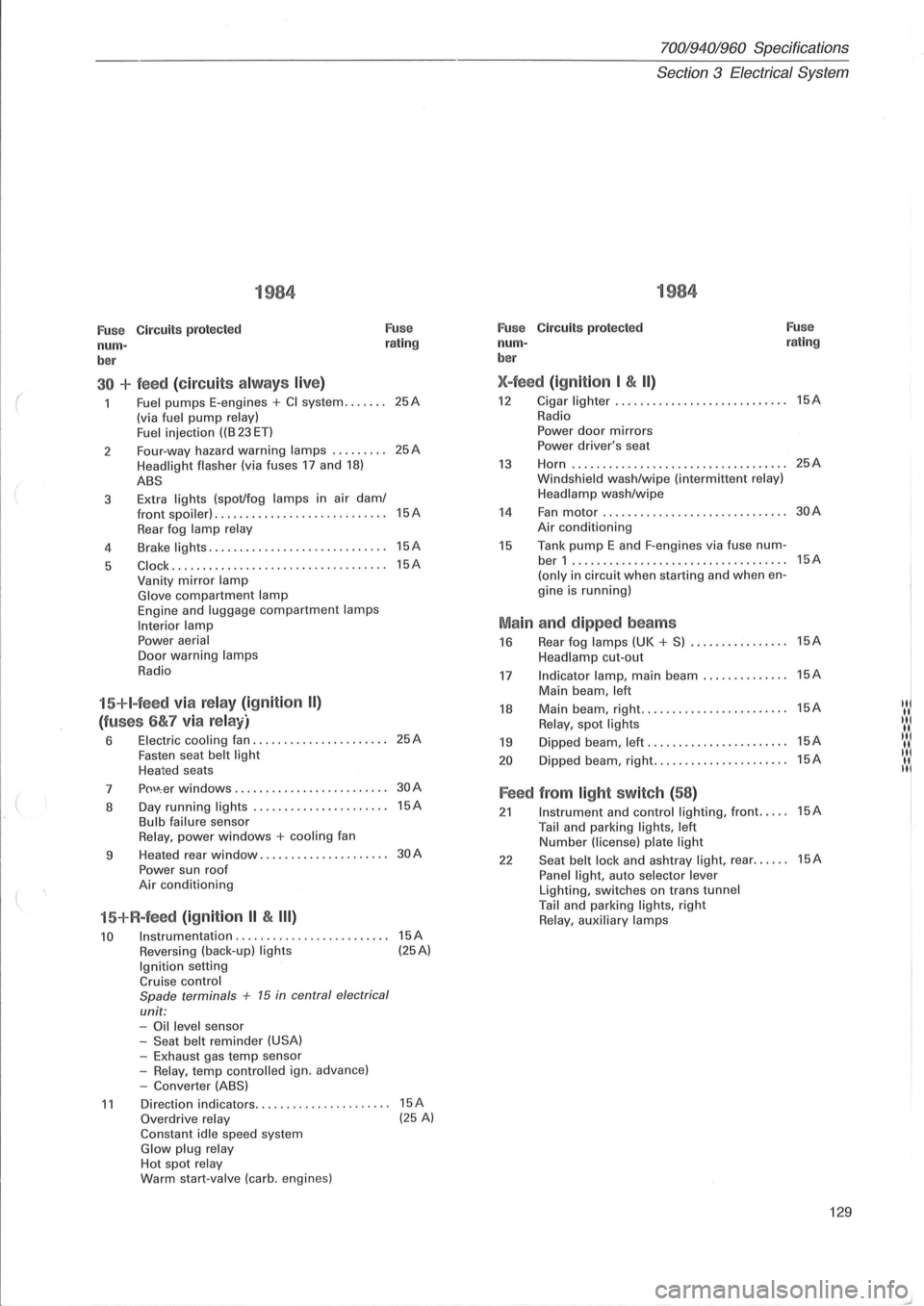
1984
Fuse Circuits protected Fuse
num-rating
ber
30 + feed (circuit s alw ays live)
Fuel pumps E-engines + CI system ....... (via fuel pump relay)
Fuel i njection ((B 23 ET)
2 Four-way
hazard
warning lamps ......... Headlight flasher (via fuses 17 and 18)
ABS
3 Extra lights (spot/fog lamps in
air dam/ front spoiler) . ................ ... .. ......
Rear fog lamp relay
4 Brake lights .....
.. .............•........
5 C lock ....... ............. ............. ..
Vanity mirror lamp Glove compartment lamp Engine and luggage compartment lamps
Interior lamp Power aerial Door warning lamps
Radio
15+I-feed via relay (ignition II)
(fuses 6&7 via relay)
6 Electric cooling fan ................ ...... Fasten seat belt light Heated seats
7
p()\J\; er windows ........... . •.... ........
8 Day
running
lights ..... .......... ....... Bulb failure sensor Relay, power windows + cooling fan
9 Heated
rear
window ................. ....
Power sun roof Air conditioning
15+R-feed (ignition II & III)
10 Instrumentation ........................ .
Reversing (back-up) lights Ignition setting Cruise control
Spade terminals + 15 in central electrical
unit: -Oil level sensor
-Seat belt reminder (USA) -Exhaust gas temp sensor
-Relay, temp contro lled ign. advance)
-Converter (ABS)
25A
25A
15A
15A
15A
25A
30A
15A
30A
15A (25A)
11 Direction indicators.. .. .... .. . .... .. ..... 15A Overdrive relay (25 A) Constant idle speed system Glow plug relay Hot spot relay Warm start-valve (carb. engines)
70019401960 Specifications
Section
3 Electrical System
1984
Fuse C ircuit s protected Fuse
num-rating
ber
X-feed (ignition I & II)
12 Cigar lighter ...... ..............•....... 15A
Radio
Power door mirrors Power driver's seat
13 Horn ...... ........... .. ................ 25A
Windsh ield wash/wipe (interm ittent relay)
Headlamp wash/wipe
14 Fan motor .................. ......... ... 30A
Air conditioning
15 Tank pump E and F-engines via fuse num-ber 1 ...... ...................... ....... 15A
(only in circuit when starting and when en-
gine is running)
Main and dipped beams
16 Rear fog lamps (UK + S) ................ 15A
Headlamp cut-out
17 Indicator lamp, main beam .............. 15A
Main beam , left
18 Main beam, right .......•... ............. 15A IN
Relay, spot lights "I
19 Dipped beam, left ...... ................. 15A IIII( II.
20 D ipped beam, right ...........•.......... 15A "I II. II
Feed from light switch (58)
21 Instrument and control lighting, front ..... 15A
Tail and parking lights, left Number (license) plate light
22 Seat belt lock and ashtray light, rear ...... 15A
Panel light, auto selector lever Lighting, switches on trans tunnel Tail and parking lights, right Relay, auxiliary lamps
129
Page 132 of 168
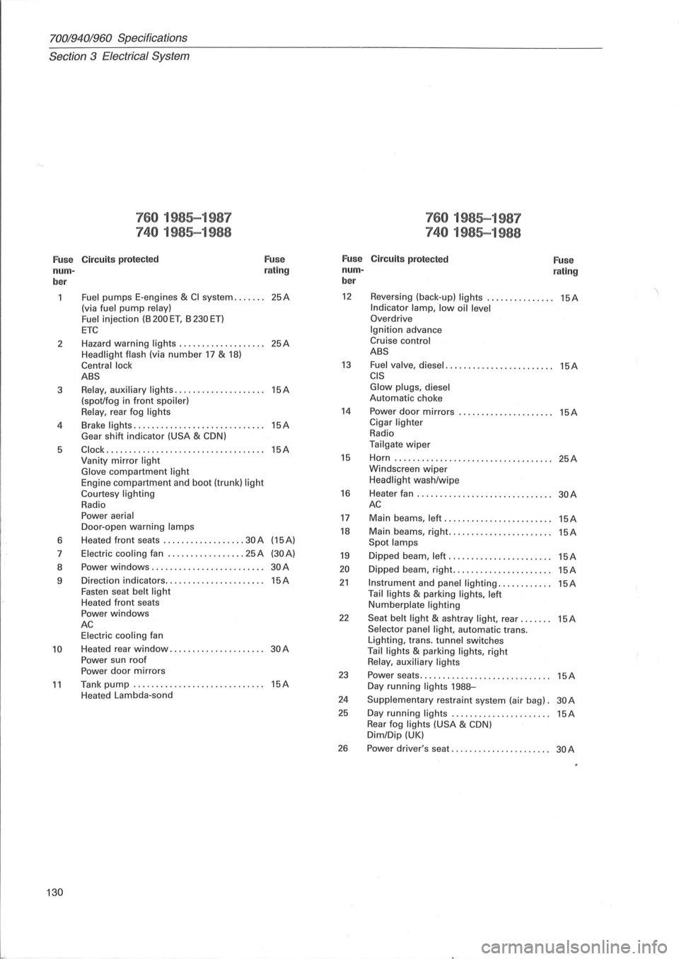
70019401960 Specifications
Section
3 E lectrical System
760 1985-1987 760 1985-1987
740 1985-1988 740 1985-1988
Fuse C ircuit s protected Fuse Fuse Circuits protected
Fuse nurn- r
ating nurn-rating ber ber
Fuel pumps
E-engines & CI system ....... 25A 12 Reversing (back-up) lights ............... 15A
(via fuel pump relay) Indicator lamp, low oil level Fuel injection (B 200 ET, B 230 ET) Overdrive
ETC Ignition advance
2 Hazard
warning
lights ................... 25A Cruise control
Headlight flash
(via number .17 & 18) ABS
Central lock
13 Fuel valve, diesel ........................ 15A ABS CIS
3 Relay, auxiliary lights .................... 15A Glow plugs, diesel
(spot/fog in front spoiler) Automatic choke
Relay , rear fog lights 14 Power door mirrors ..................... 15A
4 Brake lights .
............................ 15A Cigar lighter
Gear shift indicator (USA & CDN) Radio
5
Clock ................................... 15A Tailgate wiper
Vanity mirror light 15 Horn ..... ............................. . 25A
Glove compartment light Windscreen wiper
Engine compartrTJent and boot (trunk) light Headlight wash/wipe
Courtesy lighting 16 Heater fan .............................. 30A Radio AC Power aerial 17 Main beams, left ........................ 15A Door -open warning lamps 18 Main beams, right ....................... 15A 6 Heated
front seats .......... ........ 30 A (15A) Spot
lamps 7 Electric cooling fan ................. 25 A (30A) 19 Dipped beam, left ....................... 15A 8 Power windows ......................... 30A 20 Dipped
beam, right ...................... 15A 9 Direction
indicators ...................... 15A 21 Instrument and panel lighting ............ 15A Fasten seat belt light Tail lights & parking lights, left Heated front seats Numberplate lighting Power windows 22 Seat belt light & ashtray light, rear ....... 15A AC Selector panel light, automatic trans. Electric cooling fan
Lighting, trans. tunnel switches 10 Heated rear window ..................... 30A Tail lights & parking lights, right
Power sun roof Relay , auxiliary lights Power door mirrors 23 Power seats ............................. 15A 11 Tank pump ............................. 15A Day running lights 198B-Heated Lambda-sond 24 Supplementary restraint system (air bag). 30A
25 Day running lights ................... ... 15A Rear fog lights (USA & CDN) Dim/Dip (UK)
26 Power driver's seat ...................... 30A
130
Page 133 of 168
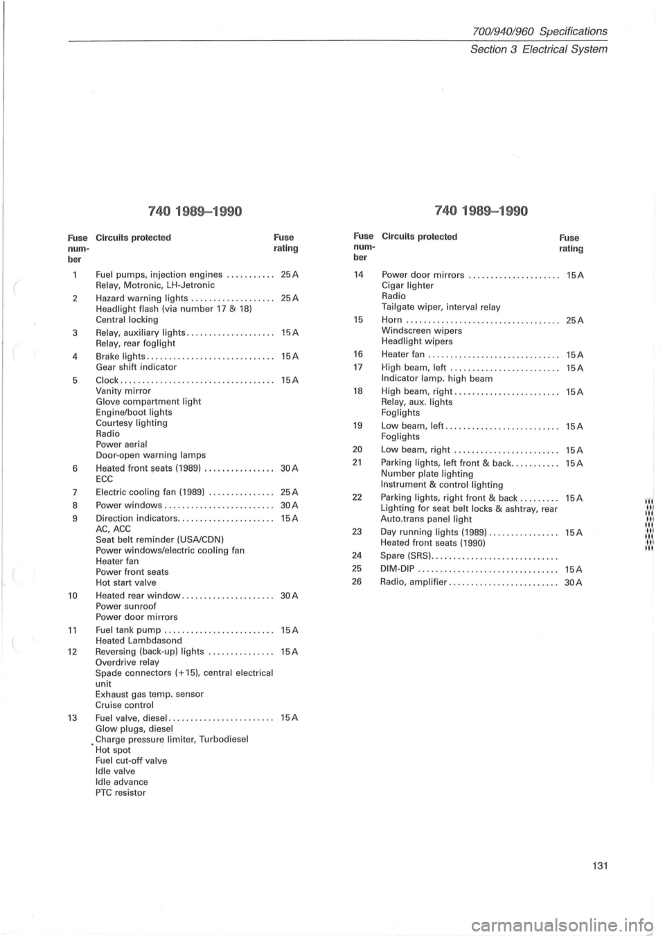
70019401960 Specifications
Section
3 Electrical System
740 1989-1990 740 1989-1990
Fu se Circuit
s prot ect ed F
u se F
u se
Circuit s protected
Fu se
nurn - r
a ting nurn
-
rating
ber b
er
Fuel pumps, injection engines ........... 25A 14 Power door mirrors ..................... 15A
( Relay , Motronic, LH-Jetronic Cigar lighter
2 Hazard
warning lights
................... 25A Radio
Headlight
flash (via number 17 & 18) Tailgate wiper, interval relay
Central locking 15 Horn ..... .......................... .. .. 25A
3 Relay , auxiliary li ghts ............. ....... 15A Windscreen wipers
Relay, rear foglight Headlight wipers
4 Brake
lights
...................... ....... 15A 16 Heater fan .............................. 15A
Gear shift indicator 17 High beam , left ........... .............. 15A
5 Clock ................................ ... 15A Indi cator lamp. high beam
Vanity
mirror 18 High beam, right ...................... .. 15A Glove compartment light Relay, aux . lights
Engine/boot lights
Foglights
Courtesy lighting
19 Low beam, left ................. ......... 15A Radio Foglights Power aerial 20 Low beam, right ................. ....... 15A Door -open warning lamps
6 Heated front seats
(1989) ................ 30A 21 Parking lights, left front & back ........... 15A
ECC Number plate lighting
7 Electric
cooling fan (1989)
............... 25A Instrument & control lighting
22 Parking lights, right front & back ......... 15A fn' 8 Power windows .
................... ..... 30A Lighting for seat belt locks & ashtray, rear III III 9 Direction
indicators ...................... 15A Auto.trans panel light III III AC,ACC 23 Day running lights (1989) ................ 15A '111 Seat belt reminder (USA/CDN) III Heated front seats (1990) ·111 Power windows/electric cooling fan III
Heater fan 24 Spare (SRS) .............................
Power front seats 25 DIM-DiP .. ..............•............... 15A
Hot start valve 26 Radio , amplifier ............... .......... 30A
10 Heated rear window ................. .... 30A Power sunroof
Power door mirrors
11 Fuel tank pump . .. ............. ......... 15A Heated Lambdasond
12 Reversing (back-up) lights ..... .... ...... 15A Overdrive relay
Spade connec tors (+15), central electrical
unit Exhaust gas temp. sensor
Cruise control
13 Fuel valve, diesel ..................... ... 15A Glow plugs, diesel • Charge pressure limiter, Turbodiesel
Hot spot
Fuel cut-off valve
Idle valve Idle advance PTC resistor
131
Page 138 of 168
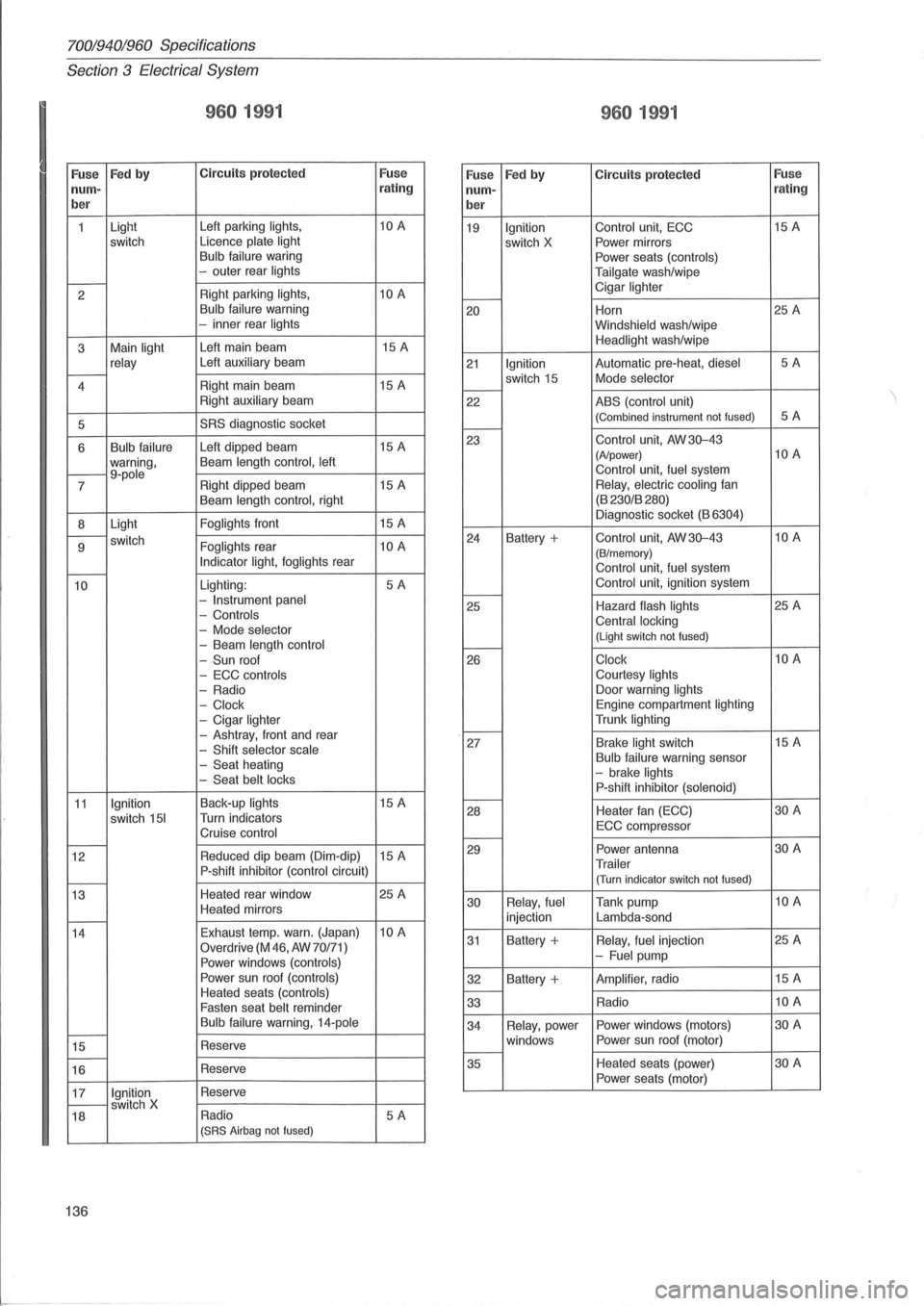
70019401960 Specifications
Section
3 E lectrical System
I
960 1991
Fuse Fed by C ircuit s protecte d Fuse
960 1991
Fuse Fed by Circuit s protected Fuse nurn-rating nurn- r
ating
b er
ber
1 Light
Left
parking lights, 10 A
19 Ignition Control unit, ECC 15
A
switch Licence plate
light switch X Power
mirrors Bulb failure waring
Power seats (controls)
-outer rear lights
Tailgate wash/wipe t---2 Right
parking lights, 10 A Cigar lighter I----Bulb failure
warning 20 Horn 25
A -inner rear lights
Windshield wash/wipe
3 Main
light Left
main beam 15
A Headlight wash /wipe
relay Left auxiliary beam 21 Ignition Automatic pre-heat, diesel 5A r---4 Right
main beam 15 A switch
15 Mode selector I----Right auxiliary beam
22 ABS (control unit)
5
SRS diagnostic socket (Combined instrument not fused) 5A I----
6 Bulb failure Left dipped beam 15
A
warning , Beam length
control, left t---9-pole 7 Right
dipped beam 15
A 23
Control unit, AW 30-43 (A/power) 10 A
Control unit, fuel system Relay,
electric cooling fan
Beam length control, right (B
230/B 280)
8 Light
Foglights front
15 A Diagnostic
socket (B 6304)
r---switch
9 Foglights rear 10 A Indicator light, foglights rear -
24 Battery + Control unit, AW 30-43 10 A
(B/m emory) Control unit , fuel system
10 Lighting : 5A -Instrument panel
- Controls
-
Mode selector
-Beam length control Control
unit
, ignition system t---25 Hazard flash lights 25 A Central locking (Light switch not fused) I-----(Sun roof
26 Clock 10 A
-
ECC controls Courtesy lights
-Radio Door
warning lights
- Clock Engine compartment lighting
-Cigar lighter Trunk lighting
-Ashtray, front and rear -Shift selector scale
- Seat heating -Seat belt locks
I----27 Brake light switch 15
A Bulb failure warning sensor -brake lights P-shift inhibitor (solenoid)
11 Ignition Back-up lights 15 A
switch
151 Turn indicators
Cruise control
I----28 Heater
fan (ECC) 30 A
ECC compr essor t---t---12 Reduced
dip beam (Dim-dip) 15 A
P-shift inhibitor (control circuit) r---
29 Power antenna 30 A
Trailer (Turn indicator switch not fused)
13 Heated
rear window 25 A
Heated mirrors
t---
30 Relay,
fuel Tank pump 10 A
injection Lambda-sond
14 Exhaust
temp. warn. (Japan)
10 A
Overdrive
(M 46, AW 70/71)
Power windows (controls)
31 Battery + Relay, fuel injection 25
A -Fuel pump
Power sun roof
(controls) 32 Battery + Amplifier, radio 15
A
Heated seats (controls) Fasten seat belt reminder
I----33 Radio 10 A
Bulb
failure warning, 14-pole t---15 Reserve t---16 Reserve 3
4
Relay , power Power
windows (motors) 30 A
windows Power
sun roof (motor)
t---35 Heated
seats (power) 30 A
Power seats (motor)
17
Ignition Reserve t---switch X
18 Radio 5A (SRS
Airbag not fused)
136