1982 VOLVO 700 oil type
[x] Cancel search: oil typePage 142 of 168

70019401960 Specifications
Section 4 Power Transmission
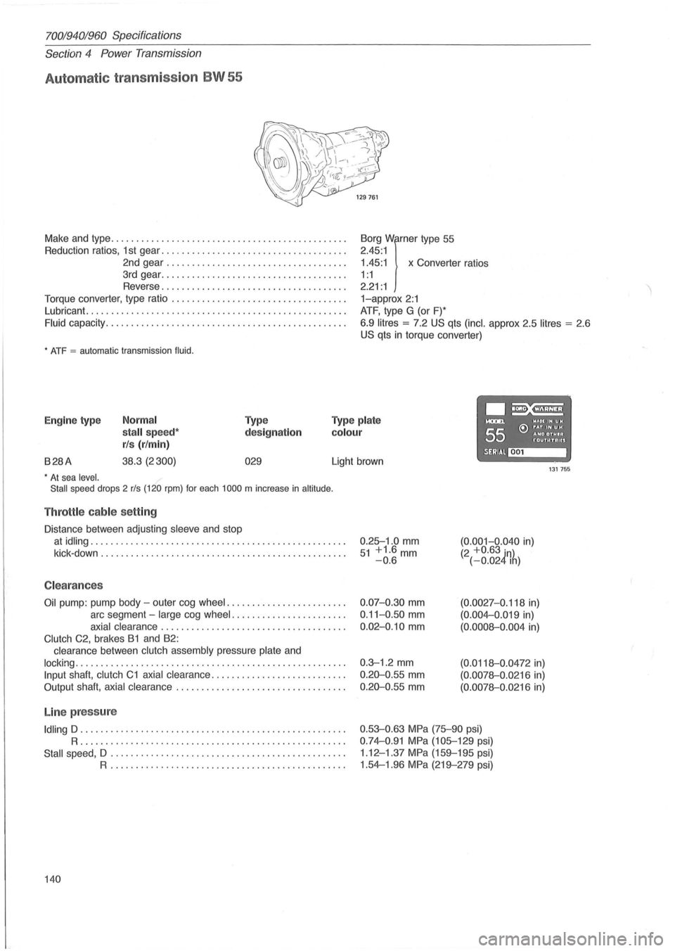
Automat ic transmission BW 55
Make and type .. ............................................ .
Reduction ratios, 1 st gear ..
................. ................. .
2nd gear
................................... .
3rd gear
................... ................. .
Reverse
.................................... .
Torque converter, type ratio
................................ .. .
Lubricant.
........................... ....................... .
Fluid capacity .................... ........................... .
* ATF = automatic transmission fluid.
1.45:1 x Converter ratios
Borg
Wirner type
55
2.45 :1
1 : 1
2.21 : 1
1-approx 2:1
ATF, type G (or F)*
6.9
litres = 7.2 US qts (inc!. approx 2.5 litres = 2 .6
US qts in torque converter)
.~ Engine type Normal
stall speed*
rls (r/min)
Type
designation
Type plate
colour
....... WAOIIHUH
55 e:> ~~D ~~~I~ f'"OUTUTAUS
B28A 38.3 (2300) 029 SERIAl~ Light brown 131755 * At sea level.
Stall speed drops 2 rls (120 rpm) for each 1000 m increase in altitude .
Throttle cable setting
Distance between adjusting sleeve and stop
at idling .................................................. .
kick -down
........................ ........................ .
C leara nces
Oil pump: pump body -outer cog wheel ....................... .
arc segment -
large cog wheel ...................... .
axial clearance .................................... .
Clutch C2, brakes B1 and B2:
clearance between
clutch assembly pressure plate and
locking ..................................................... .
Input shaft, clutch C1 axial clearance .......................... .
Output shaft,
axial clearance ................................. .
Line pressure
Idling D .................................................... .
R ..................... .... ........................... .
Stall speed, D .................. .............. ...... ........ .
R .............................................. .
140 0.25-1
.0
mm 51 +1.6mm -0.6
0.07-0.30 mm
0.11-0 .50 mm
0.02-0.10 mm
0.3-1 .2 mm
0.20-0 .55 mm
0.20-0.55 mm
(0.001-0.040 in) (2 +0.63 in) (-0.024Ih)
(0.0027-0.118 in)
(0.004-0 .019 in)
(0.0008-0.004 in)
(0.0118-0 .0472 in)
(0.0078-0.0216 in)
(0.0078-0.0216 in)
0.53-0.63 MPa (75-90 psi)
0.74-0.91 MPa (105-129 psi)
1 .12 -1.37
MPa (159-195 psi)
1.54-1.96
MPa (219-279 psi)
Page 151 of 168

(
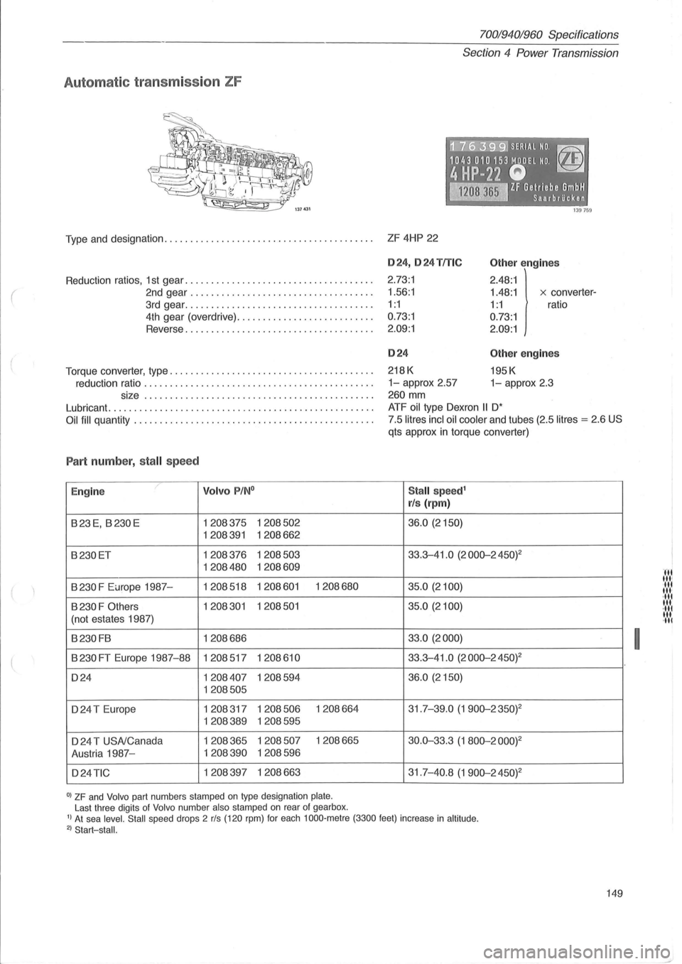
Automatic transmission ZF
70019401960 Specifications
Section
4 Power Transmission
·~~7i6~3:9:91 SERI.AL NO. ~
1043010153 MODEL NO. ~
4HP-22 Q -~ IF Gelriebe GmbH ~ Saarbrilcken
Type and designation. . . . . . . . . . . . . . . . . . . . . . . . . . . . . . . . . . . . . . . . . ZF 4HP 22
Reduction ratios, 1 st gear .................................... .
2nd gear ................................... .
3rd gear .................... ................ .
4th gear (overdrive) .......................... .
Reverse
... ................................. .
Torque converter, type
....................................... .
reduction ratio
............................................ .
size
................. ........................... .
Lubricant
.......... ......................................... .
Oil fill quantity ............. ................................. .
Part numb er, stall speed
E ngine ,/ Volvo P/N °
B23E, B230E 1208375 1208502
1208391 1208662
B230ET 1208376 1208503
1208480 1208609
B
230 F Europe 1987-1208518 1208601 1208680
B 230 F Others 1208301 1208501
(not estates 1987)
B230FB 1208686
B 230 FT Europe 1987-88 1208517 1208610
D24 1208407 1208594
1208505
D24 T Europe 1208317 1208506 1208664
1208389 1208595
D 24 T USNCanada 1208365 1208507 1208665
Austria 1987-
1208390 1208596
D24
TIC 1208397 1208663
0) ZF and Volvo part numbers stamped on type designation plate. Last three digits of Volvo number also stamped on rear of gearbox .
024,024 TITle
2.73:1
1.56 :1
1:1
0.73:1
2.09:1
024
218K
Other e ngin es
2.48:1
1.48:1 x converter-
1:1 ratio
0.73:1
2.09:1
Other engin es
195K
1-approx 2.57 1-approx 2.3
260
mm
ATF oil type Dexron II D'
7.5 litres incl oil cooler and tubes (2.5 litres = 2.6 US
qts approx in torque converter)
Stall speed1
rls (rpm )
36.0 (2150)
33.3-41 .0 (2000-2450) 2
35.0 (2100)
35.0 (2100)
33.0 (2000)
33.3-41.0
(2000-2 45W
36.0 (2150)
31.7-39.0 (1900-2350)2
30.0-33.3 (1 800-200W
31.7-40.8 (1900-2450)2
I) At sea level. Stall speed drops 2 rls (120 rpm) for each 1000 ·metre (3300 feet) increase in altitude . 2) Start-stall.
149
I
III til' 'IIt til ' ,lit
lit
,lit til ,III
Page 162 of 168

700/940/960 Specifications
Section 8 Body and interior
Section 8 Body and interior
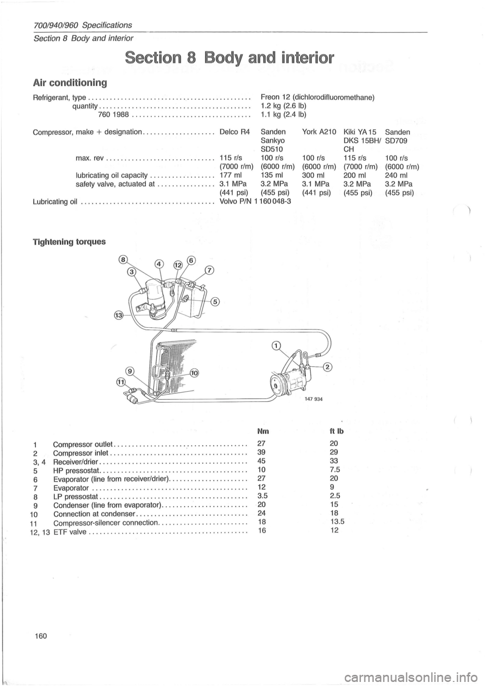
Air condition ing
Refrigerant, type ............ ..................... ........... .
quantity .
........................................ .
7601988 ............ ......... ......... .. .
Compressor, make
+ designation .................... Delco R4
Freon 12 (dichlorodifluoromethane)
1.2 kg (2.6 Ib)
1 .1 kg (2.4lb)
Sanden
York A210 Kiki YA 15 Sanden
Sankyo
OKS 15BHI S0709
S0510
CH
max. rev ......................... . .... 115 rls 100 rls 100 rls 115 rls 100 rls
(7000 rIm) (6000 rIm) (6000 rIm) (7000 rIm) (6000 rIm)
lubricating oil capacity .................. 177 ml 135 ml 300 ml 200 ml 240 ml
safety valve, actuated at ................ 3.1 MPa 3.2 MPa 3.1 MPa
3.2 MPa 3
.2 MPa
(441 psi) (455 psi) (441 psi) (455 psi) (455 psi)
Lubricating
oil . .................................... Volvo PIN 1 160048-3
T ightening torques
Nm ftlb
1 Compressor outlet .................... .' ............... . 27 20
2 Compressor inlet ............................ ......... . 39 29
3, 4 Receiver/drier .............. .......................... . 45 33
5 HP pressostat. ....................................... . 10 7.5
6 Evaporator
(line from receiver/drier) ........... .... ...... . 27 20
7 Evaporator ............. .................... ......... . 12 9
8
LP pressostat ............. ........................ ... . 3.5
2.5
9 Condenser
(line from evaporator) ....................... . 20 15
10 Connection at condenser .............................. . 24 18
11 Compressor-silencer connection ........................ .
12, 13 ETF valve ......... .................................. .
18 13.5
16 12
160
Page 163 of 168

(
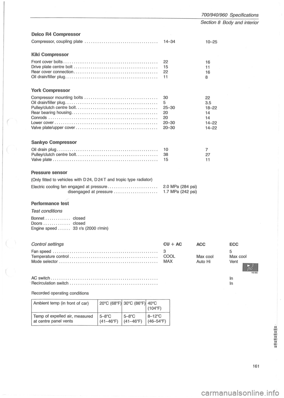
Delco R4 Compressor
Compressor, coupling plate ................................... 14-34
Kiki Compressor
Front cover bolts. . . . . . . . . . . . . . . . . . . . . . . . . . . . . . . . . . . . . . . . . . . . . 22
Drive
plate centre bolt . . . . . . . . . . . . . . . . . . . . . . . . . . . . . . . . . . . . . . . . 15
Rear cover connection. . . . . . . . . . . . . . . . . . . . . . . . . . . . . . . . . . . . . . . .
22
Oil drain/filler plug. . . . . . . . . . . . . . . . . . . . . . . . . . . . . . . . . . . . . . . . . . . . 11
York Compressor
Compressor mounting bolts ........................ .......... .
Oil drain/filler plug ........................................... .
Pulley/clutch centre bolt. ..................................... .
Rear bearing housing
.................................. ...... .
Con rods .
.................................................. .
Lower cover
........................................ .. ...... .
Valve plate/upper cover ...................................... .
Sankyo Compressor
30
5
25-30
20
20
20-30
20-30
Oil drain plug. . . . . . . . . . . . . . . . . . . . . . . . . . . . . . . . . . . . . . . . . . . . . . . . 10
Pulley/clutch
centre bolt. . . . . . . . . . . . . . . . . . . . . . . . . . . . . . . . . . . . . . . 38
Valve plate. . . . . . . . . . . . . . . . . . . . . . . . . . . . . . . . . . . . . . . . . . . . . . . . . . 15
Pressure sensor
(Only fitted to vehicles with D 24, D 24 T and tropic type radiator)
70019401960 Specifications
Section 8 Body and interior
10-25
16
11
16
8
22
3.5
18-22
14
14
14-22
14-22
7
27
11
Electric cooling fan engaged at pressure ....................... .
disengaged at pressure
.................... .
2.0 MPa (284 psi)
1 .7 MPa (242 psi)
Performance test
Test conditions
Bonnet . . . . . . . . . . .. closed
Doors . . . . . . . . . . . .. closed
Engine
speed. . . . .. 33 r/s (2000 r/min)
Control settings
Fan speed ........................... ...................... .
Temperature
control . ................................. ....... .
Mode
selector . ............................................. .
AC switch ............. ..................................... .
.
Recirculation switch ......................................... .
Recorded operating conditions
Ambient temp
(in front of car) 20°C (68°F) 30°C (86°F)
40°C
(104 °
F)
Temp of expelled air, measured 5-8°C 5-8°C 8-12°C
CU + AC
3
COOL
MAX
at centre panel vents
(41-46°F) (41-46 °F) (46-54°F)
ACC
Max cool
Auto Hi
ECC
5
Max cool
Vent
-In
In
143985
161
·11 lit ·11 lit ·11 lit ·11 III II