1982 VOLVO 700 length
[x] Cancel search: lengthPage 91 of 168
(
70019401960 Specifications
Section
2 B 280 Engine
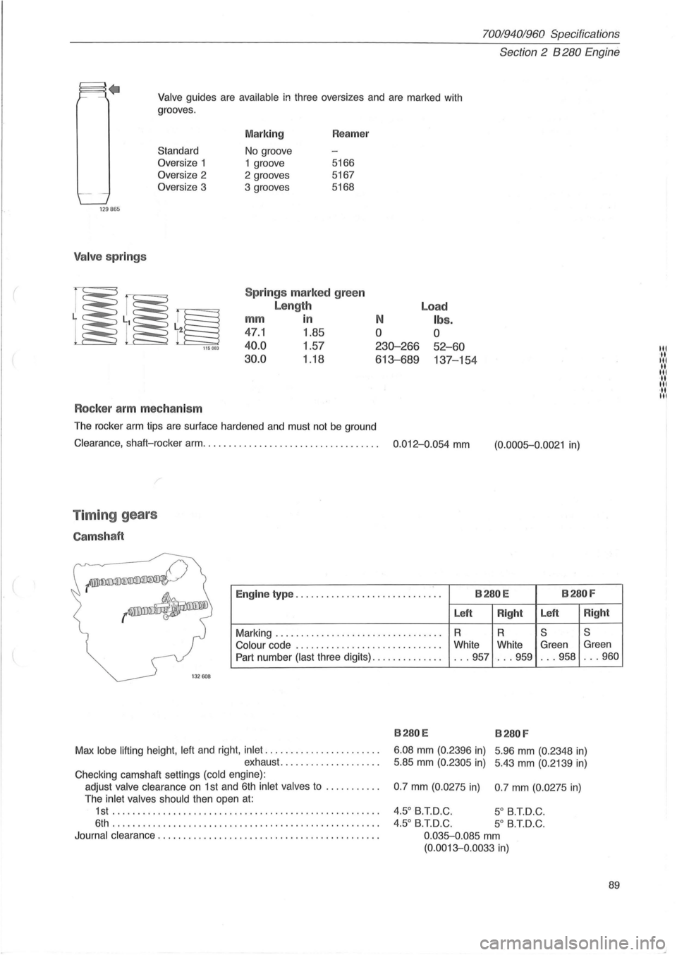
Valve guides are available in three oversizes and are marked with
grooves .
129865
Valve springs
Standard
Oversize 1
Oversize 2
Oversize 3
115083
Rocker arm mechanism
Marking
No groove
1 groove
2 grooves
3 grooves Reamer
5166
5167
5168
Spr ings marked green
Length
mm in
47.1 1.85
40.0 1.57
30.0 1.18
N
o
230-266
613-689
The rocker arm tips are surface hardened and must not be ground
Load
Ibs.
o
52-60
137-154
Clearance, shaft-rocker arm. . . . . . . . . . . . . . . . . . . . . . . . . . . . . . . . . . . 0.012-0.054 mm
Timing gears
Camshaft
(0.0005-0.0021 in)
~
--~
Engine type ............................. B280E B280F
Left
Right Left
Right
Marking
........................... ...... R R S S
Colour
code ...... ... .................... White
White Green Green
Part number (last three digits)
.............. ... 957 ... 959 . .. 958 . .. 960
1
32608
B280E B280 F
Max lobe lifting height . left and right. inlet
...................... .
exhaust
........... ' " ... .. . 6.08
mm (0.
2396 in) 5 .96 mm (0.2348 in)
5.85 mm (0.2305 in) 5.43 mm (0.2139 in)
Checking camshaft settings (cold engine) :
adjust valve clearance
on 1 st and 6th inlet valves to .......... .
The inlet valves should then open
at:
1st ...... .................... .......................... .
6th . ................................................... .
Journal clearance
............................... ............ . 0.7
mm (0.0275 in) 0.7 mm (0.
0275 in)
4.50 B.T.D.C. 5 0 B.T.D.C .
4.50 B.T.D.C. 5
0 B.T.D.C.
0 .035-0.085
mm
(0.0013-0.0033 in)
89
III .. III .. III ... III ·11 III
Page 94 of 168
70019401960 Specifications
Section 2 B 280 Engine
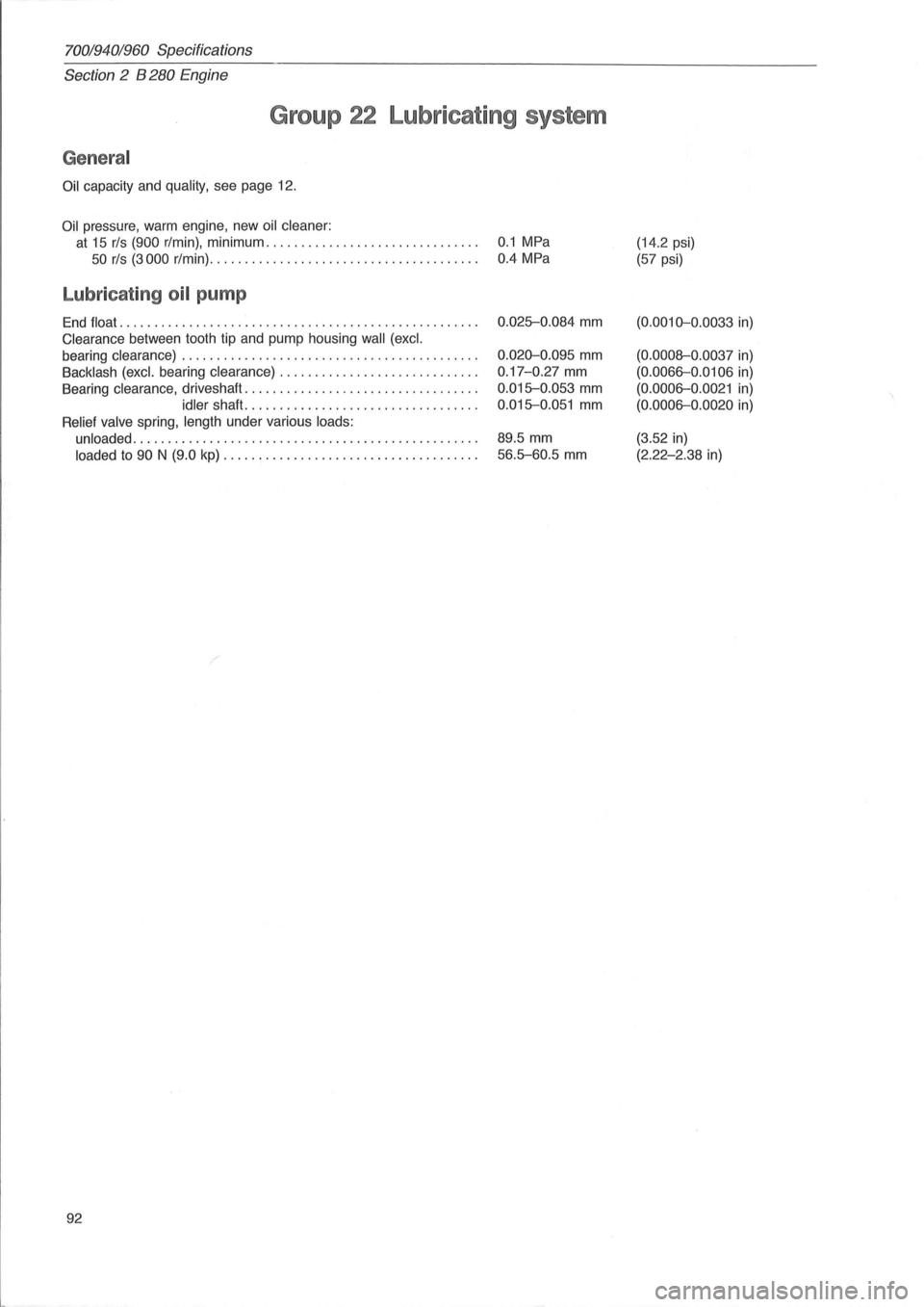
Group 22 Lubricating system
General
Oil capacity and quality, see page 12.
Oil pressure, warm engine , new oil cleaner:
at 15 rls (900 r/min), minimum. . . . . . . . . . . . . . . . . . . . . . . . . . . . . . . 0.1 MPa
50 rls (3000 r/min). . . . . . . . . . . . . . . . . . . . . . . . . . . . . . . . . . . . . . . 0.4 MPa
Lubricating oil pump
End float ...... ........................ ..................... .
Clearance between tooth tip and pump housing wall (excl.
bearing clearance) .
......................................... .
Backlash (excl. bearing clearance) ............................ .
Bearing clearance , driveshaft ....
............................. .
idler shaft ................................. .
Relief valve spring, length under various loads:
unloaded
..................... ................. ........... .
loaded to 90 N (9.0 kp) .................................... .
92
0.025-0.084 mm
0.020-0.095 mm
0.17 -0.27 mm
0.015-0.053 mm
0.015-0.051 mm
89.5 mm
56.5-60.5 mm
(14.2 psi)
(57 psi)
(0.0010-0 .0033 in)
(0.0008-0 .0037 in)
(0.0066-0 .0106 in)
(0.0006-0 .0021 in)
(0.0006-0.0020 in)
(3.52 in)
(2.22-2.38 in)
Page 101 of 168
(
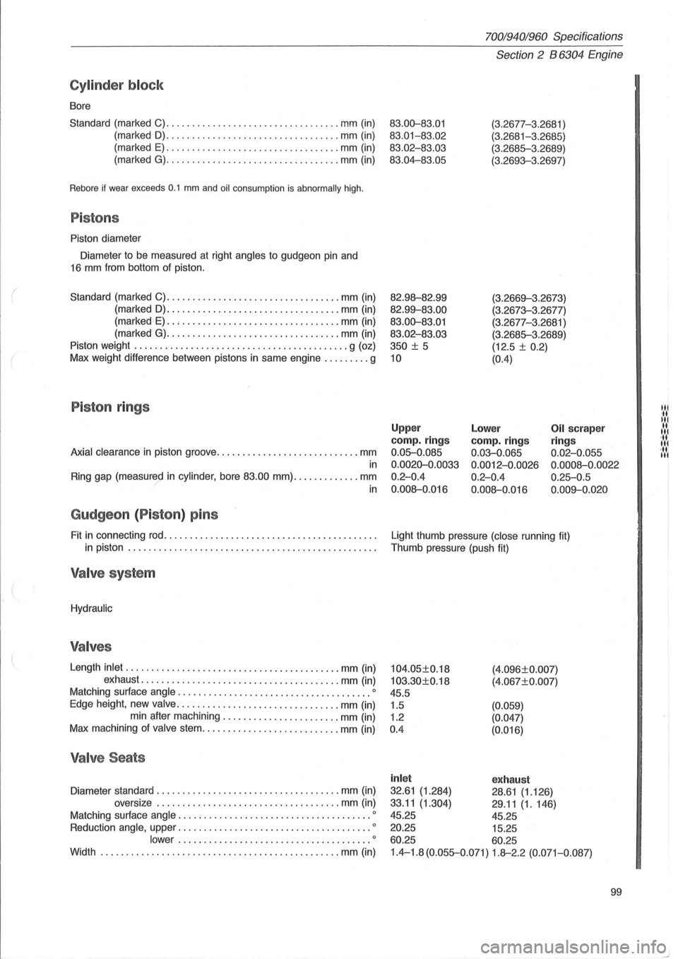
Cylinder block
Bore
Standard (marked C)
........................... ....... mm (in)
(marked
D) ........... ....................... mm (in)
(marked
E) .................................. mm (in)
(marked
G) ................... . .............. mm (in)
Rebore if wear exceeds 0.1 mm and oil consumption is abnormally high.
Pistons
Piston diameter
Diameter to be measured at right
angles to gudgeon pin and
16 mm from bottom of piston.
Standard (marked C)
.................................. mm (in)
(marked
D): ................................ . mm (in)
(marked
E) .. , ........................ ....... mm (in)
(marked
G) ............ ...................... mm (in)
Piston weight
.......................................... g (oz)
Max weight difference between pistons in same engine
......... g
Piston rings
Axial clearance in piston groove ............................ mm
in
Ring gap (measured in cylinder, bore 83.00 mm) ............. mm ? in
Gudgeon (P iston ) pins
Fit in connecting rod ......................................... .
in piston
................................................ .
Valve system
Hydraulic
Valves
Length inlet ...... .................................... mm (in)
exhaust
.............. ......................... mm (in)
Matching surface
angle .................................. .... 0
Edge height, new valve ................................ mm (in)
min after machining .
...................... mm (in)
Max machining of
valve stem ................ ........... mm (in)
Valve Seats
Diameter standard .................................... mm (in)
oversize
.... ................................ mm (in)
Matching surface
angle .......................... ............ 0
Reduction angle, upper ...................................... 0
lower ................. ....... .............. 0
Width ...................................... ... ...... mm (in)
70019401960 Specifications
Section 2 B 6304 Engine
83.00-83.01
83.01-83 .02
83.02-83.03
83.04-83.05
82.98--82.99
82.99--83.00
83.00-83.01
83.02 -83.03
350
± 5
10
(3.2677-3 .2681 )
(3.2681-3.2685)
(3.2685-3 .2689)
(3.2693-3.2697)
(3.2669--3.26 7
3)
(3.2673-3.2677)
(3.2677-3.
2681 )
(3.2685-3.2689)
(12.5 ±
0.2)
(0.4)
Upper
camp. rings
0.05-0.085
0.0020-0.0033
0.2-0.4
0.008--0.016
Lower
camp. rings
0.03-0.065
0.0012-0.0026
0.2-0.4
0.008--0.016
Oil scraper
ring s
0.02-0.055
0.0008 -0.0022
0.25-0.5
0.009--0 .020
Light thumb pressure (close running fit)
Thumb pressure (push fit)
104.05±0.18
103.30±0.18
45.5
1.5
1.2
0 .4 (4
.
096±0.007)
(4.067±0. 007)
(0.059)
(0.047)
(0.016)
inl et exhaust
32.61 (1.284) 28.61 (1.126)
33.11
(1.304) 29 .11 (1.146)
45.25 45.25
20.25 15.25
60.25 60.25
1.4-1.8 (0.055-0.071) 1.8--2.2 (0.071-0.087)
99
Itl
It
Itl
.... 1 '11 Itl ... Itl
Page 102 of 168
70019401960 Specifications
Section 2 B 6304 Engine
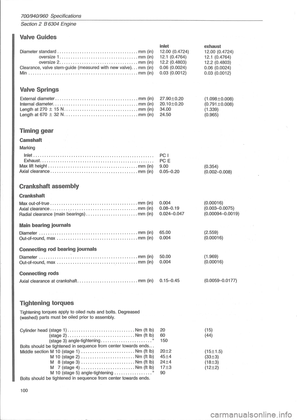
Valve Guides
Diameter standard .................................... mm (in)
oversize 1
................................... mm (in)
oversize 2
...................... ............. mm (in)
Clearance, valve stem-guide (measured with new valve) ... mm (in)
Min .
................................................ mm (in)
Valve Springs
External diameter ..................................... mm (in)
Internal diameter ...................................... mm (in)
Length at
270 ± 15 N ................................. mm (in)
Length at
670 ± 32 N ................................. mm (in)
Timing gear
Cams haft
Marking
Inlet ..................................................... .
Exhaust
.................................................. .
Max
lift height ................... ..................... mm (in)
Axial clearance ....................................... mm (in)
Crankshaft assembly
Crankshaft
Max out-ol-true ...................................... . mm (in)
Axial clearance ....................................... mm (in)
Radial clearance (main bearings) ....................... mm (in)
Main bearing journals
Diameter ............................................ mm (in)
Out-ol-round, max
.................................... mm (in)
Connecting rod bearing journ als
Diameter ................................... ......... mm (in)
Out-aI-round, max
.................................... mm (in)
Connecting rods
Axial clearance at crankshaft ........................... mm (in)
Tightening torques
Tightening torques apply to oiled nuts and bolts. Degreased
(washed) parts must
be oiled prior to assembly.
Cylinder
head (stage 1) .............................. Nm (ft Ib)
(stage 2) .............................. Nm (ft Ib)
(stage 3) angle -tightening ....................... 0
Bolts should be tightened in sequence Irom center towards ends .. .
Middle section M 10 (stage 1) ........................ Nm (ft Ib)
M 10 (stage 2) ........................ Nm (ft Ib)
M 8 (stage 3) ........................ Nm (It Ib)
M 7 (stage 4) ........................ Nm (It Ib)
M 10 (stage 5) angle -tightening ................. 0
Bolts should be tightened in sequence Irom center towards ends.
100
inlet
12.00 (0.4724)
12.1 (0.4764)
12.2 (0.4803)
0.06 (0.0024)
0.03 (0.0012)
27.90±0.20
20.10±0.20
34.00
24.50
PC I
PC E
9.00 0.05-0.20
0.004
0.08-0.19
0.024-0.047
65.00 0.004
50.00 0.004
0.15-0.45
20
60 150
20±2
45±4
24±4
17±3
90
exhaust
12.00 (0.4724)
12.1 (0.4764)
12.2 (0.4803)
0.06 (0.0024)
0.03 (0.0012)
(1.098±0.008)
(0.791 ±0.008)
(1.339)
(0.965)
(0.354)
(0.002-0.008)
(0. 00016)
(0.003-0.0075)
(0.00094-0.0019)
(2.559)
(0.00016)
(1.969)
(0.00016)
(0.0059-0 .0177)
(15)
(44)
(15±1.5)
(33±3)
(18±3)
(12±2)
Page 103 of 168
(
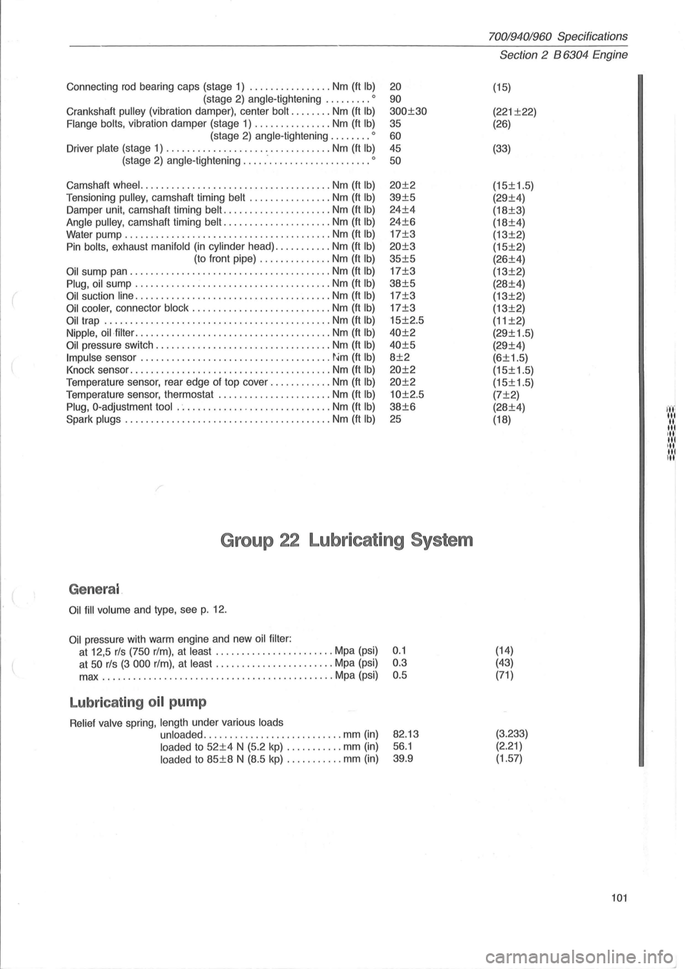
Connecting rod bearing caps (stage 1) ................ Nm (ft Ib)
(stage 2) angle-tightening ......... 0
Crankshaft pulley (vibration damper), center bolt ........ Nm (ft Ib)
Flange bolts, vibration damper (stage 1) ............... Nm (ft Ib)
(stage 2) angle-tightening ........ 0
Driver plate (stage 1) ......................... ....... Nm (ft Ib)
(stage 2) angle-tightening ......................... 0
Camshaft wheel. .................................... Nm (ft Ib)
Tensi oning pulley, camshaft timing belt ................ Nm (ft Ib)
Damper unit, camshaft timing belt ..................... Nm (ft Ib)
Angle pulley, camshaft timing belt ..................... Nm (ft Ib)
Water pump ........................................ Nm (ft Ib)
Pin bolts, exhaust manifold (in cylinder head) ........... Nm (ft Ib)
(to front pipe) .............. Nm (ft Ib)
Oil sump pan ....................................... Nm (ft Ib)
Plug, oil sump ...................................... Nm (ft Ib)
Oil suction line ...................................... Nm (ft Ib)
Oil cooler, connector block ........................... Nm (ft Ib)
Oil trap ............................................ Nm (ft Ib)
Nipple, oil·filter ...................................... Nm (ft Ib)
Oil pressure switch .................................. Nrn (ft Ib)
Impulse sensor ..................................... ~~m (ft Ib)
Knock sensor ....................................... Nm (ft Ib)
Temperature sensor, rear edge of top cover ............ Nm (ft Ib)
Temperature sensor, thermostat ............... ....... Nm (ft Ib)
Plug, O-adjustment tool .............................. Nm (ft Ib)
Spark plugs ... ..................................... Nm (ft Ib)
20
90
300±30
35
60 45
50
20±2
39±5
24±4
24±6
17±3
20±3
35±5
17±3
38±5
17±3
17±3
15±2.5
40±2
40±5
8±2
20±2
20±2
10±2.5
38±6
25
Group 22 Lubricating System
Genera l
Oil fill volume and type, see p. 12.
Oil pressure with warm engine and new oil filter :
at 12,5 rls (750 rim), at least ....... ................ Mpa (psi) 0.1
at
50 rls (3 000 rim), at least ....................... Mpa (psi) 0.3
max
...................... ....................... Mpa (psi) 0.5
Lubricat ing oil pump
Relief valve spring, length under various loads
unloaded
.................... ....... mm (in)
loaded to 52±4 N (5.2 kp) ....... .... mm (in)
loaded to 85±8 N (8.5 kp) ........... mm (in)
82.13
56.1
39.9
70019401960 Specifications
Section 2 B 6304 Engine
(15)
(221 ±22)
(26)
(33)
(15±1.5)
(29±4)
(18±3)
(18±4)
(13±2)
(15±2)
(26±4)
(13±2)
(28±4)
(13±2)
(13±2)
(11 ±2)
(29±1.5)
(29±4)
(6±1.5)
(15±1.5)
(15±1.5)
(7±2)
(28±4)
(18)
(14)
(43)
(71 )
(3.233) (2.21)
(1.57)
101
I ..... ' '.','
"' ,III III ill u,1
Page 106 of 168
70019401960 Specifications
Section
2 B 6304 Engine
I
150425
o 580 464 ...
145791
145792
Sil
104
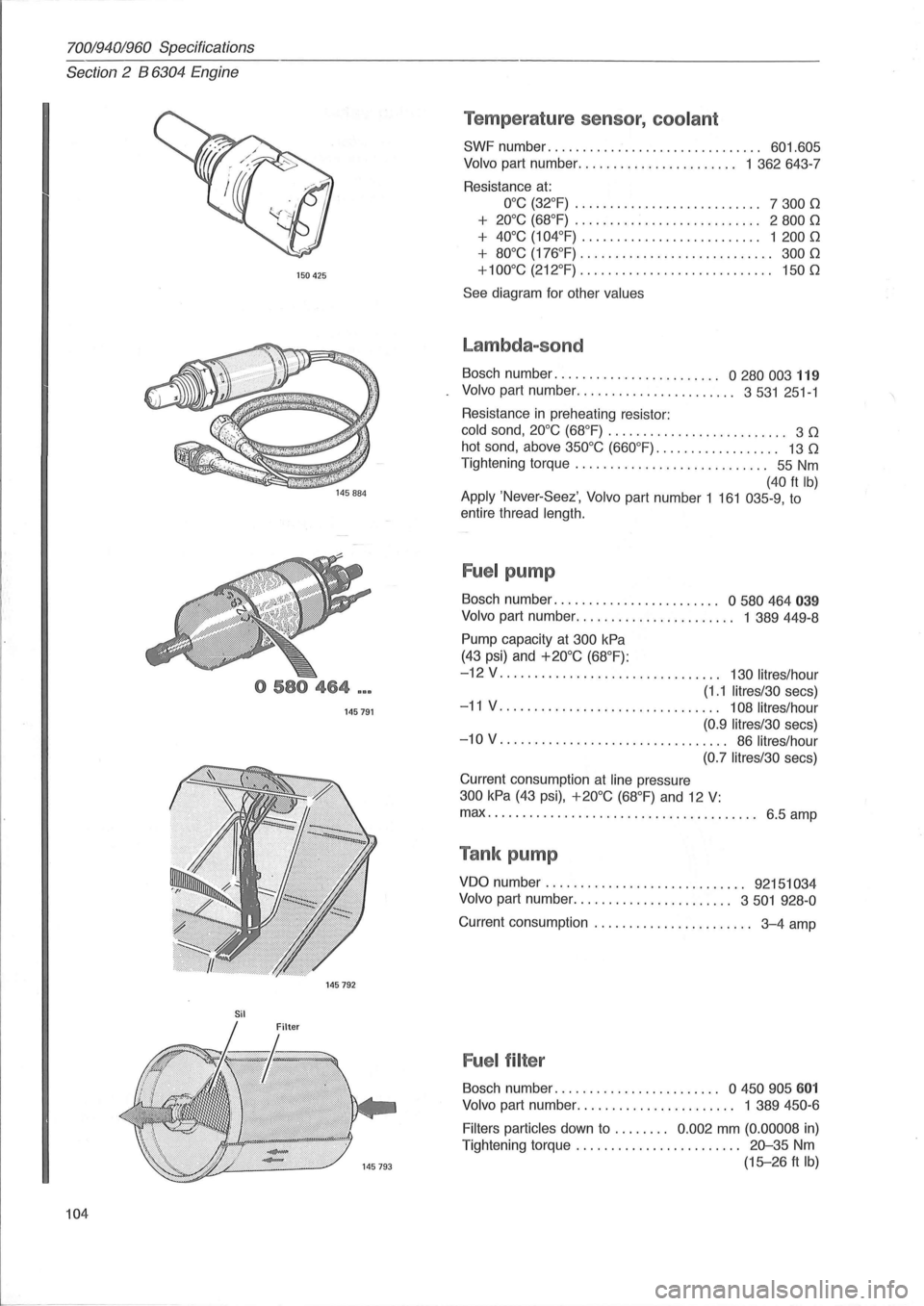
Temperature sensor, coolant
SWF number. . . . . . . . . . . . . . . . . . . . . . . . . . . . . .. 601.605
Volvo part number ....................... 1 362643-7
Resistance
at:
O°C (32°F) . . . . . . . . . . . . . . . . . . . . . . . . . .. 7 300 0
+ 20°C (68°F) . . . . . . . . . . . . . . . . . . . . . . . . . .. 2 800 0
+ 40°C (104°F) . . . .. . . .. . .. . .. . . . . . . . . . .. 1 200 0
+ 80°C (176°F) . . . . . . . . . . . . . . . . . . . .. . . . . . .. 300 0
+100°C (212°F)
............................ 1500
See diagram for other values
Lambda-sond
Bosch number. . . . . . . . . . . . . . . . . . . . . . .. 0 280 003 119
Volvo part number ....................... 3531 251-1
Resistance
in preheating resistor:
cold sand, 20°C (68°F) . . . . . . . . . . . . . . . . . . . . . . . . .. 3 0
hot sand, above 350°C (660°F). . . . . . . . . . . . . . . . .. 13 0
Tightening torque . . . . . . . . . . . . . . . . . . . . . . . . . . .. 55 Nm
(40 ft Ib) Apply 'Never-Seez', Volvo part number 1 161 035-9, to
entire thread
length.
Fuel pump
Bosch number. . . . . . . . . . . . . . . . . . . . . . .. 0 580 464 039
Volvo part number. . . . . . . . . . . . . . . . . . . . . .. 1 389449-8
Pump capacity at 300 kPa
(43 psi) and +20°C (68°F):
-12 V . . . . . . . . . . . . . . . . . . . . . . . . . . . . . . .. 130 lit res/hour
(1.1 litres/30 secs)
-11 V. . . . . . . . . . . . . . . . . . . . . . . . . . . . . . .. 108 litres/hour
(0.9 Iitres/30
secs)
-10 V. . . . . . . . . . . . . . . . . . . . . . . . . . . . . . . .. 86 litres/hour
(0.7 litres/30
secs)
Current consumption
at line pressure
300 kPa (43 psi), +20°C (68°F) and 12 V:
max ................................ ....... 6.5 amp
Tank pump
VDO number. . . . . . . . . . . . . . . . . . . . . . . . . . . .. 92151034
Volvo
part number ....................... 3501 928-0
Current consumption . . . . . . . . . . . . . . . . . . . . . .. 3-4 amp
Fuel filter
Bosch number. . . . . . . . . . . . . . . . . . . . . . .. a 450 905 601
Volvo part number. . . . . . . . . . . . . . . . . . . . . .. 1 389 450-6
Filters particles
down to . . . . . . .. 0.002 mm (0.00008 in)
Tightening torque . . . . . . . . . . . . . . . . . . . . . .
.. 20-35 Nm
(15-26 ft Ib)
Page 113 of 168
(
70019401960 Specifications
Section 2
024, 024 T, 024 TIC Engines
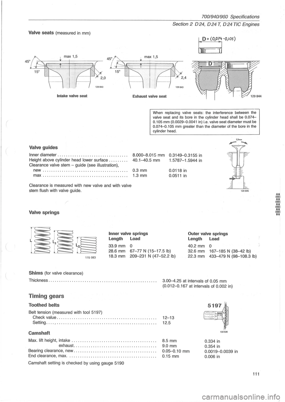
Valve seats (measured in mm)
I!+ (O'O~rIOS)
I max 1,5
129843
Intak e valve sea t
Exhaust valv e seat
When
replacing valve seats: the interference between the valve seat and its bore in the cylinder head shall be 0.074-
0.105 mm (0.0029-0 .0041 in) i.e. valve seat diameter must be 0.074-0.105 mm greater than the diameter of the bore in the cylinder head .
Valve guides
Inner diameter ............... ................. .
Height above cylinder head
lower sur1ace ........ .
8.000-8.015 mm 0 .3149-0.3155 in
40.1-40.5 mm 1 .5787-1.5944 in Clearance valve stem -guide (see illustration),
new........................................ 0.3 mm
max.. ...................................... 1.3 mm
Clearance is measured with new valve and with valve
stem flush with valve guide.
/
Valve springs
Inner va lv e spring s
Length Load
33.9 mm 0 0.0118
in
0.0511 in
Outer
valve springs
Length Load
40.2 mm 0
1,3mm '-.~
115083
28.6 mm 67-77 N (15-17 .5 Ib)
18.3 mm 209-231 N (47-52.2 Ib)
32.6 mm 167-185 N (38-42 Ib)
22.3 mm 433-479N (98-108.3 Ib)
S him s (for valve clearance)
Thickness. . . . . . . . . . . . . . . . . . . . . . . . . . . . . . . . . . . . . . . . . . . . . . . . . . .
3.00-4.25 at intervals of 0.05 mm
(0.012-0 .167 at intervals of 0 .002 in)
Timing gears
Toothed belts
Belt tension (measured with tool 5197)
Check
value. . . . . . . . . . . . . . . . . . . . . . . . . . . . . . . . . . . . . . . . . . . . . . . 12-13
Setting
... . , . . . . . . . . . . . . . . . . . . . . . . . . . . . . . . . . . . . . . . . . . . . . . . . 12.5
Camshaft
Max. lift height , intake ....................................... .
exhaust
...................................... .
Bearing clearance, new .
..................................... .
End clearance , max. . ....................................... .
Camshaft setting
is checked by using gauge 5190
8.5 mm
9.0 mm
0.05-0.10 mm
0 .15 mm
133536
0.334 in
0.354 in
0.0019-0.0039 in
0.006 in
111
·111 1111 ·111 1111 ·111 1111 11 .... 1 III
Page 116 of 168
70019401960 Specifications
Section 2 024, 024 T, 024 TIC Engines
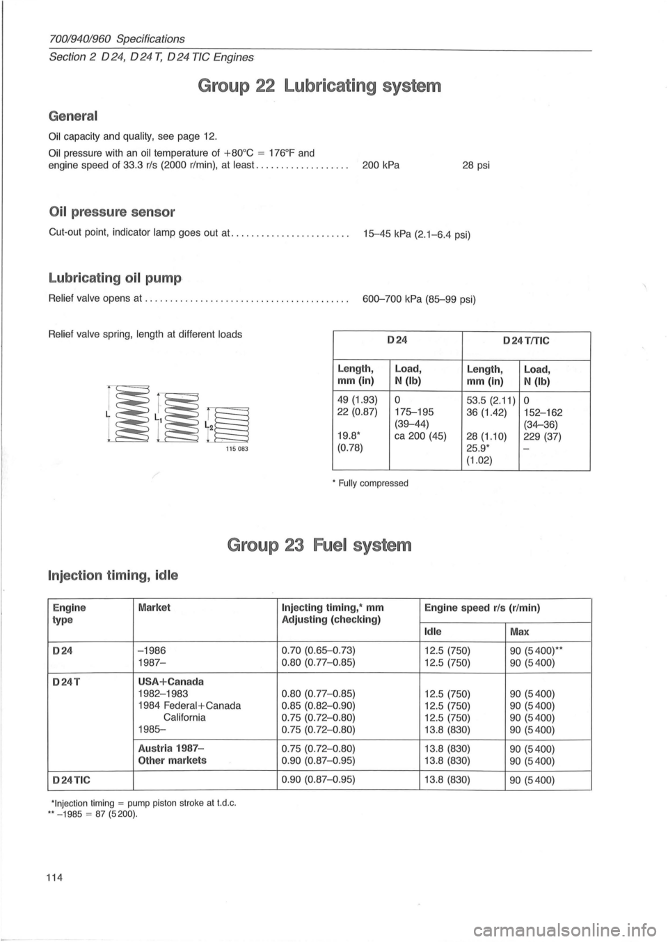
Group 22 Lubricating system
General
Oil capacity and quality, see page 12.
Oil pressure with an oil temperature of +80°C = 176°F and
engine speed of 33.3 rls (2000 r/min) , at least. . . . . . . . . . . . . . . . . . . 200 kPa 28 psi
Oil pressure sensor
Cut-out point, indicator lamp goes out at. ...................... . 15-45 kPa (2.1-6.4 psi)
Lubricating oil pump ,
Relief valve opens at ........................................ . 600-700 kPa (85-99 psi)
Relief valve spring, length at different loads 024 o 24TfTlC
Length, Load,
Length, Load,
mm (in) N (Ib) mm (in) N (Ib)
49 (1.93) 0 53.5 (2.11) 0 22 (0.87)
175-195
36 (1.42) 152-162
(39-44) (34-36)
19.8 * ca 200 (45)
28(1.10) 229 (37)
115 083 (0.78) 25.9 * -
(1.02)
* Fully compressed
Group 23 Fuel system
Injection timing, idle
Engin e Market
type
024 -1986
1987-
024T USA+Can ada
1982-1983
1984
Federal + Canada
California
1985-
Austr ia 1987 -
Other markets
024TIC
*Injection timing = pump piston stroke at t.d .c . ** - 1985 = 87 (5200).
114
Injecting timing, * mm
Engine speed rls (r/min)
Adjusting (check ing)
Idle Max
0.70 (0.65-0 .73)
12.5 (750) 90 (5400)* *
0.80 (0.77-0.85) 12.5 (750) 90 (5400)
0.80
(0.77-0 .85) 12.5 (750) 90 (5400)
0.85 (0.82-0 .90) 12.5 (750) 90 (5400)
0.75 (0.72- 0 .80) 12.5 (750) 90 (5400)
0.75 (0.72-0 .80) 13.8 (830) 90 (5400)
0.75 (0.72-0.80) 13.8 (830) 90 (5400)
0 .90
(0.87-0 .95) 13.8 (830) 90 (5400)
0.90
(0.87-0.95) 13. 8 (830) 90 (5400)