1982 VOLVO 700 check engine
[x] Cancel search: check enginePage 91 of 168
(
70019401960 Specifications
Section
2 B 280 Engine
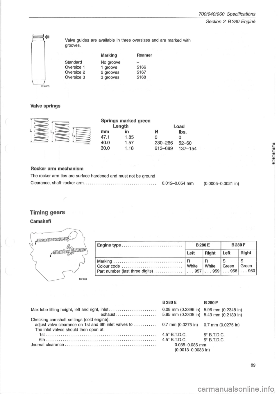
Valve guides are available in three oversizes and are marked with
grooves .
129865
Valve springs
Standard
Oversize 1
Oversize 2
Oversize 3
115083
Rocker arm mechanism
Marking
No groove
1 groove
2 grooves
3 grooves Reamer
5166
5167
5168
Spr ings marked green
Length
mm in
47.1 1.85
40.0 1.57
30.0 1.18
N
o
230-266
613-689
The rocker arm tips are surface hardened and must not be ground
Load
Ibs.
o
52-60
137-154
Clearance, shaft-rocker arm. . . . . . . . . . . . . . . . . . . . . . . . . . . . . . . . . . . 0.012-0.054 mm
Timing gears
Camshaft
(0.0005-0.0021 in)
~
--~
Engine type ............................. B280E B280F
Left
Right Left
Right
Marking
........................... ...... R R S S
Colour
code ...... ... .................... White
White Green Green
Part number (last three digits)
.............. ... 957 ... 959 . .. 958 . .. 960
1
32608
B280E B280 F
Max lobe lifting height . left and right. inlet
...................... .
exhaust
........... ' " ... .. . 6.08
mm (0.
2396 in) 5 .96 mm (0.2348 in)
5.85 mm (0.2305 in) 5.43 mm (0.2139 in)
Checking camshaft settings (cold engine) :
adjust valve clearance
on 1 st and 6th inlet valves to .......... .
The inlet valves should then open
at:
1st ...... .................... .......................... .
6th . ................................................... .
Journal clearance
............................... ............ . 0.7
mm (0.0275 in) 0.7 mm (0.
0275 in)
4.50 B.T.D.C. 5 0 B.T.D.C .
4.50 B.T.D.C. 5
0 B.T.D.C.
0 .035-0.085
mm
(0.0013-0.0033 in)
89
III .. III .. III ... III ·11 III
Page 92 of 168
70019401960 Specifications
Section
2 B 280 Engine
Crank mechanism
Cranks haft
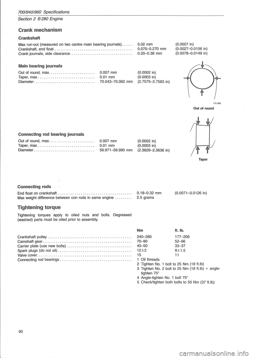
Max run-out (measured on two centre main bearing journals) ..... .
Crankshaft, end
float ........................................ .
Crank
journals, side clearance ................................ .
Main bearing journal s
Out of round, max. ; ..................... .
Taper, max
............................. .
Diameter
............................... .
Connecting rod bearing journal s
Out of round, max ....................... .
Taper,
max " ............................. .
Diameter
............................ ... .
Connecting rods
0.007 mm
0.01 mm
70.043-70.062 mm
0.007 mm
0.01 mm
59.971-59.990 mm
End float on crankshaft ...................................... .
Max weight difference between can rods
in same engine ........ .
Tightening torque
Tightening torques apply to oiled nuts and bolts. Degreased
(washed) parts must
be oiled prior to assembly.
Crankshaft pulley ........................ ................... .
Camshaft gear
.............................................. .
Carrier
plate (use new bolts) ................................. .
Spark
plugs (do not oil) .. .................................... .
Valve cover ........................................... ...... .
Connecting
rod bearings ..................................... .
90 0.02
mm
0.070-0.270 mm
0.20-0.38 mm
(0.0002 in)
(0.0003
in)
(2.7575-2.7583
in)
(0.0007 in)
(0. 0027-0.0106 in)
(0.0078--0.0149
in)
115089
Out of round
(0.0002 in)
(0.0003 in)
(2.3629--2.3636 in)
0.18--0.32
mm
2.5 grams
Nm
240-280
70-90
45-50
12±2
15
1 Oil threads
Taper
(0.0071-0.0126 in)
ft. lb.
177-206
52-66
33-37
9±1.5
11
2 Tighten No.1 bolt to 25 Nm (18 ft.lb)
3 Tighten
No.2 bolt to 25 Nm (18 ft.lb) + angle
tighten 75°
4 Angle -tighten No. 1 bolt 75°
5 Check/tighten both bolts to 50 Nm (37 ft.lb)
Page 95 of 168
(
70019401960 Specifications
Section
2 8280 E ngine
Group 23 Fuel system
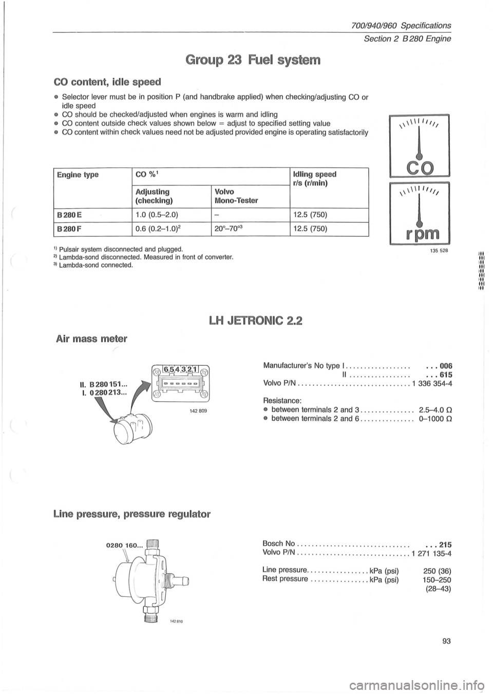
CO content , id le speed
• Selector lever must be in position P (and handbrake applied) when checking/adjusting CO or
idle speed
• CO should be checked/adjusted when engines is warm and idling
• CO content outside check values shown below = adjust to specified setting value
• CO content within check values need not be adjusted provided engine is operating satisfactorily
E ng
ine ty pe CO %1 Id lin g speed
r/s (r/min)
Adjustin g V
o lv o
( c h ec kin g) Mo
no-Teste r
B280E 1.0 (0.5-2 .0) -12.5 (750)
B280F 0.6 (0.2 - 1.0j2 20°_70°3 12.5 (750)
\\\\1""
rpm
1) Pulsair system disconnected and plugged. 135 528 2 ) Lambda -sond disconnected . Measured in front of converter . 3) Lambda-sand connected.
LH JETRONIC 2.2
Air mass meter
Line pressure , pressure
regu lator
Manufacturer's No type I . . . . . . . . . . . . . . . . . . . .. 00 6
II ................. . . . 615
Volvo
PIN ... ............................ 1 336 354-4
Resistance:
• between terminals 2 and 3. . . . . . . . . . . . . .. 2 .5-4.0 0
•
between terminals 2 and 6 . . . . . . . . . . . . . .. 0-1000 0
Bosch No . . . . . . . . . . . . . . . . . . . . . . . . . . . . . . . . .. 215
Volvo
PIN . ......................... ..... 1 271 135 -4
Line pressure ................. kPa (psi)
Rest pressure
................ kPa (psi) 250 (36)
150-250
(28-43)
93
'" III ill III ,II
,'N III 'II
Page 104 of 168
70019401960 Specifications ./ " ' "."--Section 2 B 6304 Engine
Group 23 Fuel System
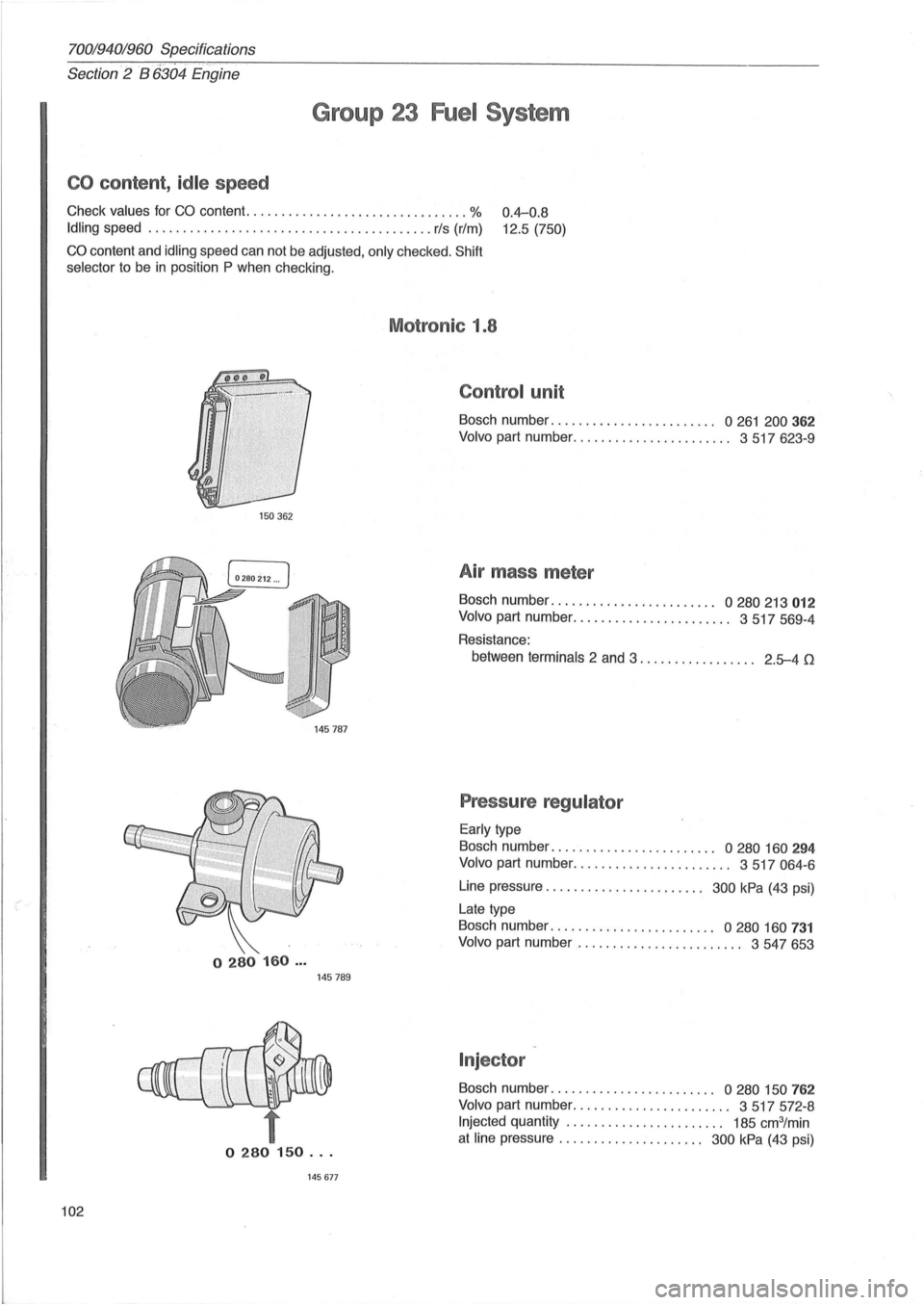
CO content , idle speed
Check values for CO content. ............................... % 0.4-0.8
12.5 (750) Idling speed ............................ ......... .... rls (rim)
CO content and idling speed can not be adjusted , only checked. Shift
selector
to be in position P when checking.
150362
o 280 160 ... 145 789
t o 280 150 ...
145677
102
Motronic 1.8
Control unit
Bosch number ....................... . 0261 200362
Volvo part number. . . . . . . . . . . . . . . . . . . . . . . 3 517 623-9
Air mass meter
Bosch number ...................... " 0 280 213 012
Volvo part number ....................... 3517569-4
Resistance:
between
terminals 2 and 3. . . . . . . . . . . . . . . .. 2.5-4 0
Pressure regulator
Early type
Bosch number . . . . . . . . . . . . . . . . . . . . . .
.. 0 280 160 294
Volvo part number. . . . . . . . . . . . . . . . . . . . . .. 3 517 064-6
Line pressure ..................... " 300 kPa (4 3 psi)
Late type
Bosch number . . . . . . . . . . . . . . . . . . . . . . ..
0 280 160 731
Volvo part number ..................... .. . 3547653
Injector
Bosch number . . . . . . . . . . . . . . . . . . . . . . .. 0 280 150 762
Volvo part number ....................... 3517572-8
Injected quantity . . . . . . . . . . . . . . . . . . . . . .. 185 cm3/min
at line pressure .................. ... 300 kPa (43 psi)
Page 112 of 168
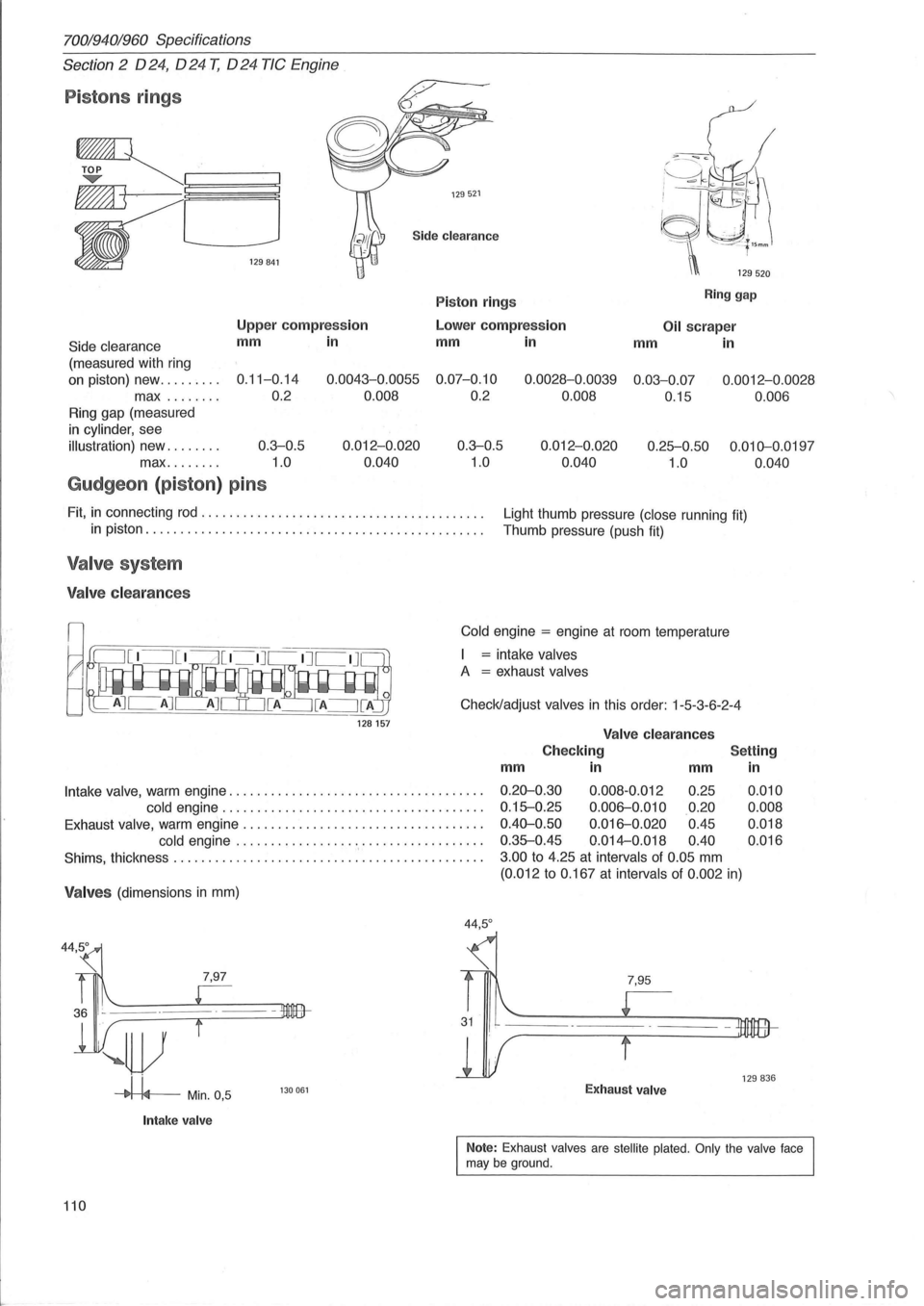
70019401960 Specifications
Section
2 024, 024 T, 024 TIC Engine
Pistons rings
~~ ~L---,-C--., -L-J
• ""~,
129521
Side cleara n ce
P iston rings R in g gap
Side clearanc e
(measured with ring
Uppe r comp ress ion
mm in Lo
wer comp ress io n O il sc rape r
mm in
mm
in
on piston) new ........ .
max
....... .
0.11-0 .14
0 .2 0
.0043 -0.0055 0.07-0.10
0.008 0.2 0.0028-0
.0039 0.03-0.0 7
0.008 0.
15
0.0012-0 .0028
0 .006
Ring gap (measured
in cylinder, see
illustration) new. . . . . . . . 0 .3-0.5
max........ 1.0 0.012
-0.020
0 .040 0.3-0.5
1.0 0.012
-0.020
0.040 0.25-0
.50
1.0 0
.010-0.0197
0.040
Gudgeon (piston ) pins
Fit, in connecting rod ........................................ .
Ligh t thumb pressure (close running fit)
T humb pressure (push
fit) in piston .............................. ............. ..... .
Valv e system
Valve clea ra nces
128157
Cold engine = engine at room temperature
= intake valves
A = exhaust valves
Check/adjust valves in this order : 1-5 -3 -6-2- 4
Va lv e cleara n ces
C heck ing
Settin g
m m in
mm
Intake valve, warm engine ..... ............................... . 0 .20-0.30 0.008 -0.012
0.25
cold
engine ................ ..................... . 0.15-0 .25 0.006-0 .010 0.2 0
E xhaust valve, warm engine ............. ..................... . 0.40-0 .50 0.016-0.020 0.45
cold
engine ................ . " ................. . 0 .35-0.45 0.014-0.018
0.40
Shims, thickness . . . . . . . . . . . . . . . . . . . . . . . . . . . . . . . . . . . . . . . . . . . .. 3.00 to 4.25 at intervals of 0.05 mm
(0.012 to 0.16 7 at intervals of 0.002 in)
Valves (dimensions in mm)
7,97
~r-i4--Min. 0 ,5
Int ake va lv e
130061
44 ,5 °
7,95
Exh au st valve
in
0 .010
0 .008
0 .018
0.016
129836
Note : Exhaust valves are stellite plated. Only the valve face may be ground.
110
Page 113 of 168
(
70019401960 Specifications
Section 2
024, 024 T, 024 TIC Engines
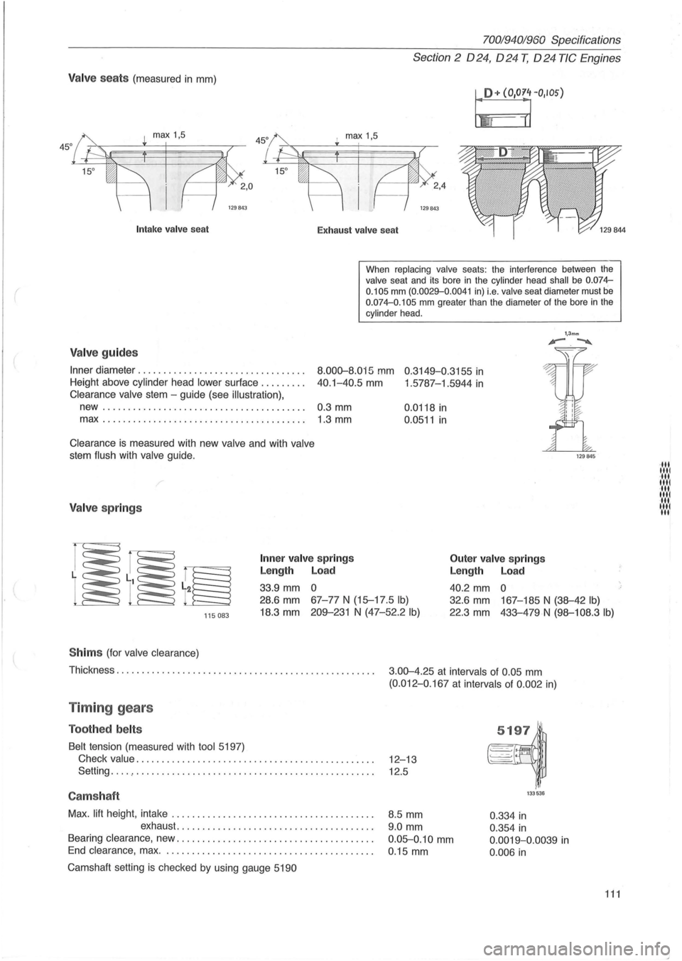
Valve seats (measured in mm)
I!+ (O'O~rIOS)
I max 1,5
129843
Intak e valve sea t
Exhaust valv e seat
When
replacing valve seats: the interference between the valve seat and its bore in the cylinder head shall be 0.074-
0.105 mm (0.0029-0 .0041 in) i.e. valve seat diameter must be 0.074-0.105 mm greater than the diameter of the bore in the cylinder head .
Valve guides
Inner diameter ............... ................. .
Height above cylinder head
lower sur1ace ........ .
8.000-8.015 mm 0 .3149-0.3155 in
40.1-40.5 mm 1 .5787-1.5944 in Clearance valve stem -guide (see illustration),
new........................................ 0.3 mm
max.. ...................................... 1.3 mm
Clearance is measured with new valve and with valve
stem flush with valve guide.
/
Valve springs
Inner va lv e spring s
Length Load
33.9 mm 0 0.0118
in
0.0511 in
Outer
valve springs
Length Load
40.2 mm 0
1,3mm '-.~
115083
28.6 mm 67-77 N (15-17 .5 Ib)
18.3 mm 209-231 N (47-52.2 Ib)
32.6 mm 167-185 N (38-42 Ib)
22.3 mm 433-479N (98-108.3 Ib)
S him s (for valve clearance)
Thickness. . . . . . . . . . . . . . . . . . . . . . . . . . . . . . . . . . . . . . . . . . . . . . . . . . .
3.00-4.25 at intervals of 0.05 mm
(0.012-0 .167 at intervals of 0 .002 in)
Timing gears
Toothed belts
Belt tension (measured with tool 5197)
Check
value. . . . . . . . . . . . . . . . . . . . . . . . . . . . . . . . . . . . . . . . . . . . . . . 12-13
Setting
... . , . . . . . . . . . . . . . . . . . . . . . . . . . . . . . . . . . . . . . . . . . . . . . . . 12.5
Camshaft
Max. lift height , intake ....................................... .
exhaust
...................................... .
Bearing clearance, new .
..................................... .
End clearance , max. . ....................................... .
Camshaft setting
is checked by using gauge 5190
8.5 mm
9.0 mm
0.05-0.10 mm
0 .15 mm
133536
0.334 in
0.354 in
0.0019-0.0039 in
0.006 in
111
·111 1111 ·111 1111 ·111 1111 11 .... 1 III
Page 116 of 168
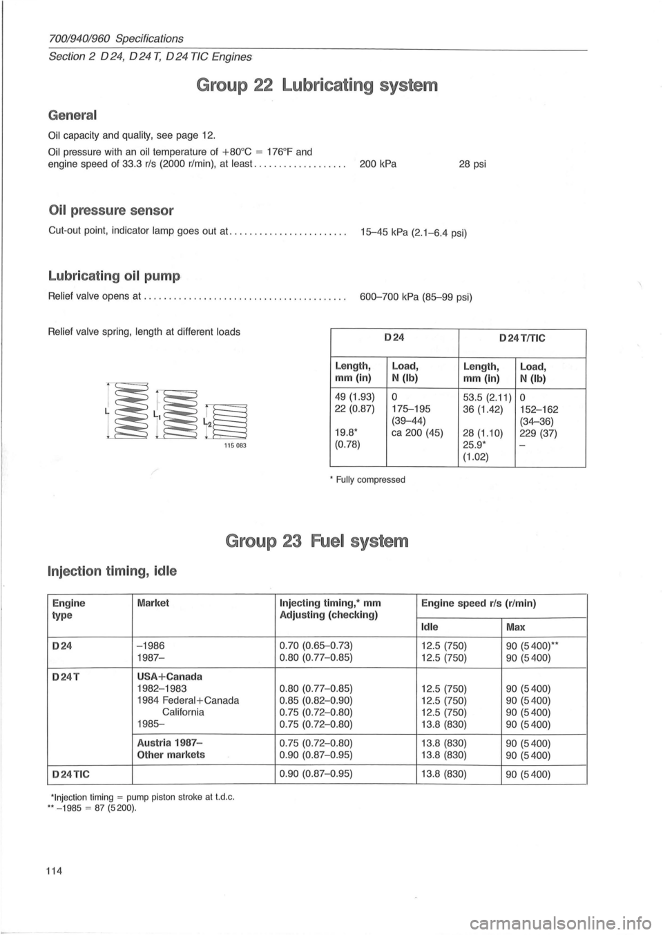
70019401960 Specifications
Section 2 024, 024 T, 024 TIC Engines
Group 22 Lubricating system
General
Oil capacity and quality, see page 12.
Oil pressure with an oil temperature of +80°C = 176°F and
engine speed of 33.3 rls (2000 r/min) , at least. . . . . . . . . . . . . . . . . . . 200 kPa 28 psi
Oil pressure sensor
Cut-out point, indicator lamp goes out at. ...................... . 15-45 kPa (2.1-6.4 psi)
Lubricating oil pump ,
Relief valve opens at ........................................ . 600-700 kPa (85-99 psi)
Relief valve spring, length at different loads 024 o 24TfTlC
Length, Load,
Length, Load,
mm (in) N (Ib) mm (in) N (Ib)
49 (1.93) 0 53.5 (2.11) 0 22 (0.87)
175-195
36 (1.42) 152-162
(39-44) (34-36)
19.8 * ca 200 (45)
28(1.10) 229 (37)
115 083 (0.78) 25.9 * -
(1.02)
* Fully compressed
Group 23 Fuel system
Injection timing, idle
Engin e Market
type
024 -1986
1987-
024T USA+Can ada
1982-1983
1984
Federal + Canada
California
1985-
Austr ia 1987 -
Other markets
024TIC
*Injection timing = pump piston stroke at t.d .c . ** - 1985 = 87 (5200).
114
Injecting timing, * mm
Engine speed rls (r/min)
Adjusting (check ing)
Idle Max
0.70 (0.65-0 .73)
12.5 (750) 90 (5400)* *
0.80 (0.77-0.85) 12.5 (750) 90 (5400)
0.80
(0.77-0 .85) 12.5 (750) 90 (5400)
0.85 (0.82-0 .90) 12.5 (750) 90 (5400)
0.75 (0.72- 0 .80) 12.5 (750) 90 (5400)
0.75 (0.72-0 .80) 13.8 (830) 90 (5400)
0.75 (0.72-0.80) 13.8 (830) 90 (5400)
0 .90
(0.87-0 .95) 13.8 (830) 90 (5400)
0.90
(0.87-0.95) 13. 8 (830) 90 (5400)
Page 117 of 168
(
l
70019401960 Specifications
Section
2 024, 024 T, 024 TIC Engines
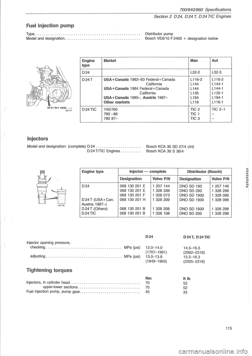
Fuel inject ion pump
Type ....................................................... . Distributor pump
Model and designation ....................................... .
Bosch VE6/10 F 2400 + designation below
VE 6/10 F 2400 ••. -. 136777
Injectors
I
Eng ine
type
024
o24T
o24TIC
Market
U
SA+Canada 1982-83 Federal+Canada
California
U
SA+Canada 1984 Federal+Canada
California
USA+Canada 1985-, Austria 1987-
Other markets
7401760
780 -86
78087-
Man
L32-2
L
116~3
L144
L144
L135
L194
L116
i 1'IC 2 : ' TIC 1
TIC 3
Model
and designation: (complete) 024 . . . . . . . . . . . . . . . . . . . . . . . . Bosch KCA 30 SO 27/4 (44)
024 TITIC Engines . . . . . . . . . . . Bosch KCA 30 S 36/4
Aut
L32-3
L 116-2
L 144 -1
L144-1
L
135-1
L194- 1
L116-1
TIC 2-1
-
-
Eng ine typ e Injector -.complete Distributor (Bosc h)
Designation
024 068130201 E
068130201 E
068130201 F
024 T (USA+Can . 068130201 H
136778 Austria 1987-)
024 T (Others) 068130201 B
o24TIC 068130201 B
Injector opening pressure,
checking. . . . . . . . . . . . . . . . . . . . . . . . . . . . . . . . . . . . . .
.. MPa (psi)
adjusting. . . . . . . . . . . . . . . . . . . . . . . . . . . . . . . . . . . . . . .. MPa (psi)
Tightening torques
Volvo PIN
1 257144
1 328336
1 328073
1 328209
1 328208
1 328 108
024
12.0-14.0
(1707-1991)
13.0-13.8
(1849-1963)
Nm
Injectors, in cylinder head. . . . . . . . . . . . . . . . . . . . . . . . . . . . . . . . . . . . . 70
upper-lower sections. . . . . . . . . . . . . . . . . . . . . . . . . . . . . . . . . 70
Fuel injection pump, pump gear. . . . . . . . . . . . . . . . . . . . . . . . . . . . . . . . 45
Designation
oNO SO 193
oNO SO 293
oNO SO 1930
oNO
SO 1930
oNO
SO 1930
oNO SO 293
024 T, 024 TIC
14.5-16 .3
(2062-2318)
15.5-16.3
(2205-2318)
ftlb
52
52
33
Volvo PIN
1 ,257146
1
328298
1 328096
1 328096
1 328298
1
328298
115