1982 Citroen CX diagram
[x] Cancel search: diagramPage 353 of 394

Downloaded from www.Manualslib.com manuals search engine OPERATION N9 MA. 530.0 : Cbcc-king thv c)lcctrical com&r~cr~ts Op. MA. 530.0 1
I. CHECKING THE OUTPUT OF THE ALTERNATORS
7
co
co
5 or, better still, using a combined
z Connect up as per diagram; using
voltmeter V, ammeter A and rheostat,
,iiJ (( voItmeter/ammeter/rheostat~~.
2
-
2 In order to measure the output of the alternator, progressively increase the engine speed, and actuate the rheostat
5 to maintain the voltage at 14 V.
E
-c
9
*
1. 12 V 80 Amp alternator : PARIS-RHONE : A 14 R 11
Cut-in speed under voltage of 14 V : 1100 rpm ( alternator speed )
Output, under voltage of 14 V :
40 Amps at 1500 rpm ( alternator j. 690 rpm ( engine )
69 Amps at 3000 rpm ( alternator ), 1375 rpm ( engine )
78 Amps at 6000 rpm ( alternator ). 2750 rpm ( engine )
80 Amps at 8000 rpm ( alternator ‘), 3670 rpm ( engine )
F 2. 12 V 53 Amp alternator : DUCELLIER 7584 and MOTOROLA 510-2 Cut-in speed under voltage of 14 V : 1100 rpm ( alternator speed)
Output, under voltage of 14 V
z.21 Amps at 1480 rpm ( alternator 1 680 rpm ( engine )
46 Amps at 3300 rpm ( alternator ): 1510 rpm ( engine )
51 Amps at 6000 rpk ( alternator ) 2750 rpm (engine )
53 Amps at 8000 rpm ( alternator ). 3670 rpm ( engine )
3. 12 V 72 Amp alternator : PARIS-RHONE A 14 R 3, and MOTOROLA 510-4
Cut-in speed under voltage of 14 V : 1100 rpm ( alternator speed)
Output, under voltage of 14 V : 33
Amps at 1480 rpm ( alternator ). 680 rpm ( engine )
62 Amps at 3300 rpm ( alternator 1 1510 rpm ( engine )
70 Amps at 6000 rpm
( alternator ) 2750 rpm ( engine )
72 Amps at 8000 rpm ( alternator 1. 3670 rpm ( engine )
If these figures are not obtained, check alternator belt, and its tension. If these are correct, recondition alternator
Page 354 of 394

Downloaded from www.Manualslib.com manuals search engine Il. CHECKING THE REGULATED TENSION OF THE REGULATORS
CHARACTERISTICS
- Two-stage voltage regulator : Ref : DUCELLIER 8379 A, PARIS-RHONE AYC 2114 and AYC 2117.
SEV-MARCHAL F. 14 V 72717102
These voltage regulators determine the intensity of the current in the alternator inductor in order to maintain a
constant regulated voltage at the battery terminals.
, CHECKING THE REGULATED VOLTAGE
(.‘hcckitlg ti7c rc~~~~~l~tc~cl u~IIcl,~c~ mris t 170 rnrric,rl out u,ith a lrilly darg~~rl hnttcry.
Connect up as per diagram below, using a voltmeter V, an ammeter A and a rheostat, or better still, using a
combined
o voltmeter/ammeter/ rheostat )).
Start engine, and let it idle.
Switch off the ignition, and immediately switch it back on in
order to demagnetize the voltage regulator.
Accelerate the engine so as to reach the adjustment speed for the alternator. Actuate the rheostat, smoothly
without turning it back, in order to increase the current supplied by the alternator, and read the corresponding
voltage.
Take several measurements of regulated tension, and check that the values obtained are between 13 and 14.2 volts,
taking into account the correction value due to the temperature. If the readings are not correct, replace voltage
regulator.
Exe Voltage regulators : DUCELLIER 8379 A
PARIS-RHONE ;;E ;;;; -
SEV-MARCHAL F.14 V72717102
- Adjustment speed : 6000 rpm (alternator)
2750 rpm (engine)
- R egulated voltage adjustment :
between 13 and 14.2 V
Page 359 of 394

Downloaded from www.Manualslib.com manuals search engine OPERATION No MA. 560.0 : ~hrrkin~ o,,d oc/@s/i,,g I/><, wiurisrrrr,, wip’r. Op. MA. 560.0
1
Fi
m
0 CHECKING AND ADJUSTING THE WINDSCREEN WIPER.
FRONT WINDSCREEN WIPER MOTOR
CHARACTERISTICS.
Manufacturer DUCELLIER
Reference No. 4966 A
Field coils Ferrite
Armature : Endfloot (adjustable by means of stop-screw) : 0.2 mm
Nominal dia. of commutator :
24 mm
Min. dia. after machining : 23 mm
Brushes : Ref. No. :
CL 7239
Minimum length after wear : 5.5 mm
Ratio : .._...................................................................................................
44 1
Connection and circuit diagram as in Op. MA. 510 00.
ELECTRICAL CHECK. BOSCH
0390 346 127
Ferrite
0
23.2 mm
23 mm
1.394.320-058 059, 062
7.5 mm
49 1
1. First speed :
Nominal power : IO watts
Speed, under no load, at 13.5 volts = 50 rpm Corresponding current = I.8 A
Torque, motor locked, at 13.5 volts = 1.9 da Nm 7 13.74 ft.lb min. Corresponding current 18 A max.
Torque at 40 rpm and 13.5 volts = 0.2 do Nm (1.45 ft.lb) Correspondinq current = 5.5 A max.
- Torque ot 20 rpm and 13.5 volts = 1.07 da Nm (7.74 ft.lb) min Corresponding current = 13.2 A max.
2. Second speed :
Nominal power : 15 watts
Speed under no load at 13.5 volts = 70 rpm Corresponding current = 2.3 A
Torque motor locked at 13.5 volts = 1.5 do Nm (IO.85 ft.lb) min Corresponding current = 21 A max
Torque at 60 rpm and 13.5 volts = 0.2 da Nm (1.45 ft.lb) min Corresponding current = 7 A max
Torque ot 30 rpm and 13.5 volts = 0.9 da Nm (6.51 ft.lb) min Corresponding current = 14.7 A mrx.
ADJUSTMENT OF WINDSCREEN WIPER ARM
With wiper motor in (< automatic stop )/ position, adjust the wiper arm so that the distance measured between the link
pin of the blade and the upper edge of the windscreen sealing strip is 75 ‘t
mm. L’vd‘ar /his rondiliw, /he 51, rvp;,,g
m,g/r 0, /he bladr ,,~i// hv symv,r~/rirn//v dil idrd it, w/n/io,, 10 /he O.YiS “, I/w r,‘iri
Tighten wiper arm securing out from 0.8 to 1.2 da Nm (6 to 8 l/2 ft.lb).
Page 365 of 394

Downloaded from www.Manualslib.com manuals search engine OPERATION No MA. 640-00 : (:hnrnc-/eris/ics nrtd s.pcc-in/ ~bntttrcs of I/T<< nir- Op. ihA. 640-00 5
c-ottdiliottittg systc~ttt
VI. ClRdUlT DIAGRAM FOR dONiROL OF ELECTRIC COOLING FANS AND AIR-CONDITIONING SYSTEM
(-'/lo76 )
I
I L 64-4
I 1. I
+I
-
Air-conditioning
harness
r
-I% ii.+
f:N
r
Mv
A
-1 Front
b 3
1
Engine
harness
VC -
I- __------
I KEY
I I
I
I- Standard wiring 1
17
/TTj I I
I -Air-conditioning 1
L2Ginq--~_J
Earth (front L.H. wheeiarch )
Earth on gearbox) 1
- Control relay for supplementary electric cooling fan
2 - Control relay for air blower
3 - Ambient thermostat ( located on evaporator )
4 - Air-conditioning switch ( on centre console )
5 - High pressure switch ( on de-watering tank )
6 - Electra-magnetic clutch for compressor
7 .
Electra-valve controlling fast idling speed, arid pneumatic recycling piston ( WEBER electro-valve )
8 - Control relay for supplementary electric fan for air-conditioning
9 - Control relay for electric cooling fan
lo.- Ignition coil 11
- Idling cut-out ( on carburettor ) 12
- Electric cooling fan 13
- Thermal switch for electric fan cut-in ( on radiator ) 14
- Supplementary electric cooling fan 15
- Air blower for air-conditioning 16
- Control resistors for air blower speeds 17
- Control for air blower ( three-speed )
Page 367 of 394

Downloaded from www.Manualslib.com manuals search engine OPERATION No MA. 640-00 : (hnrnct~~tis~ics md special jenttrrvs of the nir-
coi~ditiouing systcw. 1 Op. MA. 640-00
7
VII. WIRING DIAGRAMS FOR COOLING FAN AND AIR-CONDITIONING SYSTEM CONTROLS
7.; 1976 - Special features :
From 1977 models, the fast-idle electro-valve ( 9) is manufactured by (( PIERBLJRG )).
When it is not energized. the electro-valve lets low pressure through to.wards the carburettor capsule (fast-
idle ) I contrary to the (( WEBER )) electro-valve fitted previously.
Fitting the (( PIERBURG )) electro-valve necessitates fitting a relay (8) which is energized when the air-
conditioning system is operating. This relay with its N open )) contact cuts off supply to electro-valve ( 9)
which therefore produces fast-idle.
The rest of the operation is identical to the preceding diagram. DESCRIPTION OF COMPONENTS :
1
- Heater relay ( standard )
2 - Air blower ( Stmdnrd )
3 - Speed control for blower f Stnudnrd )
4 - Regulating thermostat
5 - Air-conditioning switch
6 - Pressure switch ( on dc-wnkrivg t~rrk ,)
7 - Compressor cl.utch
8 - Control relay for fast-idle electro-valve
9 - Fast-idle electro-valve
10 - Relay f0r’L.H. supplementary electric fan ( air-rorzditio)litlg J 11
i Supplementary L.H. electric fan ( cooliug )
12 - Relay for L.H. supplementary electric fan ( cooling ) 13
- Control thermostat ( on radiator ) for electric fans ( Standard ) 14
- Relay for R.H. electric fan ( Stmzdurd 1
15 - Electric cooling fan ( Stnrrdurd )
e
P.T.O.
Page 377 of 394

Downloaded from www.Manualslib.com manuals search engine .
DEVICE FOR HEATING THE INLET AIR
It consists of the following
A - A vacuum capsule situated at the air-filter intake
B A thermal sensor, situated in the duct linking the air-filter to the carburettor
C - A,device for heatinq the inlet air by means of the exhaust (by having a take-off on the exhaust manifold shield). ASSEMBLY DIAGRAM
Carburettor
Calibrated ori fi ce for
vacuum intake
COLD AIR -
A. VACUUM CAPSULE
II I
I
t I
Position of capsule, when
not under vacuum ( flap open,
closing plate closed )
I
m-t L2
L-H ii
---+- Thermal
sensor filter
Position of capsule
under vacuum
(flap closed, closing
plate
open 1
Page 378 of 394

Downloaded from www.Manualslib.com manuals search engine OPERATION No MA. 642-W : ~Thnracteristics o/ thy, e I:Ko/I) - -70 3 hc,nriug s, stew Op. MA. 642-00 3
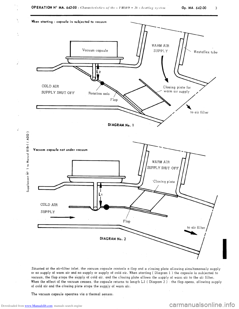
When starting : capsule is subjected to vacuum
Vacuum capsule
Westaflex tube
c J
J
COLD AIR
Closing plate for
SUPPLY SHUT OFF warm air supply
,
Flap B
I
to air filter
DIAGRAM.No. 1
‘acuum capsule not under vacuum
Flap
DIAGRAM No. 2
to air filter
Situated at the air-filter inlet. the vacuum capsule controls a flap and a closing plate allowing simultaneously supply
or no supply of warm air and no supply or supply of cold air. When starting ( Diagram 1 ) the capsule is subjected to
vacuum, the flap stops the supply of cold air, and the closing plate allows the supply of warm air to the air filter.
When the effect of the vacuum ceases, the capsule returns to length Ll ( Diagram 2 ) : the flap.opens, allowing supply
of cold air and the closing plate stops the supp[y of warm air.
The vacuum capsule operates via a thermal sensor.
Page 379 of 394

Downloaded from www.Manualslib.com manuals search engine B. THERMAL SENSOR
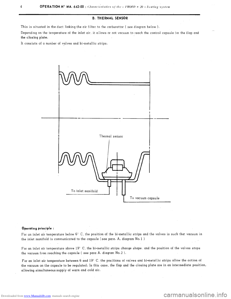
This is situated in the duct linking the air filter to the carburettor ( see diagram below ).
__
Depending on the temperature of the inlet air. it allows or not vacuum to reach the control capsule for the flap and
the closing plate.
It consists of a number of valves and bi-metallic strips.
To inlet manifoldb-yTu-4
I To vacuum capsule Operating principle :
For an inlet air temperature below 6’ C, the position of the bi-metallic strips and the valves is such that vacuum in
the inlet manifold is communicated to the capsule (see para. A, diagram No. 1 )
For an inlet air temperature above 19” C, the bi-metallic strips change shape. and the position of the valves stops
the vacuum from reaching the capsule ( see para A. diagram No.2 ).
For an inlet air temperature between 6 and 19” C, the positions of valves and bi-metallic strips allow the action of
the vacuum on the capsule to be regulated. In this case, the flap and the closing plate are in an intermediate position,
allowing simultaneous supply of warm and cold air.