Page 258 of 394

Downloaded from www.Manualslib.com manuals search engine 2 OPERATION No MA. 430-O : ~hwki~zg nrtd nrijustittg the suspwrsiott ntd its cotttrol
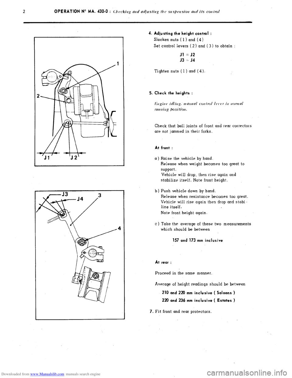
4. Adjusting the height control :
Slacken nuts ( 1) and (4 )
Set control levers ( 2 ) and ( 3 ) to obtain :
Jl = J2
J3 = J4
Tighten nuts ( 1 ) and (4).
5. Check the heights :
Ertgittv icilittg. tttnttt~nl cotttrol Ic,t’c,r itt ttotvttO/
rtrrtttiug positiott.
Check that ball join!s of front and rear corrqctors
are not jammed in their forks.
At front :
a) Raise the vehicle by hand.
b Release when weight becomes too great to
support.
Vehicle wi1.l drop, then rise again and
stabilize itself. Note front height.
Push vehicle down by hand
Release when resistance becomes too great.
Vehicle will rise again then drop and stabi-
lize itself.
Note front height again.
c) Take the average of these two measurements
which should be between
157 and 173 mm inclusive
At rear :
Proceed in the same manner.
Average of height readings should be between
210 and 220 mm inclusive ( Saloons )
220 and 236 mm inclusive ( Estates )
7. Fit front and rear protectors.
Page 268 of 394
Downloaded from www.Manualslib.com manuals search engine d
m
.-
0
2
f Op. MA. 440-00
7 -
b) Steering governor :
It is situated on the front subframe, and mechanically driven ( cable ) by the final drive unit in the gearbox.
Ei A ”
VEHICLE STOPPED (engine running)
L.44-14b
I/ /II I Pressure
IL Towards
HP cam cylinder
VEHICLE IN MOTION
* Slide-valve A is linked in linear motion to lever B
- Fly-weights C, which rotate ( and fly towards under the effect of centrifugal force ) cause lever B to tilt.
=
L'nrioblc, position of slide-valve A, allows the pressure exerted on the cam cylinder piston to be varied.
NOTE In order to make possible the powered return function. the steerinq governor supplies a pressure
of 20 i-15 bars ( 290 +173 psi ) when the vehicle is stopped f 11
i/F /hc cwgir/e wt/t~iv.g i.
I
POWERED RETURN
The powered return is a combination of the two preceding functions, the variable feel function controlling the
power-operation function.
Page 361 of 394

Downloaded from www.Manualslib.com manuals search engine AIR-CONDITIONING
CHARACTERISTICS AND SPECIAL FEATURES OF THE AIR-CONDITIONING SYSTEM
The air-conditioning system includes the refrigeration and the heating of the air drawn into the passenger compart-
ment. REFRIGERATION
This allows the air in the passenger compartment to be cooled, while at the same time reducing its dampness (and
therefore the misting up of the glass ) HEATING
It is of the (( FROID - 15)) or (( FROID - 20 )) type
1 The air is blown around the channels of a radiator supplied by water from the engine cooling system.
&
co
5
3
t
E REFRIGERATION
E I. CHARACTERISTICS
ASPERA FRIGO type HG 700 or
Compressor
1 .
SANKYO * type SD 508
De-watering tank . SINGER
Condenser _.. ._..: _._...... . . . . . . . . . . . CHAUSSON
Evaporator-blower , SOFICA
Flexible hoses ..,_.,....,............................................................................... STRATOFLEX and RANCO
Refrigerating fluid . R. 12 Weight
of refrigerating fluid _..._.._._._..,_..__.................................................... 1 kg ( 2.2 lbs )
Oil for lubricating compressor TOTAL LUNARIA 25 or SUNISO No. 5
or TEXACO CAPELLA (( E )) grade 500
Quantity of oil for lubricating compressor ,
280 g i.e. a height of 21 to 29 mm
f
CJSCC,~~ ior SANKYO UIVI~WSSO~ J
* Only fitted on vehicles fitted with converter and air-conditioning option.
Page 387 of 394

Downloaded from www.Manualslib.com manuals search engine OPERATION No MA. 852-O : Adius/ir,y I/><, bo,,r,r/ Op. MA. 852-O 1
~.
I. ADJUSTING THE BONNET
I. Height adjustment :
Remove screws (2) securing bonnet hinge to the
body.
Position suitable shims at u a )) to ensure the
recess of bonnet in relation to front wings : R = 2 mm max.
Fit and tighten screws (2 ). 2. Transversal and longitudinal adjustment :
Loosen hinge fixing screws ( 1 ) on bonnet
Adjust them in order to obtain a clearance
between bonnet and wings : J=6
+ 2.5
-1 mm
- with (I maximum difference of 2.5 mm between
left and right-hand sides and a maximum diffe-
rence in level of 2 mm,
- adjust also to obtain clearance between front
edge of wings and bonnet : E = 0 it3 mm
3. Adjusting the striking plate :
Loosen screws ( 3 )
Centre striking plate in relation to lock.
Tiqhten screws ( 3 ). 4. Adjusting the safety catch :
Loosen screw5 (4 1.
Adjust safety catch so that :
With bonnet resting on catch, the latter must engage
under weight of bonnet alone.
Tighten screws (4 ). 5. Adjusting the lock and lock control cable :
Remove scravs (6 ) and (7 ) and protective
plate (5).
Loosen screws (8) and adjust height of lock
in order to ensure, recess R, at the front.
Tension lock control cable by screwing nut (9 )
to eliminate any clearance on bonnet opening
leV%. Bonnet should lock correctly when dropped
from (I height of 250 mm.
Page:
< prev 1-8 9-16 17-24