1980 SKODA 120 LSE horn
[x] Cancel search: hornPage 12 of 238
Worrring
lights:
5 -
left-hond direction indicotors, green
6 -
oil pressure,
red
7 -
right-hond direction indicotors, green
8 -
broke system, red
9 -
chorging, red
10 -
fuel reserve, omber
11 -
high beom, blue
The thermometer indicotes the temperoture
of the coolont with the ignition switched on.
The optimum operoting temperoture ronge is
from 75 to 105oC. In
SfOon 105 S, this
ronge
is identified by
the green
zone of the scole.
The fuel gouge
indicotes the level
of the fuel
with the ignition switched on. The scole is
provided with divisions 0 -
r/2
-
1, i. e., empty,
holf full,
ond full
tonk.
The driver is worned by the red worning light
when thene ore less thon 5litres of fuel in the
fuel tonk.
The tochometer indicotes the speed (revol-
utions) of the engine. The
speed should
never
rise to the red zone. When chonging the geors,
on increose of speed within the ronge
of the
yellow zone is permissible.
The porking
lights come on when the switch
is thrown to the first
right-hond position.
The
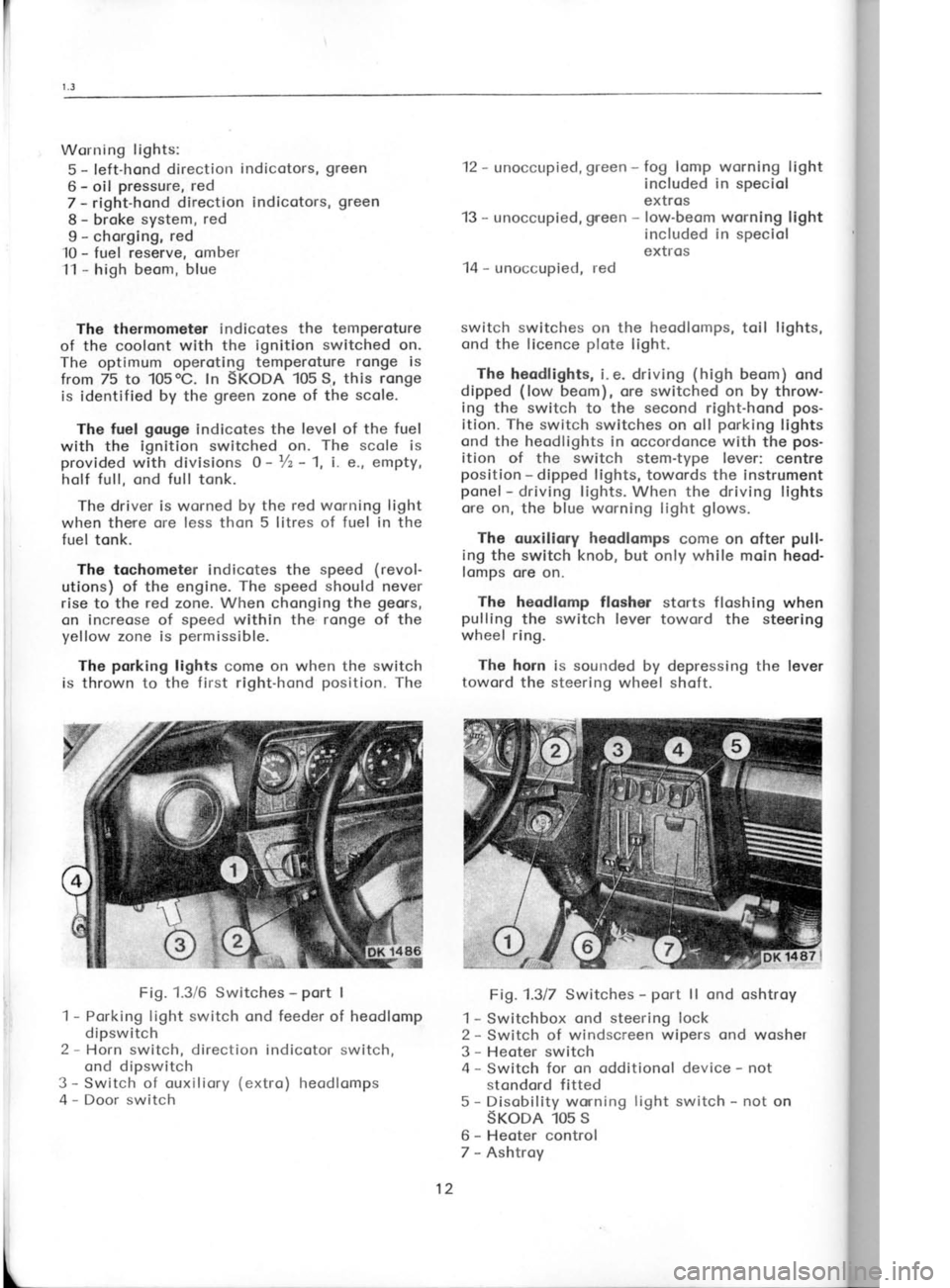
Fig. 1.3/6 Switches -
port I
1 -
Porking light switch ond feeder of heodlomp
dipswitch
2 -
Horn switch, direction indicotor switch,
ond dipswitch
3 -
Switch of ouxiliory (extro)
heodlomps
4 -
Door switch 12
-
unoccupied, green -
fog lomp worning light
included in speciol
extros
13 -
unoccupied, green -
low-beom worning light
included in speciol
extros
14 -
unoccupied, red
switch switches on the heodlomps, toil lights,
ond the licence plote
light.
The heodlights, i. e. driving (high
beom) ond
dipped (low
beom), ore switched on by throw-
ing the switch to the second
right-hond pos-
ition. The switch switches on oll porking
lights
ond the heodlights
in occordonce with the pos-
ition of the switch stem-type lever: centre
position -
dipped lights,
towords the instrument
ponel -
driving lights. When the
driving lights
ore on, the blue worning light glows.
The ouxiliory heodlomps
come on ofter pull.
ing the switch knob, but only while moin
heod-
lomps ore on.
heodlomp flasher storts floshing
when
the switch lever
toword the steering
ring.
horn is sounded by depressing
the lever
the steering wheel shoft.
Fig.1.317 Switches -
port ll ond oshtroy
1 -
Switchbox ond steering lock
2 -
Switch of windscreen wipers ond
wosher
3 -
Heoter switch
4 -
Switch for on odditionol device -
not
stondord fitted
5 -
Disobility worrning light
switch -
not on
SKoDA 105 s
6 -
Heoter control
7 -
Ashtroy
The
pulling
wheel
The
toword
i
I
L 12
Page 141 of 238
r 0.3-t0,5
Ihe permissible
out-of-bolonce must not ex-
ceed 50 grommes
on the rim rodius. Every new
tyre is provided
with o coloured dot on its side,
indicoting its lightest point.
Fit the tyre olwoys
with this dot focing
the tube volve.
ln this
position, the volve octs os on odditionol weight
compensoting the wheel overoll unbolonce to
o consideroble extent.
lf dynomic boloncing of the wheel is not
possible, bolonce the wheel stoticolly with the
greotest possible qssuroc|.
Boloncing weights
of 30, 50, 75,
ond 100 grommes
ore ovoiloble.
10.4 TUBED TYRES
For mounting,
dismounting,
ond repoirs of
conventionol tyres with inner tubes (for
por-
ticulors, see the preceding
Chopters), the usuol
procedures ore opplicoble. The permissible run-
out (untrue
running)
of the rim is the some os
for tubeless tyres (Chopter
10.5).
10.5 TUBELESS TYRES
The oir-tight seoling of these tyres requires
more core ond o different hondling thon thot of
the tyres with inner
tubes.
Preporotlon of Rirrr
13elore mounting the tyre, inspect the rim for
ony technicol defects. The points
to be checked
ore the rim shoulder ond the moting foce for
the tyre beods,
in oddition to the overoll con-
dition of the rim. lf ony defects ore found, the
rim must be reconditioned.
A sotisfoctory rim
nrust comply with the following conditions:
o) The
rim shoulder ond the tyre volve hole
must not be distorted;
there must be no
shcrp edges or protrusions
likely to domoge
the tyre beod. Minor unevennesses
con be
hornmered flot ond smoothed
with o file.
The moximum eccentric running
of the rim
side must not exceed 1.5 mm.
b) The moting surfoces
must be obsolutely
cleon (free
from stuck-on rubber, rust,
etc.).
Cleon them with emery poper
or o wire brush
ond coot them with point.
lnstolling of Tyre
Volve
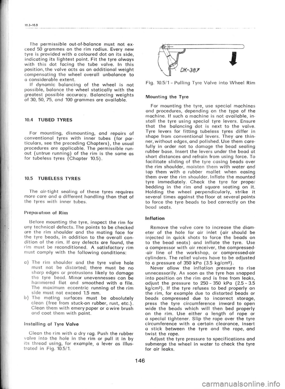
Cleon the rim with o dry rog. Push
the rubber
volve into
the hole in the rim
or pull
it in
by
its threod using, for exomple,
o lever
os illus-
troted in Fig. 10.5/1. Fig. 10.5/1
-
Pulling Tyre Volve
irrto Wheel Rim
Mounting the Tyre
For mounting the tyre, use speciol mochines
ond procedures,
depending on the type of the
nrochine. lf such o mochine is not ovoiloble, in-
stoll the tyre using speciol tyre levers.
Ensure
thot the boloncing dot is next to the volve.
Tyre leverrs for fitting tubeless tyres
differ in
shope from conventionol levers. They
ore thin-
ner, without edges, ond polished.
Use them core-
fully in order not to domoge the
beod seoling
rubber bose. Insert the levers
under the beod
ot
short distonces ond refroin from using force. To
focilitote sliding of the tyre cosing beods over
the rim shoulder, moisten them with woter ond
top them with o rubber
mollet when eosing
them over the rim shoulder. Inflote
the mounted
tyre immediotely. Check the tyre for propei'
bedding in the rim ond
squore seoting
on it.
Holding the wheel perpendiculorly,
strike it
severol times ogoinst the f loor ot severol points
to force the tyre beods
to bed
correctly on the
bcad seots.
lnf lotion
Remove the volve
core to increose
the diom-
eter of the hole for oir inlet (oir
should be
iniected in quick
shots to force
the beods
on
to the beod seots) ond inflote the tyre. Use
o compressor with oir receiver, the
compressed-
.oir line of the
workshop, or
compressed-oirr
cylinders. The relief volves hove to be odiusted
to o pressure
of 350 kPo (3.5
kg/cmz).
Never ollow the inflotion pressure
to rise
unnecessorily. As soon os the tyre hos snopped
into position
on the rim
ond is free from leoks,
odiust the pressure
to 250 -
350 kPo (2.5 -
3.5
kg/cmz). lf the tyre refuses to
bed properly
on
the rim,
for exomple due to distorted beods or
beods compressed due to incorrect storoge,
press the tyre circumference inword to open
wide the beods which will then bed properly
on the rim. Use either o length of
rope or
o speciol tightener. Slip the rope over the
tyre
circumference with o certoin cleoronce, insert
o stick
between the tyre ond the rope, ond
twist the rope.
Adiust the tyre pressure
to specif
icotions ond
submerge the wheel in woter to check the
tyre
for oir leoks.
146
Page 161 of 238
1
1
1
1
1
1:
1r
1l
't,
1',
1:
1:
1l?
ffi{,
ll
---r---
i
fdll
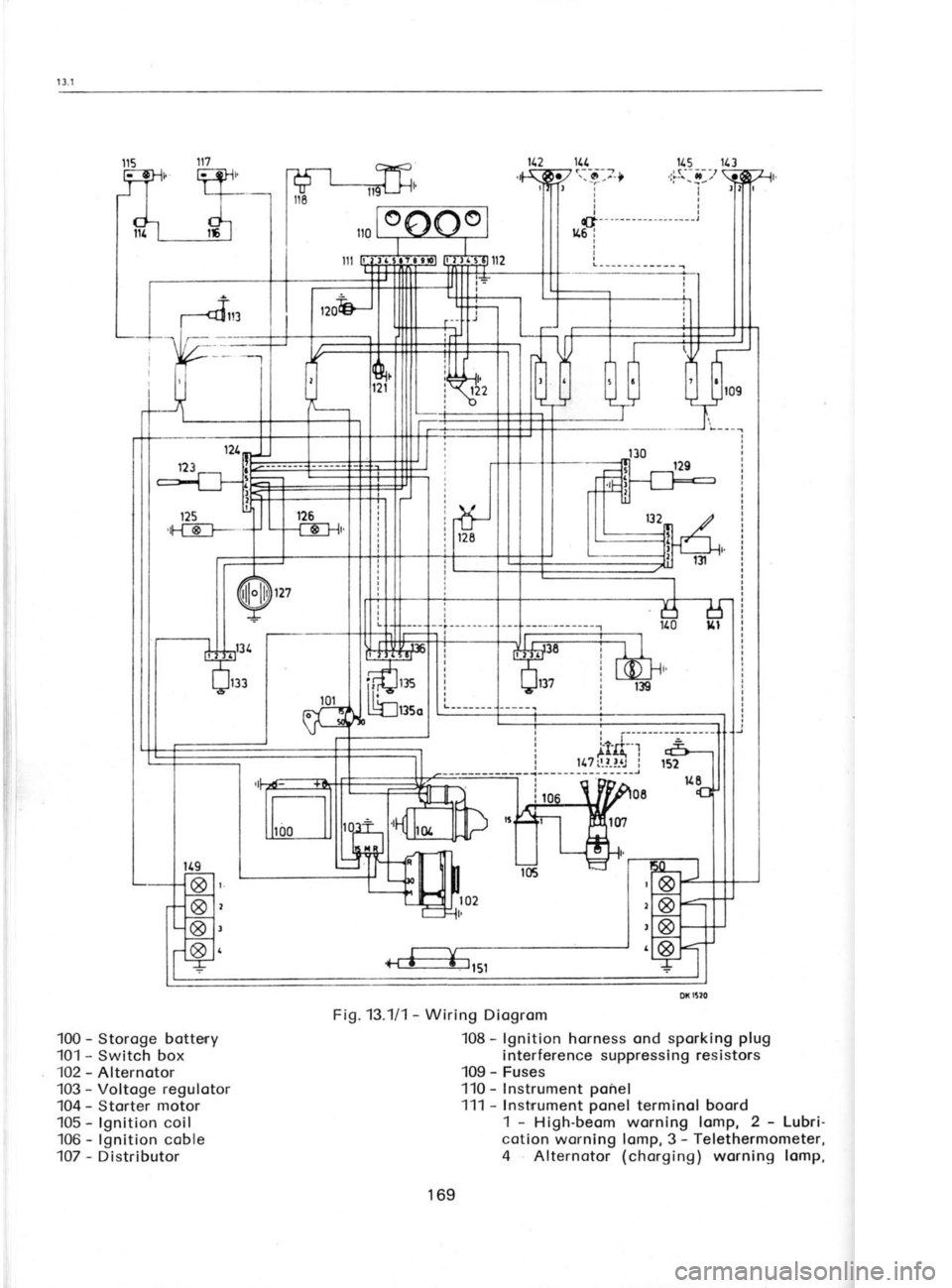
100 -
Storoge botteny
101 -
Switch box
102 -
Alternotor
103 -
Voltoge regulotor
104 -
Storter motor
105 -
lgnition coil
106 -
lgnition coble
107 -
Distributor 115
113
'l7s:,!--,t
ir
rl
tl
tl
t|- -
- --
- - -- - - --- --- -l
116 i
I
I
L--_-___---__ I
Fig. 13.111 -
Wiring Diogrom
108 -
lgnition horness ond sporking plug
interference suppressing resistors
109 -
Fuses
'110 - Instrument ponel
111 -
Instrrument ponel
terminol boord
1 -
High-beom worning lomp, 2 -
Lubri-
cotion worning lomp, 3 -
Telethermometer,
4 Alternotor (chorging)
worning lomp,
169
Page 165 of 238
'i
iiiI 14. Fuse box
Centrol connection of conductors -
do not
seporote them from the bunch!
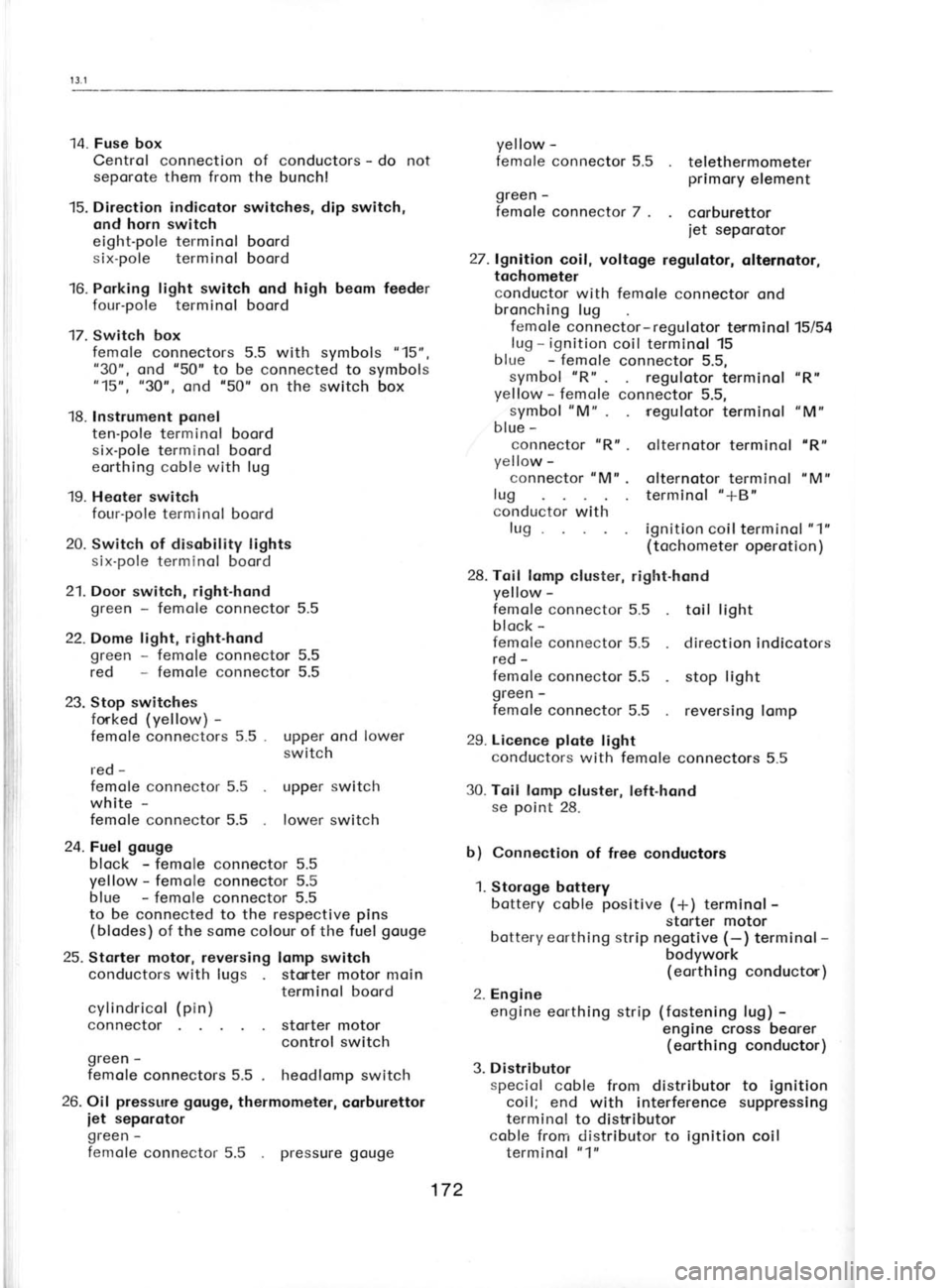
15. Direction indicotor switches, dip switch,
and horn switch
eight-pole terminol
boord
six-pole terminol boord
16. Porking light switch ond high beom feeder four-pole terminol boord
17. Switch box femole connectors 5.5 with symbols "15",
"30", ond '50"
to be
connected to symbols
"15u, "30', ond '50"
on the switch box
18. Instrument ponel
ten-pole terminol boord
six-pole terminol boord
eorthing coble with lug
'19. Heoter switch
four-pole terminol boord
20. Switch of disobility lights
six-pole terminol boord
21. Door switch, right-hond
green -
femole connector 5.5
22. Dome light,
right-hond
green -
femole connector 5.5
red -
femole connector 5.5
23. Stop switches
forked (yellow) -
femole connectors 5.5 .
red -
femole connector 5.5
white -
femole connector 5.5upper ond lower
switch
upper switch lower switch
24.Fuel gouge block -
femole connector 5.5
yellow -
femole connector 5.5
blue -
femole connector 5.5
to be connected to the respective pins
(blodes) of the some colour of the fuel gouge
25. Storter motor, reversing
lomp switch
conductors with lugs stater motor moin
terminol boord
storter motor
control switch
green -
femole connectors 5.5 heodlomp switch
26. Oil pressure
gouge,
thermometer, corburettor
iet seporotor
green -
femole connector 5.5 yellow
-
femole connector 5.5
green - telethermometer
primory element
femole connector 7.
corburettor
iet seporotor
27. lgnition coil, voltoge regulotor, olternotor,
tochometer
conductor with femole connector ond
bronching lug
femole connector-regulotor terminol 15/54
lug -
ignition coil terminol 15
blue -
femole connector 5.5,
symbol "R"
. regulotor terminol "R"
yellow -
femole connector 5.5,
symbol "M"
regulotor terminol "M"
blue -
connector "R"
. olternotor terminol "R"
yellow -
connector "M".
olternotor terminol "M"
lug terminol "+B"
conductor with
lug ignition coilterminol "1"
(tochometer operotion
)
28. Toil lomp cluster, right.hond
yellow -
femole connector 5.5 toil light
block -
femole connector 5.5 direction indicotors
red -
femole connector 5.5 stop light
green -
femole connector 5.5 reversing lomp
29. Licence plote light
conductors with femole connectors 5.5
30. Toil lomp cluster, left.hond
se point
28.
b) Connection
of free conductors
1. Storoge bottery
bottery coble positive
(*)
terminol -
storter motor
bottery eorthing strip negotive (-)
terminal -
bodywork (eorthing conductor)
2. Engine engine eorthing strip (fostening
lug) -
engine cross beorer (eorthing conductor)
3. Distributor speciol coble from distributor to
ignition
coil; end with interference suppressing
terminol to distributor
coble from distributor to ignition coil
terminol "1"
cylindricol
(pin)
connector
pressure gouge172
Page 177 of 238
1 3.9-1
3.10
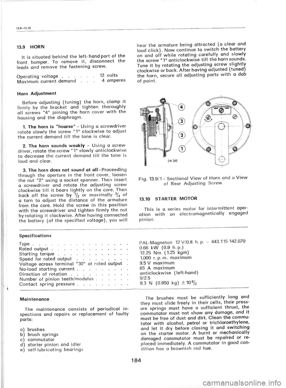
13.9 HORN
It is situoted behind
the left'hond port of
the
front bumper. To
remove it, disconnect the
leods ond remove the
fostening screw. heor
the ormoture being ottrocted (o
cleor ond
loud click). Now continue to
switch the bottery
on ond off
while rototing
corefully ond
sloryly
the screw "1"
onticlockwGe till
the
horn sounds'
iune it by rototing the odiusting.:cr9ry slightly
clockwise or
bock.-After hoving
odiusted (tuned)
ih" honn, secure
oll
odiusting ports with
o
dob
of point.
12
volts
4 omperes
Operoting
voltoge
Moximum current demond
Horn Adiustment
Before odiusting (tuning) the
horn, clomp it
firmly by th'e brocket ond
tighten thoroughly
oll screws "4"
ioining the
horn cover
with the
housing ond the dioPhrogm.
1. The horn is "hoorse"
- Using o screwdriver
rotote slowly the screw "1"
clockwise to odiust
the current demond
till the tone is cleor.
2. The horn sounds weokly -
Using o screw-
driver, rotote the screw "1"
slowly onticlockwise
to decreose the current demond
till the tone is
loud ond cleor.
3. The horn does not sound ot oll-Proceeding
through the operture in the front cover, loosen
the nut "2"
using o socket
sPonner. Then
insert
o screwdriver ond rotote
the odiusting screw
clockwise till it
beors lightly on the core. Then
bock off the screw by 1lz
or moximolly 3/a
of
o turn to odiust the distonce
of the ormoture
from the core. Hold the screw in this position
with the screwdriver ond
tighten firmly the nut
by rototing it clockwise. After hoving
connected
the bottery (of
the specified voltoge), you
will Fig.
13.9/1 -
Sectionol View
of Horn ond
o View
of Reor
Adiusting Screw
13.10 STARTER MOTOR
This is o series motor for
intermittent oper-
otion with on
electromogneticolly engoged
pinion. -@
c@c
Specif icotions
TyPe Roted outputStorting torqueSpeed for roted output
Voltoge ocross terminol
No-lood storting current
Direction of rototion
Number of pinion
teeth/modulus .
Contoct spring pressure PAL-Mogneton
12 V/0.8
h.
p. -
443'115'142'070
0.66 kw (0.e h.
P.)
12.25 Nm (1.25
kgm)
'1,000 r. p.
m. moximum
9.5 V moximum
65 A moximum
onticlockwise (left'hond)
912.5
e.3 N (0.ss0 ks) +100/6
"30"
of roted output
Mointenonce The mointenonce consists of periodicol
in'
spections ond repoirs or replocement of foulty
ports:
o) brushes
b) brush springs
c) commutotord) storter pinion ond idler
e) self-lubricoting beorings The brushes
must
be sufficiently long
ond
they must slide
freely in
their-cells, their
press-
ure springs must hove o
sufficient thrust,
the
commutotor must not
show ony
domoge, ond
it
must be
free of dust ond dirt.
Cleon the
commu-
totor with olcohol, petrol or
trichloroethylene,
ond let it dry before closing it
ond switching
on the storter motor. A
burnt or mechonicolly
domoged commutotor must
be repoired or
re'
ploceJ immediotely. A commutotor in
good con'
dition hos o brownish red
hue.
184
Page 187 of 238
1 3.1 6-t 3.1
7
focio ofter removing two
copscrews ol-l the
ponel bottom. lt moy
be olso necessory to pull
off the heoter control push
buttons.
c) Switch of disobility worning lights
For fostening see
informotion sub
b). -l
he
switch operotes only
when connected to the
direction indicotor ticker.
d) Dipswitch, direction indicotor, horn, wind-
screen wiper, ond winscreen wosher switch
ox 1568
instolled on
the steering
fostened to
the reduction
with shoft
beorings ond to
steering wheel shoft
shroud.
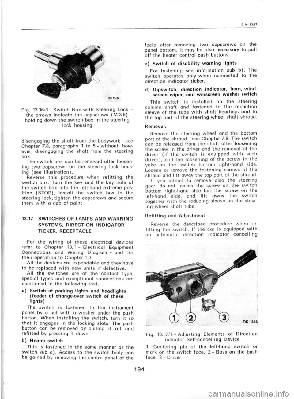
Fig.
13.16/1 -
Switch Box with Steering Lock -
the orrows indicote the copscrews (M
3.5)
holding down the switch box in the steering
lock housing
disengoging the shoft from
the bodywork -
see
Chopter 7.8, porogrophs
1 to 5 -
without, how-
ever, disengoging the shoft from
the steering
box. The switch box con be removed
ofter loosen-
ing two copscrews on the steering lock hous-
ing (see
illustrotion).
Reverse this procedure
when refitting the
switch box. Turn
the key ond
the key hole of
the switch box into the left-hond extreme pos-
ition (STOP),
instoll the switch box in the
steering lock,tighten the copscrews ond secure
them with o dob of point.
13.17 SWITCHES OF LAMPS
AND WARNING
SYSTEMS, DIRECTION INDICATOR
TICKER, RECEPTACLE
For the wiring of these electricol devices
refer to Chopter 13.1 -
Electricol Equipment
Connections ond Wiring Diogrom -
ond for
their operotion to Chopter 1.3.
All the devices ore expendoble ond they hove
to be reploced with new units if defective.
All the switches ore of the contoct type,
speciol types ond exceptionol connections ore
mentioned in the following text.
o) Switch of porking
lights ond heodlights
(feeder of chonge-over
switch
of these
lights)
The switclr is fostened to the instrument
ponel by o nut with o wosher under the push
button. When instolling the switch,
turn it so
thot it engoges in the locking slots. The push
button con be removed
by pulling
it off ond
refitted bv pressing
it down.
b) Heoter switch
This is fostened in the some monner
os the
switch sub o). Access to the switch
body con
be goined
by removing the centre ponel
of the This switch
is
column shoft ond
sleeve of the tube
the top port
of the
Removol: Remove the steering wheel
ond the bottom
port of the shroud -
see Chopter 7.8.
The switch
con be releosed from the shoft ofter loosening
the screw in the driver ond the removol of the
driver (
if the switch is equipped with
such
driver), ond the loosening of the
screw in the
yoke on the switch bottom right-hond side.
Loosen or remove the fostening screws of
the
shroud ond lift owoy the top port
of the shroud-
lf you
intend to remove olso the
steering
geor, do not loosen the screw
on the switch
bottom right-hond side but the screw on the
left-hond side, ond lift
owoy the switch
together with the reducit-tg
sleeve on the steer-
ing wheel shoft tube.
Refitting ond Adiustment
Reverse the described procedure when
re-
fitting the switch. lf the cor is equipped with
:" outomotic
direction
indicotor concelling
Fig. 13.1711- Adiusting Elements of
Directiorr
lndicotor Self-concelling Device
1 -
Centering pin
of the left-hond
switch or
mork on the switch foce, 2 -
Boss on the bush
foce, 3 -
Driver
194
Page 193 of 238
1 t.1
-1
4.3
surfoces ore
sproyed with o
Protective com'
pound. The floor boords including the floor of
the boot ore covered with textile corpets while
rubber mots ore used in Skodo 105 S.
The in-
terior luggoge comportment is
lined with insu-
loting felt
sheet.
fne body finish consists of severol loyers of
speciol onti-corrosive cootings, o primer
coot,
ond o synthetic boking enomel top
coot in
colours complying with
o speciol specificotion.
14.1 BUMPERS
To Remove Front BumPer
Disconnect the
leods of the horn ond front
direction indicotors. Remove bolts connecting
the side sections of
the bumper with the wings
ond bolts of the bumper brockets, connecting
them to the wheel splosh guords. Now
the
entire bumper is free ond it con be removed.
Te Remove Reor BumPer
Proceed in the some woy with the exception
thot there ore no leods to be disconnected.
To Remove Overriders
Screw off the nut M 10 ond lift owoy the
overri der.
14.2 WTNGS
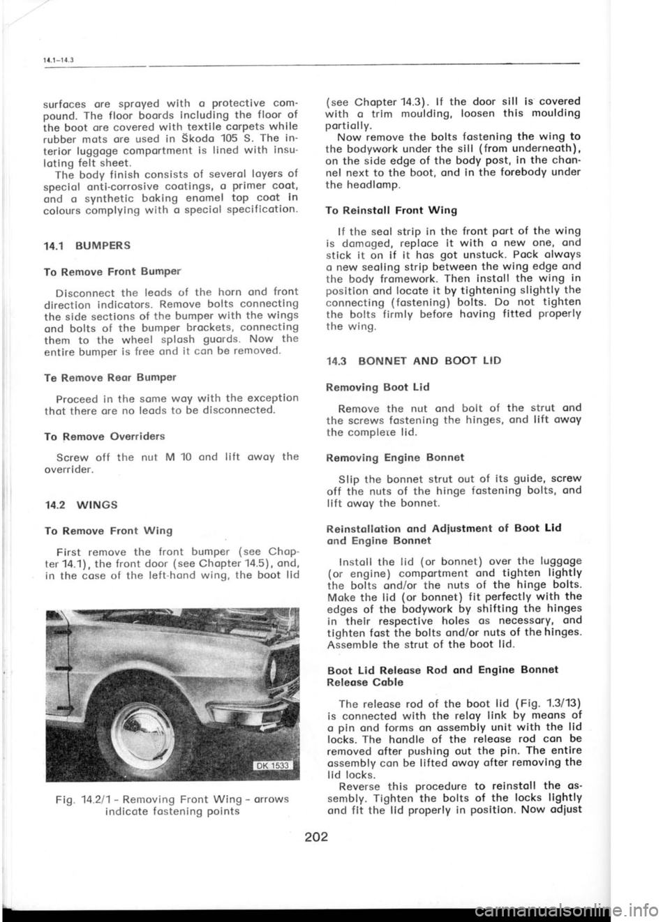
To Remove Front Wing
First remove the front bumper (see
Chop-
ter 14.1), the front door (see
Chopter 14.5), ond,
in the cose of the left-hond wing, the boot lid
Fig. 14.211- Removing Front Wing -
orrows
indicote fostening points (see
Chopter 14.3). lf the door sill is covered
with o trim moulding, loosen this moulding
portiolly. Now remove the bolts fostening the wing to
the bodywork under the sill (from
underneoth),
on the side edge of the body post,
in the chon'
nel next to the boot, ond in the forebody under
the heodlomp.
To Reinstqll Front Wing
lf the seol strip in the front
Port of the wing
is domoged, reploce it with o new one, ond
stick it on if it hos got
unstuck. Pock olwoys
o new seoling strip between the wing edge ond
the body fromework. Then instoll
the wing in
position ond locote it by tightening slightly the
connecting (fostening) bolts.
Do not tighten
the bolts firmly before hoving fitted properly
the wing.
14.3 BONNET AND BOOT LID
Removing Boot Lid
Remove the nut ond bolt of the strut ond
the screws fostening the
hinges, ond lift owoy
the complete lid.
Removing Engine Bonnet
Slip the bonnet strut out of
its guide,
screw
off the nuts of the hinge fostening bolts, ond
lift owoy the bonnet.
Reinstollotion ond Adiustment of Boot Lid
ond Engine Bonnet
Instoll the lid (or
bonnet) over
the luggoge
(or engine) comportment ond
tighten lightly
the bolts ond/or the nuts of the hinge bolts.
Moke the lid (or
bonnet) fit perfectly
with the
edges of the bodywork by shifting the hinges
in their respective holes
os necessory, ond
tighten fost the bolts ond/or nuts of the hinges-
Assemble the strut of the boot lid.
Boot Lid Releose Rod ond Engine Bonnet
Releose Coble
The releose rod of the boot lid (Fig.
1.3113)
is connected with the reloy link by meons of
o pin
ond forms on ossembly unit with the lid
locks. The
hondle of the releose rod con be
removed ofter pushing
out the pin.
The entire
ossembly con be lifted owoy ofter removing the
lid locks.
Reverse this procedure
to reinstoll the os'
sembly. Tighten the bolts of the locks lightly
ond fit the lid properly
in positlon.
Now odiust
202 c
o
o
o ir
e
tt d