1980 SKODA 120 LSE clutch
[x] Cancel search: clutchPage 156 of 238

12.6-12.f
2. Proceeding fronr below, rernove
the fuel
tonk sheet guord
ond the guord
of the cooling
woter pipes.
3. Disconnect the pipe
of the clutclr hydroulic
line from the clutch releose hose brocket.
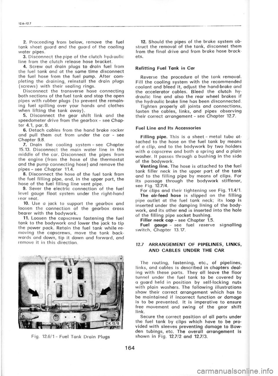
4. Screw out droin plugs
to droin fuel from
the fuel tonk ond ot the some time disconnect
the fuel hose from
the fuel pump.
After com-
pleting the droining, reinstoll the droin plugs
(screws) with their seoling rings.
Disconnect the tronsverse hose connecting
both sections of the fuel tonk ond stop the
open
pipes with rrubber
plugs (to prevent
the remoin-
ing fuel spilling over your
honds ond clothes
when lifting
the tonk owoy).
5. Disconnect the geor
shift link ond the
speedometer drive from the georbox -
see Chop-
ter 4.1, por.9.
6. Detoch cobles from the hond broke rocker
ond pull
them out from under the cor -
see
Chopter 9.8. 7. Droin the cooling system -
see Chopter
-15.13.
Disconnect the moin woter line in
the
rniddle of the cor. Disconnect the pipes
from
the engine (from
the hose of the thermostot
ond the pump
connecting hose) ond remove
the
pipes -
see Chopter 11.4.
8. Disconnect the hose of the fuel
tonk from
the fuel filling pipe, ond, in the upper port,
the
hose of the fuel filling line vent pipe.
9. Sever the electric connection of the fuel
level gouge
floot system under tlre right-hond
I eor seot.
10. Use o
iock to support
tl're georbox
ond
loosen tlre connection of the georbox
cross
beorer with the bodywork.
11. Loosen the copscrews fostening the fuel
tonk to the bodywork ond lower the
iock to tip
the power
pock.
Retoin the fuel tonk while ne-
nroving the copscrews, move the tonk bock-
words ond down, tip it down ond forword, ond
remove it in
this direction. 12. Should
the pipes
of the broke system ob-
struct tlre removol of the tonk, disconnet them
from the finol drive ond from broke hose brock-
ets.
Refitting Fuel Tqnk in Cor
Reverse the procedure
of the tonk removol.
Fill the cooling system with the recommended
coolont ond bleed it, odjust the hond-broke ond
the occelerotor cobles. Bleed the clutch hy-
droulic line
ond olso the reor wheel brokes if
the hydroulic broke line hos
been disconnected.
Tighten properly
oll joints
ond connections,
fosten the cobles, links, ond pipes
obsenving
their correct orrongement -
see Chapter 12.7.
Fuel Line ond lts Accessories
Filling pipe.
This is q
sheet -
metol tube ot-
toclred to
the hose on the fuel tonk by meons
of o clip, ond to
the bodywork by two holders
with o copscrew ond both o spring ond o ploin
wosher. lt posses
througlr o bushing in the side
of the bodywork. Venting line. The hose is ottoched to the fuel
tonk filler neck in the upper port
of the tonk
ond to the filling pipe
by meons
of clips. For
its possoge
through the bodywork stiffener,
see Fig. 12.714. For clips ond their tightening see
Fig. 11.4/1.
The oir-feed hose
is slipped on the filling
pipe outlet ot
the fuel tonk neck; its
loop is
inserted under the domping lining of the body-
work, ond its other end is inserted into the hole
of the filling pipe
socket bushing.
Filler neck cop -
see Chopter 1.5.
Fuel gouge -
see fuel reserve signolling
switch, Chopter 13.17.
12.7 ARRANGEMENT
OF PIPELINES, LINKS,
AND CABLES UNDER THE
CAR
The routing, fostening, etc., of pipelines,
links, ond cobles is described in
chopters deol-
ing with these ports.
They oll leove the floor
tunnel under tlre fuel tonk to
be covered by
o guold
held in position
by self-locking nuts
with ploin
woshers. The following
illustrotions
show their correct orrongement which hos to
be mointoined if incorrect function or domoge
is to be prevented.
lt is imperotive to ensure
free movement ond swing
of the geor
shift
link.
Secure the correct position
of oll ports
under
the fuel tonk by clips which hove
to be pro-
vided with sleeves preventing
domoge to Bow-
den tubings, etc. The overoll orrongement is
shown in
Fig. 12.712 ond 12.713.
Fig.
12.611- Fuel Tonk Droin
Plugs
164
Page 210 of 238

tificotion
number, or in
words. For exomple
Mobiloil 30 is on oil in the SAE 30 viscosity
closs, Mobiloil Speciol belongs to the SAE
10 W/30 closs. We quote
the viscosity closs
symbol of oils identified
in this woy in brockets
following the oil brond (trode
nome).
Oils designoted by o doubled viscosity closs
symbol ore the so-colled multigrode oils. Their
complionce with viscosity clossificotion is ex-
pressed by the symbol before the froction line
progressively to the clossificotion expressed by
the symbol behind the froction line. Thus,
for
instonce, the SAE 10W/30 oil hos the properties
of the sAE 10w, sAE 20w120,
ond sAE 30
closs.
Czechoslovok oils
Motor oil M6 AD (SAE
30), M4AD (SAE
20W/
20), Mogul Super SAE 20W50,
Mogul Speciol
SAE 2OW/30
Modit Oil SAE 30 (M6
AD), Modit Oil SAE
2OWl2O (M4AD), Modit Oil Speciol
SAE 10W/
30, Modit Super SAE 10W/40
Foreign oils
Agip: Agip F. 1 Motor Oil HD SAE 10W/20,
2OWl30, 4Ol5O; Agip F. 1
Super Motoroil
10w/40,20wl50
BP: Energol HD SAE 40, 30, 2OW (2OW|?O),
10W; Super Visco-Stotic 10Wi30, 10W/40,
20wt20
Costrof : Costrol 40,
30, 20Wl2O, '10
W; Costrolite
(SAE 10W/30), XL (SAE 20W/50);
GTX
(SAE 10w/50)
Mobil: Mobiloil 40, 30, 2OWl2O,
10W; Speciol
(SAE 10W/30); Speciol 20W/50; Super (SAE
10w/so)
Shef l; X-100 40, 30, 2OWl20,
10W; Super (SAE
10w/so)
Other oils of foreign moke con be used if equi-
volent to the listed bronds, for
exomple, Avio,
Esso, Heno (Optimol
LD), INA (Delto TLX),
Noftogos (Golox GTX, Omnio) etc.
GEAR OILS -
type E. P. (high-pressure)
I Viscosity j Ambient
Lubricoting noint
I closs
! temperoture
sAE 140*) -r50
to +15 oC
Georbox/f inol
drive SAE
90
*35 to -15
oC
* 5 to -30oC
SAE 80
teering box SAE 90 throughout
the yeor Czechoslovok
oils
PP 90 (SAE
90) geor
oil; PP 80 (SAE 80)
geor oil
Foreign oils
Agip: F. 1 Rotro 140; 85/90; 75Wl8O
BP: Geor Oil 140
EP; 90 EP; 80 EP
Costrol: Hypoy B 140; B 90; B 80
Mobil: Mobilube GX 140; GX 90; GX 80
Shell: Spirox E. P. 140; E. P. 90; E. P. 80 W
Other geor
oils of foreign moke con be used
if equivolent to the listed oils.
SPECIAL OILS
Distributor beorings (service inspection)
Czechoslovok moke -
ON 1 low'pour-point oil
Foreign moke -
for exomple, Shell Clovus 17
ond similor oils
GREASES -
use throughout the yeor
Woter pump
Czechoslovok moke -
SP 4 sooP greose,
NH 2
or A4 motor greose
Front wheel beorings, geor lever
brocket
Czechoslovok moke -
SP 4 or NH 2 soop greose
King pins
Czechoslovok moke -
A 00 motor greose
Inner door mechonisms, locking mechonisms
Czechoslovok moke -
SP 2-3 soop greose*)
Clutch releose beoring
Czechoslovok moke -
SP 4 or NH 2 soop
greose* )
Steering tinkoge boll
ioints, cronkshoft
beoring
Greoses listed in the porogroph
on greoses
of
foreign moke
Greoses of foreign moke:
Agip: F.1 Greose 30; BP: Energreose L2; Costrol:
Costroleose l. M.; INA: Automost Speciol;
Mobil: Mobilgreose MP;
Shell: Retimox A,
ond other greoses
equivolent to
the listed
ones.
BRAKE FLUID
To SAE J 1703C Specificotion
ln Czechoslovokio -
SYNTOL HD 190 broke fluid
Abrood -
SYNTOL HD 190, Pentosin
Super Fluid,
Mobil Hydroulic Broke Fluid, ATE Blou, BP
Broke Fluid, STOP SP 19
r) Greoses of foreign moke should be preferred.
220
*)
Not used
in Czechoslovokio
Page 216 of 238

friction focing. lnodequote
ploy
results irr o too
short free trovel of the clutch pedol
ond on
olmost immediote clutch disengogement. Access
to the releose
cylinder con be goined
os de-
scribed in the previous porogroph
on clutch
lubricotion. Hold the rod protruding from
the
relose cylinder ond force
from it corefully the
releose lever, ogoinst which it is restingi
the
lever con be relieved by disengoging the ten-
sion (pull-off
) springs.
ln service, the forcing-off
must be ot leost
2 mm. Adiust it to 4
to 5 mm by odiusting the
length of the rod. After hoving
loosened the nut
on the rod
of the releose cylinder, rotote
the
releose finger to obtoin the correct rod
length.
Then retighten the nut, thus locking the releose
f inger in its position
on the rod.
lf the ploy
is correctly od justed,
the f ree
trovel of the
clutch pedol
pod should ronge
from 40 to 50 mm. lt should not be ollowed to
drop below '!0
to 15 mm. lf the described od-
justing procedure foils to bring the required
result, it is necessory to odjust the clutch
mech-
onism in occordonce with
informotion con
toined in Chopter 3.2.
Bleeding the Glutch Hydroulic System
The movement of the clutch pedol
is trons-
mitted hydroulicolly to the clutch releose cylin-
der. The couses ond symptoms of penetrotion
of oir into the hydroulic
system (similor
to the
broke hydroulic system) ore described in detoil
in the section deoling with brokes. The pro-
cedure of bleeding the clutch is the some os
wherr bleeding the brokes -
see Chopter 15.8.
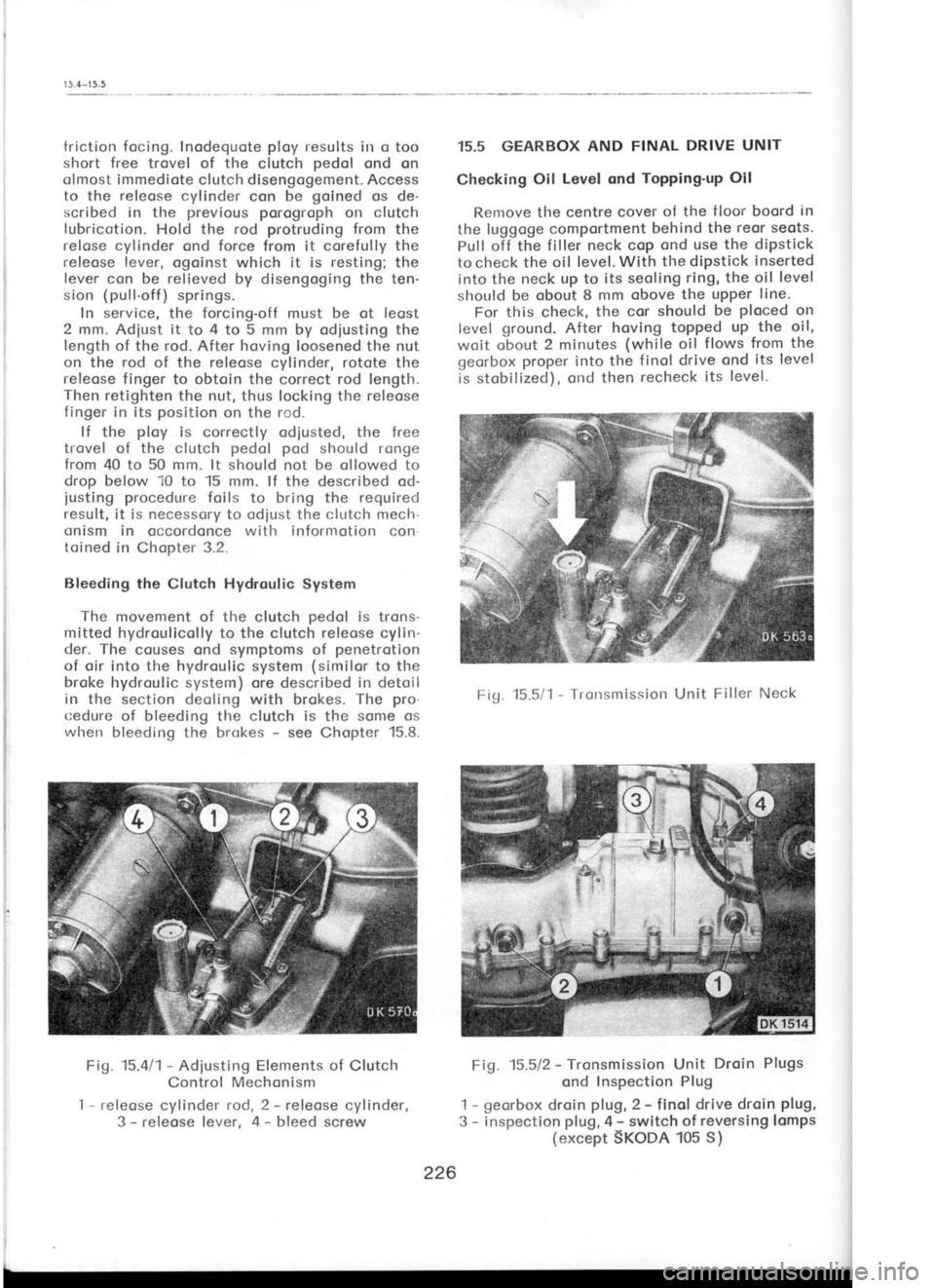
Fig. 15.411-
Adiusting Elements of
Clutch
Control Mechonism
I -
releose cylinder rod, 2 -
releose cylinder,
3 -
releose lever, 4 -
bleed screw 15.5 GEARBOX
AND FINAL DRIVE UNIT
Checking Oil
Level ond Topping'up
Oil
Renrove the centre cover ol the
f loor boord in
the luggoge comportment behind the
reor seots.
Pull off the filler neck cop ond use
the dipstick
to check the oil level. With the diPstick inserted
into the neck up to its seoling ring, the oil level
should be obout 8 mm obove the upper line'
For this check, the cor
should be ploced
on
level ground.
After hoving topped up the oil,
woit obout 2 minutes (while
oil flows from the
georbox proper
into the finol drive ond its level
is stobilized), ond then recheck
its level-
Fig. 15.5/1 -
Tronsmission Unit Filler Neck
Fig. 15.512 -
Tronsmission Unit Droin
Plugs
ond Inspection Plug
1 -
georbox droin plug,
2 -
finol drive droin plug,
3 -
inspection plug,
4 -
switch of reversing lcmps
(except SKoDA 105 S)
ffi
;rt'i,*
tiiffi
ii.! i;
br'ill
226
Page 218 of 238

I 5.7*
1
5.8
sell-lubricoting type
but the greose is intended
to rid the beorings of ony moisture which moy
get to them post
the seols in certoin circum-
stonces. Apply the greose
gun
till the lubricont
seeps post
the upper rubber cuP.
Front Wheel Toe-in
For meosuring
ond odiusting the toe-in, see
Chopter 6.1.
Fliminqtion of
King Pin PloY
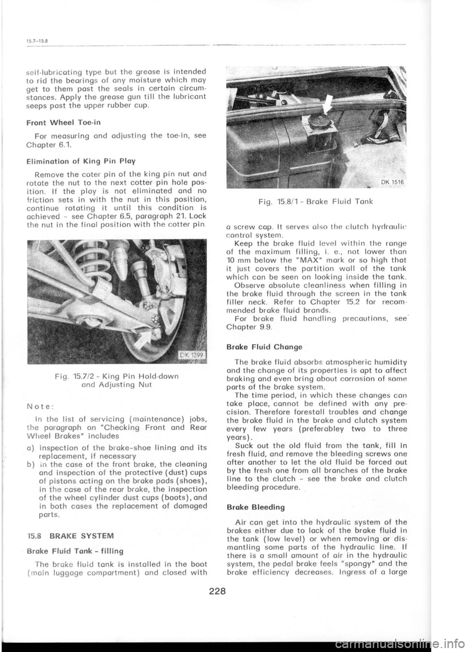
Remove the coter pin
of the king pin
nut ond
rotote the nut to the next cotter pin
hole pos-
ition. lf the ploy
is not elinrinoted ond no
friction sets in with the nut in this position,
continue rototing it
until this condition is
ochieved -
see Chopter 6.5, porogroph 21. Lock
the nut in the f irrol position
with the cotter pin
Fig. 15.712 -
King Pin Hold-down
cnd Adjusting Ntit
Note: irr the list
of servicing (mointenonce)
iobs,
I,he porogroph on "Checking
Front ond Reor
Wlreel Brokes" includes
o) inspection of the broke-shoe lining ond its
replocement, if necessory
b) in the cose of the front broke, the cleoning
ond inspection of the protective (dust) cups
of pistons octing on the broke pods (shoes),
in the cose of the reor broke, the inspection
of the wheel cylinder dust cups (boots),
ond
in both coses the replocement of domoged
ports.
i5.8 BRAKE SYSTEM
Broke Fluid Tonlk -
filling
The brake f luid tonk is instolled in the boot
{inoin luggcrge comportment)
cnd closed with Fig.
15.8/1 -
Broke Fluid Tonk
o screw cop. lt serves
olso the r:lutclr lryrlrotrlic
control systenr. Keep the brqke fluid level withirr tlre ronge
of the moximum filling, i.
e., not lower
thon
10 mm below the "MAX"
mork or so high thot
it just
covers the pcrtition
woll of the tonk
which con be seen on looking inside the tonk.
Observe obsolute cleonliness when filling
in
the broke fluid through the screen in the tonk
filler neck. Refer to
Chopter 15.2 for recon'r.
mended broke fluid bronds. For broke fluid hondlinq precoutions, see
Chopter 9.9.
Brqke Fluid Chonge
The broke f luid obsorbs otmospheric humidity
ond the chcnge of its properties
is opt to offect
broking ond even bring obout corrosion of some
ports of the broke system.
The time period,
in which these chonges
con
toke ploce,
connot be defined with ony pre-
cision. Therefore forestoll troubles ond chonge
the broke fluid in the broke ond clutch system
every few yeors (preferobley
two to three
yeors ) .
Suck out the old f
luid from
the tonk, fill in
fresh fluid, ond remove the bleeding screws
one
ofter onother to let the old fluid be forced out
by the fresh
one from oll bronches of the broke
line to the clutch -
see the broke ond clutch
bleeding procedure.
Broke Bleeding Air con get
into the hydroulic system
of the
brokes either due to lock
of the broke fluid in
the tonk (low
level) or when removing
or dis-
montling some ports
of the hydroulic line. lf
there is o smoll omount of oir in the hydroulic
system, the pedol broke feels "spongy"
ond the
broke efficiency decreoses. Ingress of o lorge
228