Page 472 of 537

Operation
of
the
heater
is
control
led
by
two
control
levers
located
on
the
instrument
panel
and
a
hand
op
erated
knob
on
the
center
of
the
heater
unit
The
AIR
LEVER
controls
the
air
intake
valve
and
or
room
valve
by
its
lever
positions
OFF
DEFROST
and
ROOM
through
the
control
cables
The
air
intake
valve
draws
the
fresh
outside
air
from
the
cowl
top
grille
and
supplies
the
air
into
the
heater
unit
The
room
valve
is
located
at
the
bottom
of
the
heater
unit
The
air
coming
through
the
air
intake
valve
opening
is
forced
through
the
heater
core
to
the
room
valve
where
the
air
is
distributed
to
the
floor
outlet
and
or
defroster
outlets
depending
on
the
position
of
the
room
valve
The
VENT
KNOB
is
directly
linked
to
the
vent
valve
which
provides
fresh
air
for
the
passenger
Push
the
knob
all
the
way
in
to
open
the
valve
The
fresh
ventilating
air
comes
out
of
the
heater
center
outlet
The
TEMP
lever
is
a
dual
pur
pose
control
one
is
for
regulating
the
flow
of
engine
coolant
flowing
into
Body
Electrical
System
the
heater
unit
and
the
other
for
the
operation
of
the
fan
motor
When
the
lever
is
in
the
OFF
position
the
water
cock
is
closed
and
the
circulation
of
engine
coolant
through
the
heater
core
stops
When
the
lever
is
slided
to
any
other
position
than
OFF
the
water
cock
opens
in
proportion
to
the
lever
setting
and
allow
engine
coolant
to
flow
into
heater
core
To
control
the
fan
motor
opera
tion
push
or
pull
the
lever
knob
Two
speeds
are
provided
for
the
fan
motor
by
using
a
three
position
switch
FUSE
IOfF
UlwlHI
ON
1
t
f
SWITCH
u
FUSI
BlE
rl
HEATE
R
LINK
SWITCH
is
G
luJ
BATTERY
HEATER
MOTOR
H
EATER
UN
IT
BE868A
Fig
BE
46
Circuit
diagram
of
heater
8E
27
Page 477 of 537
Body
Electrical
System
Circuit
diagram
of
seat
belt
warning
system
Non
California
modela
except
for
Canada
f
FUSIBLE
LINK
p
c
o
BATTERY
California
modela
f
Canada
modela
o
f
FUSIBLE
LINK
F
9
BATTERY
FUSIBLE
LINK
aP
c
BATTERY
IGNITION
SWITCH
FUSE
lOA
@
@I
TIMER
UNIT
I@
I
WARNING
fS
LAMP
l
2
IGNITION
RELAY
FUSE
1
lC
1
lOA
IGNITION
SWITCH
N
IGN
ITION
SWITCH
FUSE
lOA
BE
32
DRIVER
S
BELT
SWITCH
9
ORIVE
R
S
BELT
SWITCH
9
WARNING
r
i
LAMP
I
2
J
DRIVER
S
BELT
SWITCH
9
WARNING
fS
LAMP
I
2
J
Cf
BUZZER
BUZZER
BUZZER
BE689B
Fig
BE
56
Circuit
diagram
of
seat
belt
warning
system
Page 495 of 537
1
I
6
I
BA
RY
i
Air
Conditioning
BW
c
J
BW
n
B
m
00
L
ELECTRIC
FUEL
PUMP
oB
tl
b@
L
t
FROM
LIGHT
SWITCH
c
J
LW
2
L
rRL
fZP
W
I
FUSE
15A
J
D
CJ
B
1
COMPRESSOR
RELAY
B
GL
I
lL
GL1J
ILLUMINATION
CONTROL
RHEOSTAT
3
ILLUMINATION
LAMP
I
I
MAIN
RELAY
FAN
SWITCH
I
r
1
UE
H
I
I
THERMO
SWITCH
COLOR
CODE
@
IC
PRESSU
1
rlTCH
D
D
G
c
J
oc
I
m
f
F
I
C
D
SOLENOID
COMPRESSOR
FUSE
LR
I
BW
O
W
ov
J
I
IG
0
0
OVJ
AC
6
B
BW
L
LW
LR
W
G
GL
RL
Black
Black
with
white
stripe
Blue
Blue
with
white
stripe
Blue
with
red
stripe
White
Green
Green
with
blue
stripe
Red
with
blue
stripe
IG
BW
t
1
n
L
IGNITION
SWITCH
AC727
Fig
A
C
B
Wiring
diagram
of
air
conditioner
system
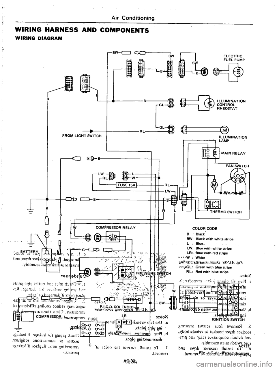
Page 519 of 537

Ll1
1t
W
l
THERMO
SWITCH
I
I
Air
Conditioning
WIRING
HARNESS
AND
COMPONENTS
WIRING
DIAGRAM
BW
c
J
ii
1
l
BW
La
GL
FROM
LIGHT
SWITCH
CJ
Id
lW
f
8
L
rRl
@
W
I
FUSE
15A
1
J
D
CJ
B
B
o
J
I
B
y
i
jqt
0
noc
I
no
vi
1
J
mcl
y
yldru
ao
11
jblr
J
H
WJ1
q
2f
br
r
t
lH
iot
f1
tH
o
hm
I
l
i
I
1
rf
l
t
f
r
dt
ll
II
h
J
IiJ
l
I
d
hi
s
n
Jq
DDj
G
w
TG
r
i
i
It
U
JI1
GH
Jdf
J
t
ggo
J
10
lHohfth
gniJuo
lUb
Jl
VUlt
l0
H
2
1
19
i
tl
b
wt
IO
t
l
lo
J
I
l
l
to
tJ
b
YR
lStO
Y1
1
t
J
I
FUSE
I
II
nlWI
I
bn
f
w
1
U
QI
llnio
fiq
ni
I
tsH
W
tflt
fli
htTin
lnl
O
J
11
IJ
i
Ji
fjI
i
i
11
i
ltll
ii
A
jll
I
I
I
gm
J
lIno
tl
Jl
JIIgiJ
l
1I0U
mflu
J
l
tllU
lJU
8
f
r
j
d
j
J
l1
Jlt
d
HInO
IG
to
l
VFJ
r1
rjJ
1
J
h
nI
0
i
IEvUID
l
il
1
i2
1
MN
k
B
gg
liii
gg
1
B
J
Ii
i
ELECTRIC
FUEL
PUMP
@
ILLUMINATION
CONTROL
RHEOSTAT
COLOR
CODE
B
Black
BW
Black
with
white
stripe
L
Blue
LW
Blue
with
white
stripe
LR
Blue
with
red
stripe
W
White
tll
G
GreeMnQ
r
iC
O
1
r
J
l
GL
Green
with
blue
stripe
R
L
Red
ith
blue
stripe
201011
lIt
J
m
I
W
tfli
I
o
lUll
IJ
Ub
OW
If
U
d
l
Q
I
ni
IGNITION
SWITCH
WIJIJJOO
W
l
Iuul
vomo
C
held
l
Jlb
vi
ia
1
1
tnd
15
W
le
llt
J
l
nq
LnJ
J
I
1
luil
mpHO
ibGt
L
D
lb
tldmoGl
nG
III
rbliw7
tHO
b
b
1
AC727
ns
1
j
fJ
l
YI
l
mtl
m
0
I
lfi
IO
fI
l
jg
h5
4
MjVj
IJC
p
i
W
i
1q