1976 CHEVROLET VEGA brake
[x] Cancel search: brakePage 27 of 87
Downloaded from www.Manualslib.com manuals search engine Parking Brake
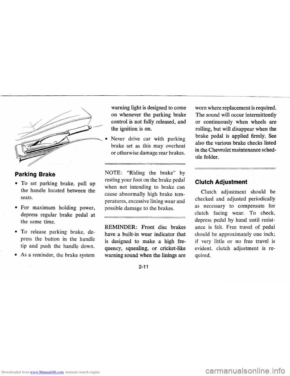
• To set parking brake, pull up
the handle located between the
seats.
• For maximum holding power,
depress regular brake pedal at
the same time.
• To release parking brake, de
press the button in the handle
tip and push the handle down.
• As a reminder, the brake system warning
light
is designed to come
on whenever the parking brake
control
is not fully released, and
the ignition ·
is on.
• Never drive car with parking
brake set
as this may overheat
or otherwise damage rear brakes.
NOTE: "Riding the brake" by
resting your foot on the brake pedal
when not intending to brake can
cause abnormally high brake tem
peratures, excessive lining wear and
possible damage to the brakes.
REMINDER:
Front disc brakes
have a built-in wear indicator that
is designed to make a high fre
quency, squealing,
or cricket-like
warning sound when the linings are
2-11
worn where replacement is required.
The sound will occur intermittently
or continuously when wheels are
rolling, but will disappear when the
brake pedal
is applied firmly. See
also the various brake checks listed
in the Chevrolet maintenance sched
ule folder.
Clutch Adjustment
Clutch adjustment should be
checked and adjusted periodically
as necessary to compensate for
clutch facing wear.
To check,
depress pedal by hand until resist
ance
is felt. Free travel of pedal
should be approximately one inch;
if very little
or no free travel is
evident , clutch adjustment is re
quired.
Page 28 of 87
Downloaded from www.Manualslib.com manuals search engine Self-Adjusting Brakes
• Brakes on this car (except for the
parking brake) are self-adjusting,
designed · to eliminate periodic
brake adjustments.
• Drum brake adjustment is made
automatically
as the brakes are
applied while car
is moving back
wards.
• Disc brake adjustment is made
automatically with each brake
application.
• If excess brake pedal travel devel
ops, drive alternately backward
and
forwb-d several times and apply
brakes firmly in eadh
direc
tion.
• See your dealer if normal pedal
travel
is not restored, or if there
is a rapid increase in pedal travel,
which could be a sign of other
brake trouble.
See your dealer
also if adjustment if the parking
brake
is required.
Headlight Beam Switch
"High" and "low" headlight
beams are controlled
by the floor
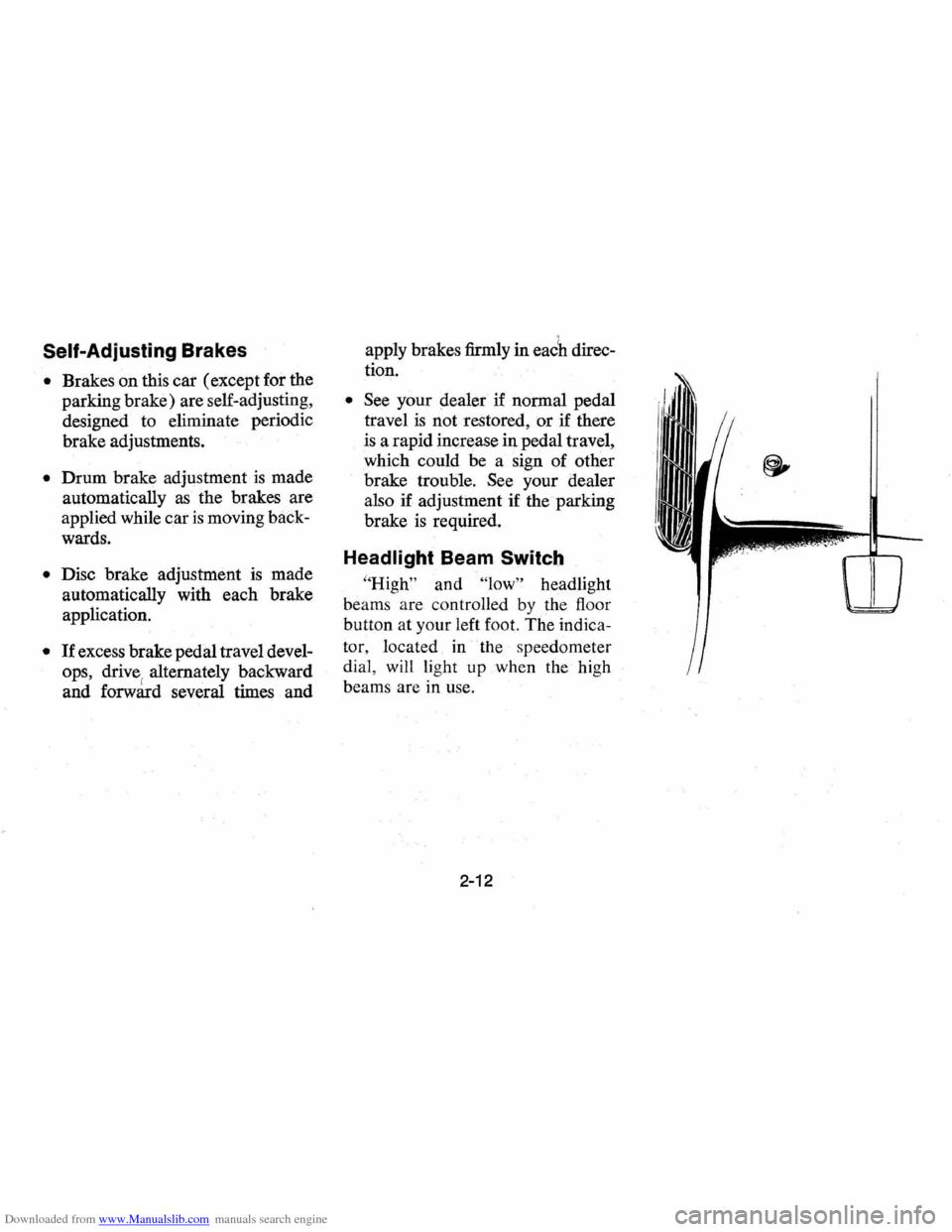
button at your left foot. The
indica
tor, located in the speedometer
dial , will light up when the high
beams are
in use.
2-12
Page 31 of 87
Downloaded from www.Manualslib.com manuals search engine Generator Indicator Light
The red light will go on when
the ignition key
is in the "on" posi
tion, but before the engine
is started.
After the engine starts, the light
should go out and remain out.
If
the light remains on when engine
is running, have your Authorized
Chevrolet Dealer locate and correct
the trouble
as soon as possible.
Temp. Pressure Indicator
Light
This indicator light is provided
in the instrument cluster to quickly
warn of an overheated engine
and/or extreme low oil pressure
or oil supply. This light will be on
when the ignition switch is turned
"ON" and should go out after the
engine
is started. Occasionally the
light may be seen to flicker momen
tarily, but this will do no harm. Ex
treme low oil pressure or oil supply
will prevent the electric fuel pump from
operating and under this con
dition the engine will not run.
If the light comes on during ex
treme driving conditions, such
as an
extended idle, turn off the air con
ditioner (if used) and run the en
gine slightly faster than idle speed
with the transmission in
neutral
gear. If the light does not go off
within a short period of time (1-2
minutes), then turn the engine off
until the cause of
the overheating is
corrected. Glance at the instrument
cluster frequently
as you drive to
see if this light is on.
Add Coolant Indicator Light
This indicator light is provided to
warn of a low coolant condition in
the radiator.
If coolant level is low
the yellow
"Add Coolant" warning
light will glow. Coolant level in the
coolant recovery tank, and radiator,
should be checked at the first oppor
tunity.
If necessary add sufficient
2-15
coolant to both the radiator and
coolant recovery tank.
(See Service
and Maintenance, Section 5, for
proper procedure) .
If frequent
additions are required, see your
dealer for a complete cooling sys
tem check.
Brake System Warning
Light
The service brake system is a dual
system designed so that one part will
provide some braking action in the
event of loss of hydraulic pressure
in the other part of the system.
If the
warning light labeled
"Brake" lo
cated in the speedometer face comes
on and stays
on when the ignition is
on and after the brakes have been
firmly applied
it may indicate that
there
is a malfunction in one part of
the brake system.
• As a reminder, the light is de
signed to come
on with the park
ing brake applied and the igni
tion on.
Page 32 of 87
Downloaded from www.Manualslib.com manuals search engine • The light is also designed to come
on during engine starting to
verify that the bulb
is operating
properly.
• Have system repaired if light does
not come
on during check.
• This warning light is not a substi
tute for the visual check of brake
fluid level required
as part of
normal maintenance.
If the light comes on:
• The parking brake control is not
fully released, or,
• The service brake system is par
tially inoperative.
What to do:
1. Check that parking brake is re
leased.
If it is . . .
2.
Pull off the road and stop, care
fully-remembering that:
• Stopping distances may be
greater.
• Greater pedal effort may be re
quired.
• Pedal travel may be greater. 3.
Try out brake operation by start
ing and s,topping on road shoul
der-then:
• If you judge such operation to
be safe, proceed cautiously at
a safe speed to nearest dealer
for repair.
• Or have car towed to dealer for
repair.
Continued operation of the car in this
condition
is dangerous.
Headlight Beam Indicator
Light
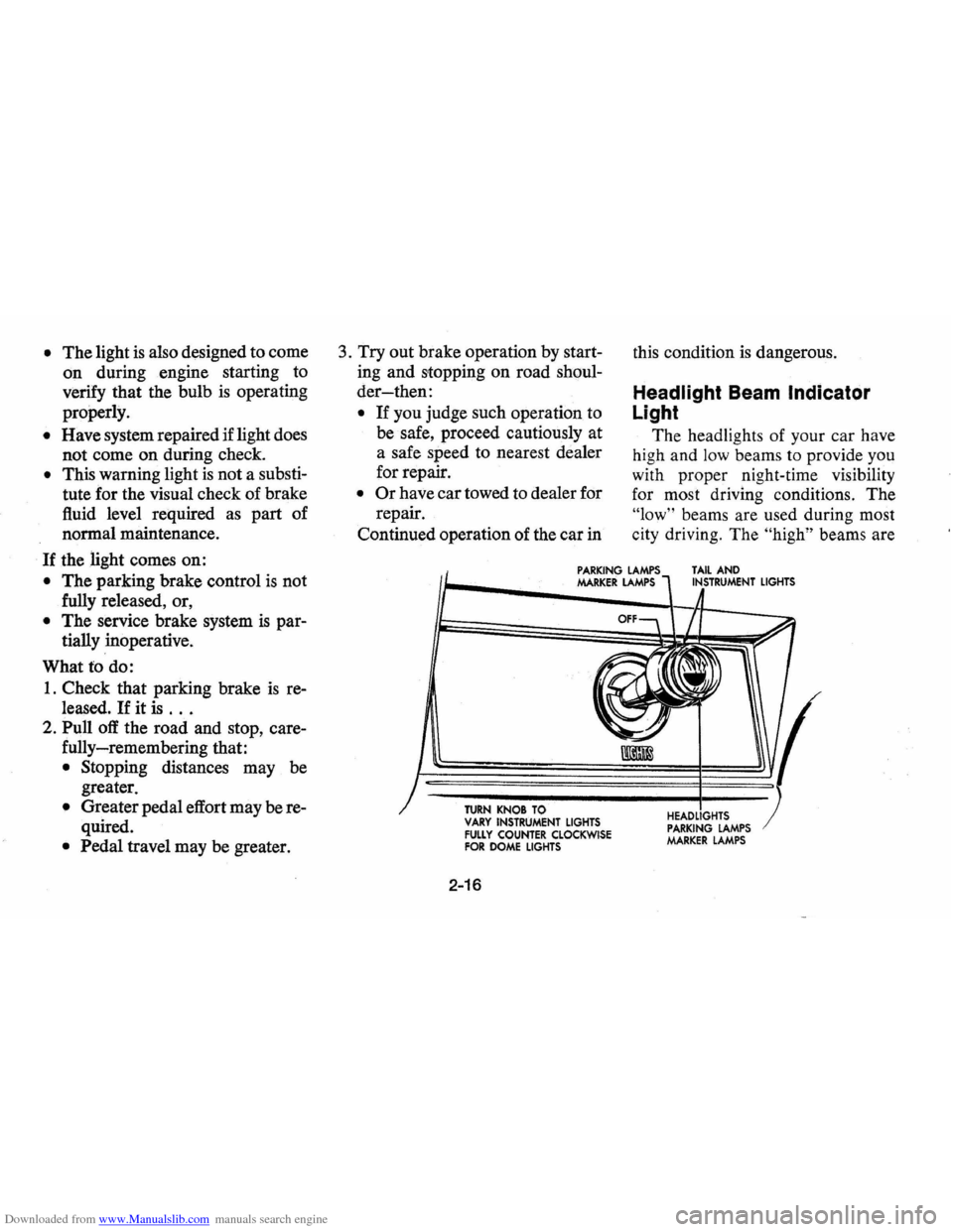
The headlights of your car have
high and
low beams to provide you
with proper night-time visibility
for most driving conditions. The
"low" beams are used during most
city driving. The
"high" beams are
PARKING LAMPS MARKER LAMPS TAIL AND INSTRUMENT LIGHTS
TURN KNOB TO VARY INSTRUMENT LIGHTS FULLY COUNTER CLOCKWISE FOR DOME LIGHTS
2-16
HEADLIGHTS PARKING LAMPS MARKER LAMPS
Page 46 of 87
Downloaded from www.Manualslib.com manuals search engine In Case of Emergency
Four Way Hazard
Warning
Flasher
• Use the warning flasher to warn
other drivers any time your
ve
hicle becomes a traffic hazard,
day or night.
• A void stopping on the roadway
if possible.
• Turn on the hazard warning
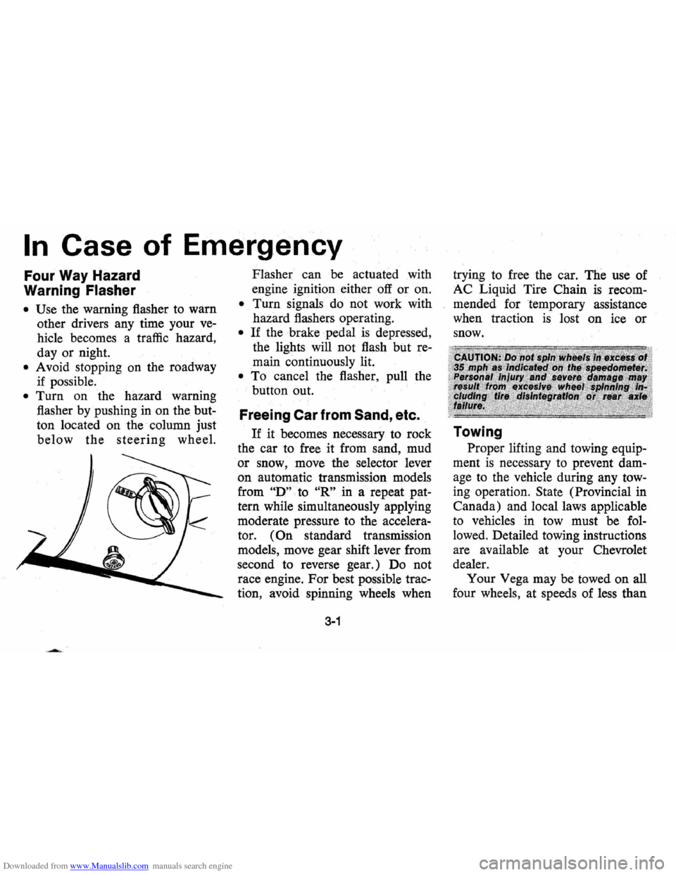
flasher by pushing
in on the but
ton located on the column just
below the steering wheel. Flasher
can
be actuated with
engine ignition either
off or on.
• Turn signals do not work with
hazard flashers operating.
• If the brake pedal is depressed,
the lights will not flash but
re
main continuously lit.
• To cancel the flasher, pull the
button out.
Freeing Car from Sand, etc.
If it becomes necessary to rock
the car to free it from sand, mud
or snow, move the selector lever
on automatic transmission models
from
"D" to "R" in a repeat pat
tern while simultaneously applying
moderate pressure
to the accelera
tor.
(On standard transmission
models, move gear shift lever from
second to reverse gear.) Do not
race engine. For best possible trac
tion, avoid· spinning wheels when
3-1
trying to free the car. The use of
AC Liquid Tire Chain
is recom
mended for temporary assistance
when traction
is lost on ice or
snow.
Towing
Proper lifting and towing equip
ment
is necessary to prevent dam
age to the vehicle during any tow
ing operation. State (Provincial in
Canada) and local laws applicable
to vehicles in tow must be
fol
lowed. Detailed towing instructions
are available at your Chevrolet
dealer. Your Vega may be towed on
all
four wheels, at speeds of less · than
Page 47 of 87
Downloaded from www.Manualslib.com manuals search engine 35 mph, for distances up to 50
miles, provided the driveline, axle,
transmission, and steering system
are otherwise normally operable.
Use only towing equipment specifi
cally designed for
this purpose
following the instructions of the
towing equipment manufacturer.
A separate safety chain system
must
be used for such towing and
steering must be unlocked, trans
mission in neutral and the parking
brake released. Attachments must
be made to main structural mem
bers of the car. Do not attach to
bumpers or associated brackets.
Remember that power brake and
power steering assist will not be
available when engine
is inopera
tive.
Recreational Towing
Vega models with a manual 3-
or 4-speed transmission may be
towed (with propshaft installed) be-hind
another vehicle
as a "dinghy"
at freeway speeds if additional SAE
80
or SAE 90 Gear Lubricant is
added to the transmission. This can
be accomplished · by removing the
filler plug and installing a
900-;.2
inch pipe street elbow fitting and
adding one quart
(2 lbs.) of SAE
80
or 90 Gear Lubricant. Use the
filler plug to cap the elbow fitting.
The additional lubricant will have
no adverse affect to the transmis
sion during normal use of the
ve
hicle and may be left in the trans
mission.
EMERGENCY STARTING
A car with a discharged battery
may
be started by using energy
3-2
from a battery in another car
called "jump starting".
NOTICE: Do not push or tow this
vehicle
to start. Damage to the cata
lytic converter and/or to other parts
of the vehicle may result.
Jump Starting
Jump starting may be dangerous
and should
be attempted only if, the
following three conditions are met.
If they are not,we strongly recom
mend that you leave the starting to
a competent mechanic.
• The battery in the OTHER vehi
cle must
be 12 volt and nega
tively grounded,
like the one in
THIS car. (Check the other car's
owner's manual to
see if it is.)
• The battery in THIS car must be
equipped with flame arrestor
vents (like the original-equip
ment Delco Freedom battery)
Page 48 of 87
Downloaded from www.Manualslib.com manuals search engine or flame arrestor type filler/
vent caps.
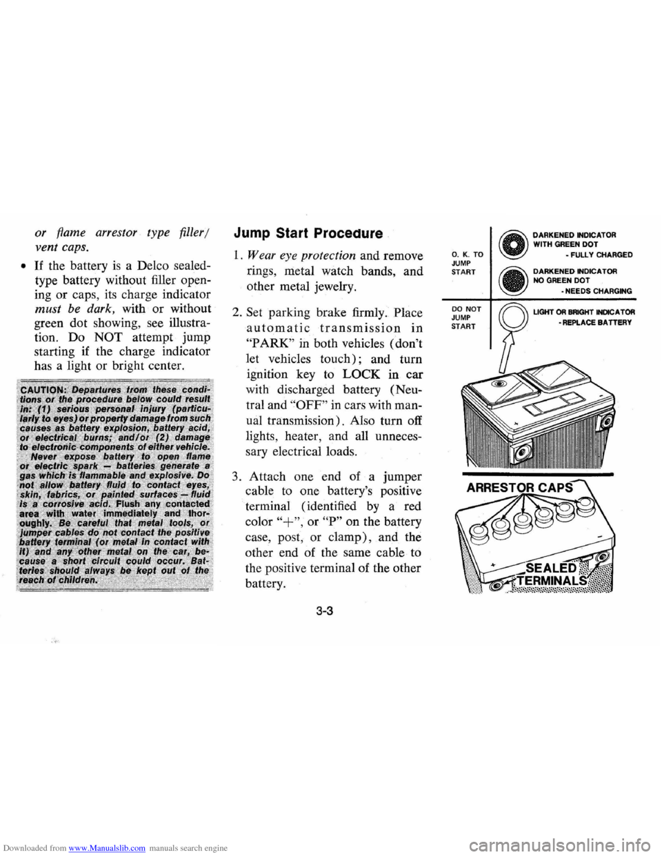
• If the battery is a Delco sealed
type battery without filler open
ing
or caps, its charge indicator
must be dark, with or without
green dot showing, see illustra
tion. Do
NOT attempt jump
starting if the charge indicator
has a light or bright center.
Jump Start Procedure
1. Wear eye protection and remove
rings, metal
watch bands, and
other metal jewelry.
2. Set parking brake firmly. Place
automatic transmission in
"P ARK" in both vehicles (don't
let vehicles
touch); and turn
ignition key to
LOCK in car
with discharged battery (Neu
tral and
"OFF" in cars with man
ual transmission). Also turn off
lights, heater, and all unneces
sary electrical loads.
3. Attach one end of a jumper
cable to one battery's positive
terminal (identified
by a· red
color
"+", or "P" on the battery
case , post , or
clamp), and the
other end of the same cable to
the positive terminal of the other
battery.
3-3
O. K . TO JUMP START
DO NOT JUMP START
o DARKENED INDICATOR
WITH GREEN DOT - FULLY CHARGED
• DARKENED INDICATOR
NO GREEN DOT
-NEEDS CHARGING
LIGHT
OR BRIGHT INDICA TOR -REPLACE BA TTERY
Page 49 of 87
Downloaded from www.Manualslib.com manuals search engine 4. Attach the remammg jumper Engine Coolant
cable FIRST to the negative ter
minal (black color,
"-" or "N")
of the OTHER vehicle's battery,
(regardless of which vehicle has
the discharged
battery) and
THEN to the negative terminal
of the battery in THIS
car-thus
taking advantage of the flame
arrestor feature on the battery in
THIS car, should a spark occur.
5. Start engine in the vehicle that is
providing the jump start (if it
was not running). Let run a few
minutes, then start the engine in Jacking Instructions
the car that has the discharged
battery.
6. Reverse the above sequence
EXACTL Y when removing the
jumper cables, taking care to re
move the cable from
[he negative
terminal of the battery in THIS
car
as the FIRST step.
3-4
Preparation
• Park on level surface and set
parking brake firmly.
• Set automatic transmission in
park (manual transmission in
reverse).
• Activate hazard warning flasher.
Instructions
1. After removing spare wheel
and tire, jack, jack base, and
jack handle (wheel nut
wrench), proceed with chang
ing the wheel
as follows:
2. Remove hub cap or wheel
cover with flat end of wheel
nut wrench and loosen, but do
not remove nuts, by turning
counterclockwise.
3. With column assembly seated
in base and lever in
"UP" posi
tion, insert jack hook in bum
per slot.
4. Base must sit flat with top of
column angled slightly away
from vehicle,
as shown in illus
tration.
5. Always operate jack with slow