1976 CHEVROLET MONTE CARLO air condition
[x] Cancel search: air conditionPage 15 of 102
Downloaded from www.Manualslib.com manuals search engine STARTING· AND OPERATING
Engine Exhaust Gas Caution (Carbon Monoxide)
Avoid Inhaling exhaust gases because
thay cont./n carbon mODOxlde, which by
1t'811 Is color/e.. and odor/elS. Carbon
monoxIde Is • dangerous gas fh,t can
caus. uneonsC /ousnftu and Is potentially
lelha/.
It at any time you .,u.pect that exhaust _
tumes ., •• nf.rlng'··the passenger com
partment , half' the -cause determined and
co".cfed a. soon as possible. II you must
drlv. under these c6ndltions, drive only
with a/l window. luliy open.
-
The best protection .gainst carbon mon
oxide entry Into the' C81 body Is a properly
maintained' engine exhaust system, car
body and body v.ntllallon syslem. /I Is
recommended tha' the -exhaust system
and body bo Inspecled by a compel"",
mechanic. .
• Each limo rhe vehlcl. I. ralsod lor 011
c"'ng8.
• Whn.If.r " change Is noticed in the
sound 01 IIH1 exhaul' sy~.m.
• Whene"., the ."haust system" 'under
body or TNr ot the .,ehlele is damaged.
S .. 1.0U1 Maintenance Schedule tolder
furn
shed with your .,ehle/. for Inspec
tion procedure .
To allow proper operation ot the car's
ventli.t/on system. keep tront ventilation
Inl.t grme e/hr at .now. I."ves or other
obstruction
.t .11 time,.
SITTING IN A PARKED CAR WITH
ENGINE RUNNING FOR
AN EXTENDED
PERIOD IS NOT RECOMMENDED.
Do not run ,.nglne In confined areas
such as ,garage. ",.iny more than needed
to mOlfe"vehic/. In' or' out of are •. When
v.hlc/ol • • 'opped In an UNCONFINED
ar •• with the engine running tor any more
than a 'short period , adJust he.ting or
cooling sy.tem to toree outside aIr into
car .s tollow,:
1. On cars not equipped with air condi
tioning.
set tan to medium or high
spefKi and upper control lever to any
poslUon oxcepl OFF.
2-1
2. ' On c." equipped with menu.' air call
dltlonlng, 8.t fIn to m.dium or high
speed. upper control lever to any pos;
: tlon except OFF, Ind lower contrOl
I.ver to Iny position except .xtrem •
. ,." COLD.
3. On cara equIpped with automatic a"
conditioning , .et control ,-.,e, to HI
except In hot wNther In .""lch cas.,
set lever In AUTO.
The Irunk lid should be closed while
driving to help prevent Inadvertently draw
Ing exhaust gases Into the car. It I. unwise
to drive .t high speed. for long dUrations
with
the trunk lid open. However, if for
some ,e.son the trunk must remain open
tor a period' whJle moving, or electrical
wiring
or other cabl. connections to a
trailer mu.t PlIS through the seal be
tween trunk lid and bo,dy, the following
precaut~ons shoUld be observed:
• Close all windows.
• Ad/u.t h •• tlng or cooling system to
force outside aIr Into car as described
In nem. 1, 2 and 3 abo,.e but with f.n
.al ., hIgh speod.
• On cats equipped with outside air vents
In or under Instrument panel, open
vonl. lully.
Page 24 of 102
Downloaded from www.Manualslib.com manuals search engine INSTRUMENT PANEL AND CONTROLS
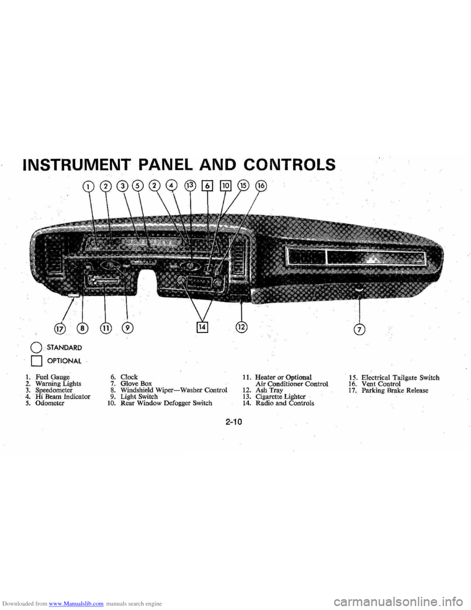
o STANDARD
o OPTIONAL
1. Fuel Gauge 2. Warning Lighls 3. Speedometer 4. Hi Beam Indicator 5. Odometer
6. Clock 7. Glove Box 8. Windshield Wiper-Washer COntrol 9. Light Switch to. Rear Window Defogger Switch
11. Heater or Optional
Air Conditioner Control
12. Ash Tray 13. Cigarette Lighter 14. Radio and Controls 1
5 . Electrical Tailgate Switch
16. Vent Control 17. Paridng Brake Release
2-10
Page 26 of 102
Downloaded from www.Manualslib.com manuals search engine ble'can be located and corrected .
. Driying the car with low oil pillS'
sure can:cause · serious ' engine
damage.
Genera~orlndicator Light
The red light will go on when
the
ignition key is in the "on " posi,
tion, b~f before the engine is
started.'J\fter the engine starts, the
light .
sho'uld go out and remain out.
If the Hght remains on when engine
is runlling, have your Authorized
Chevrolet Dealer locate and cor,
reCI the trouble as soon as possible,
Engine Temperature
Indicator Light
, This indicator light is provided
in the instrument cluster to quickly
warn
of an overheated engine. With
the ignition switch in the
5T AR T
position, the red TEMP indicator
will light to let you know that it is
operating properly. When
the engine
is started , the
red light will go out immediately,
It will light up at no other time
unless for some reason the engine
.
reaches a dangerously high oper,
atingtemperature. If the light
comes on during
extreme driving
conditions, such
as an extended
idle, turn
off the air conditioner (if
used }.and run the engine slightly
faster than
idle. speed with the
transmission in neutral gear .
If the
light does not go
off within a short
period of time
(F2 minutes), then
tum the engine off until the cause
of the.
overheating is corrected;
Glance at the
Ins.trument cluster
frequently as you drive to see if
this light
is on. '
Brake System Warning
Light
.
The service .. brake system is a
dual system designed
so that. one
part will provide some braking
2-12
action in the event of loss of hy'
draulic pressure in the other part of
the system.
If the ,warning light
labeled
"BRAKE," located in the
speedometer face, comes on .and
stays on when the ignition
is on and
'after · the brakes have been firmly
applied, it may indicate that
there
is a malfunction in one part of the
brake system.
'
•
As ~ reminde;, the light is de,
signed:to
come on with the park,
ing brake applied and the ignition
on.
• The light is also designed to
come on, during ;engine starting
to verify that the bulb is operating
. properly.
• Have system repaired '. if light
does not come
on' during check.
• This warning light, is not a sub
stitute for the visual check of
brake fluid level required
as part
of normal maintenance.
Page 27 of 102
Downloaded from www.Manualslib.com manuals search engine If the light comes oQ:
• The :parking brake control is not
fully
relea sed or, ,,:
• The service brake system is
partially inoperative .
What to do :
1. Check that the parking brake
is released. If it is ...
2.
Pull off the road and stop, care
fully-remembering that:
'
•
Stoppin g "distances may be
greater. ' '0:
• Greater pMal effort may be
required .: ;
• Pedal
travel may be greater.
3. Try out b~ake operati on by start
ing and
stopping on road shoul
der-then :
• If you judge such operation to
be safe , proceed cautiously at
a safe speed to neare st dealer
for repair.
• Or have car towed to dealer
}or repair .
Continued operation ' of the car in '
this condition
is dangerous.
Headlight High Beam
Indicator Light
The headlights of your ' car have '
high and
low, beams to provi(je you
with proper night-time visibility
for most . driving
conditioQs. The
"low" beams are used during most
city driving. The
"high" beams are
especially useful when
drh;ing on
dark roads since
they provide ex
cellent long range illumination.
The headlight beam
indicator will
be on whenever the high beams or
"brights" are in use. The Headlight
Beam
Switch controls the headlight
beams (see
Page 2-9).
Light Switch
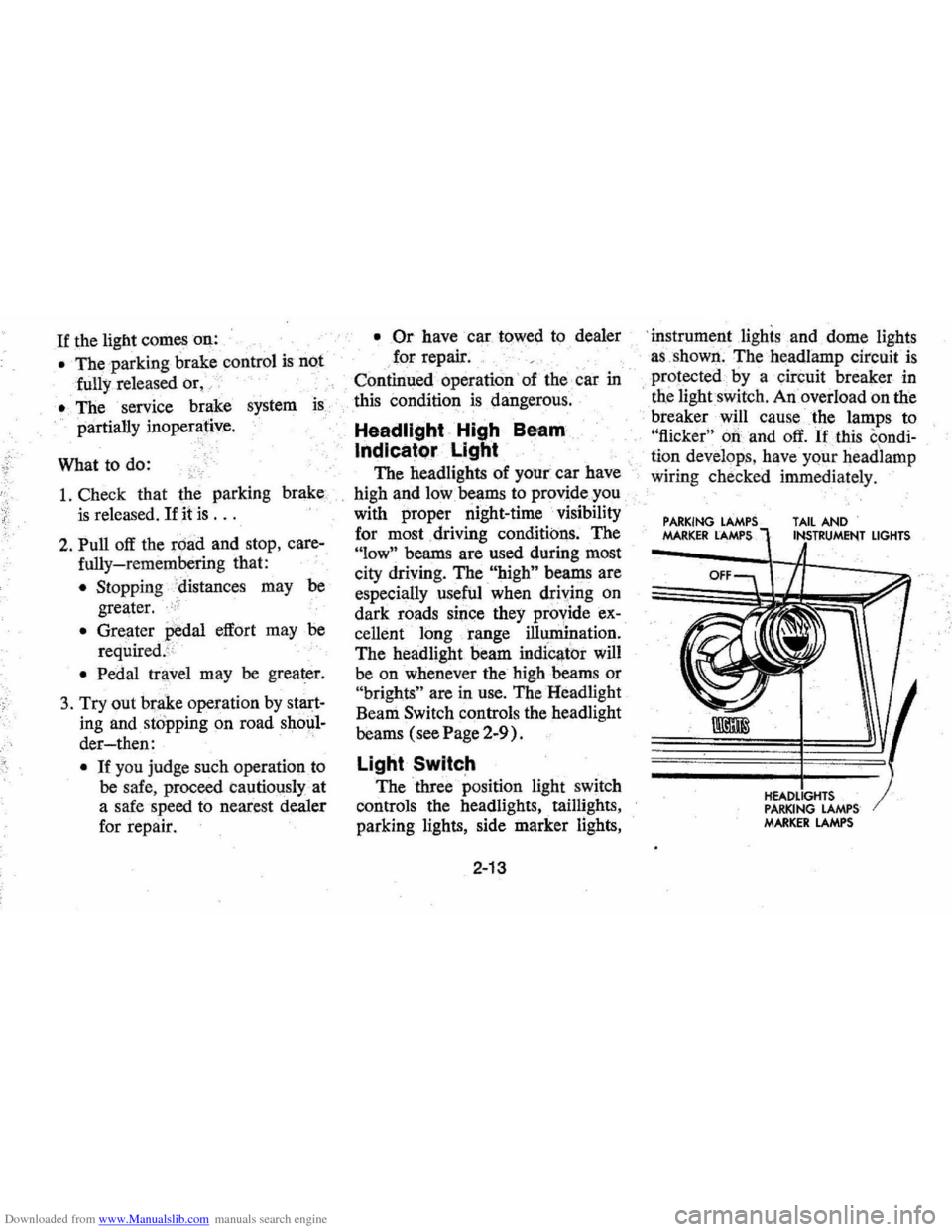
The three position light switch
controls the headlights " taillights,
parking lights, side marker lights,
2-13
'i nstrument lighis and dome lights
a s ,shown . The headlamp circuit
is
protected·· by a circuit breaker in
, tne lightswit ch . An overload on the
breaker will cause the lamps to
"flicker" 00 and off. If this condi
ti on develop s, hav e your headlamp
wiring check ed immedi ately.
PARKING MARKER LAMPS TAIL AND
PARKING LAMPS MARKER LAMPS
LIGHTS
Page 28 of 102
Downloaded from www.Manualslib.com manuals search engine NAL INSTRUMENTS AND 'GAUGES
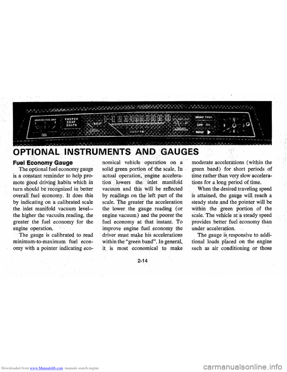
j:;".,nn,mv Gauge
The.optional fuel economy gauge
is a co~stant reminder to help pro
mote ' g~od driving . habits which in
turn should be recognized in better
overalfJuel economy, It does this
by
indicatingon a calibrated scale
the inlet manifold vacuum
level
the higher the vacuum reading, the
greater the fuel economy for the
engine
operation,
The gauge is calibrated to read
minimum -to-maximum fuel
econ
omy with a pointer iudicating eeo-
nomical· vehicle operation on a
solid green portion of the
scale, In
actual operation, )mgiue accelera
tionlowers the " inlet manifold
vacuum and this
will be reflected
by
r~~qings on tbe 'left part of the
scale, The greater" the acceleration
the lower . the gauge
readil1g (or
engine vacuum) and the poorer the
fuel
eeonomyat that instant. To
improve engine fueleconol)lY the
driver must make his accelerations
within
the "green band". In general ,
it
is most economical to make
2-14
moderate accelen'ltions (within the
green band) for short periods of
time rather
thanv«ry slow accelera
tions for along period of time.
When
the desired traveling speed
is attained, the gauge will. reach a
steady state
'.l1-nd the ,pointer will be
within the green portion of the
scale. The vehicle at
'a steady speed
providesbetterfuel.economy than
under acceleration. '
The gauge
is, responsive to addi
tional loads placed on the engine
such
as air conditioning or those
Page 32 of 102
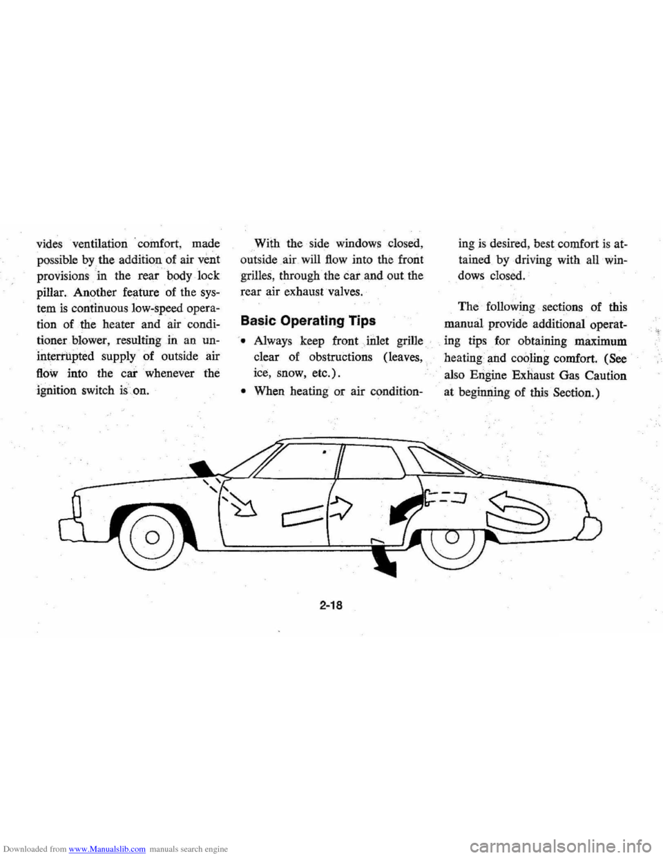
Downloaded from www.Manualslib.com manuals search engine vides ventilation . coillfort , made
possible
by the additionaf air veilt
provisions ' in the rear 1:>ody lock
pillar. Another feature of the
sys
tem is continuous low:speed opera
tion of the heater and air condi
tioner blower , resulting in an un
interrupted
supply of outside air
flOw into the car whenever the
ignition switch is.on. With
the side windows closed,
out side air will
flow into the front
grilles, through the car and out the
rear air exhaust valves.
Basic Operating Tips
'. Always keep front Jnlet grille
clear of obstructions (leaves,
ice, snow, etc.).
• When heating or air condition-
2-18
ingis desired , best comfort is at
tained by driving with all win
dows closed.
The following sections of this
manual provide additional operat-
. ing tips for obtaining maximum
heating and
cooling comfort. (See
also Engine Exnaust Gas Caution
at beginning of
this Seotion.)
Page 33 of 102
Downloaded from www.Manualslib.com manuals search engine Heater
The defrosting and
defogging
systenl assists in provid,
ing good visibility through desig
nated areas of the windshield under
most
inClement'Weather conditions.
For immediate operation of the ve
hicle, the windshield should be
scraped clear.
'
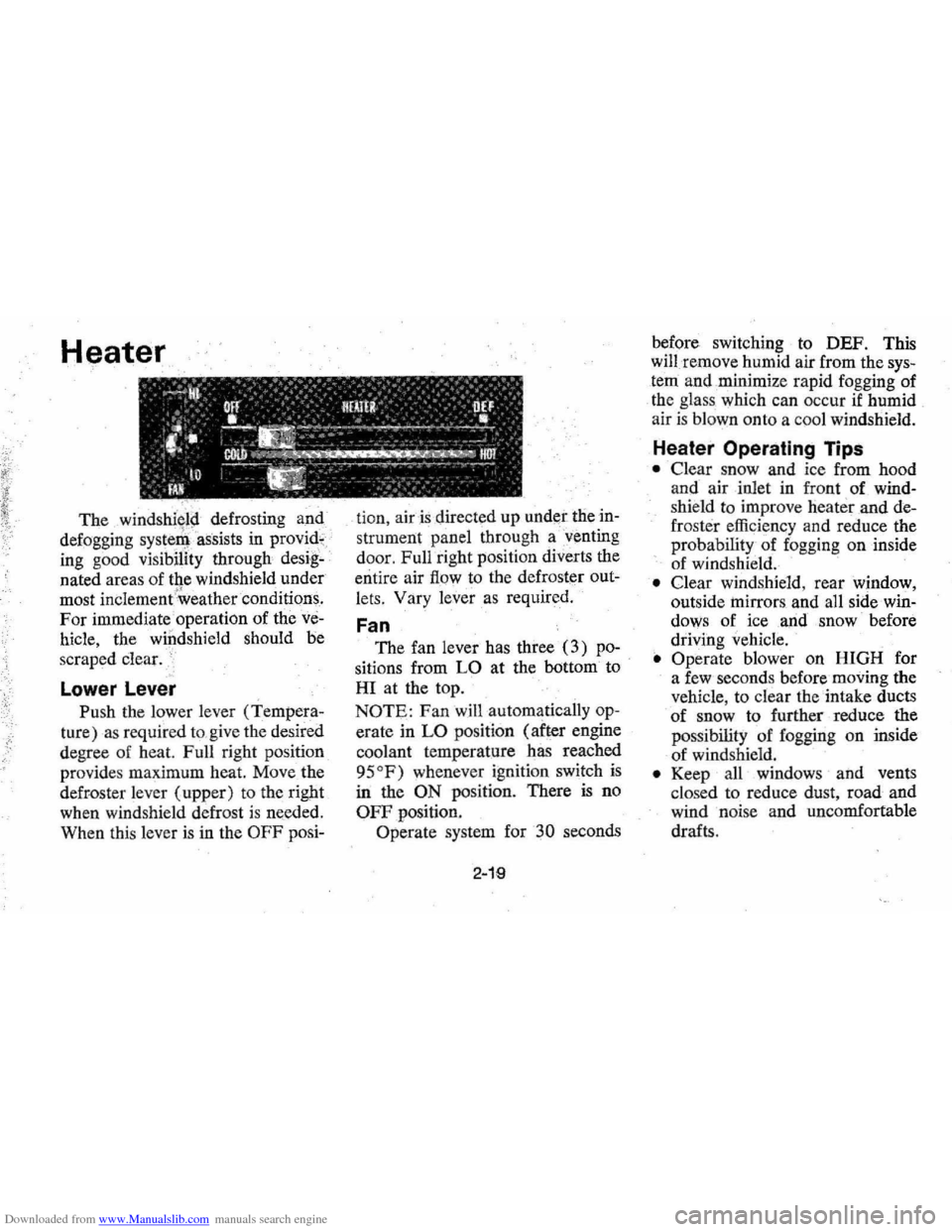
Lower Lever
Push the lower lever (Tempera
ture) as required to,give the desired
degree of heat. Full right position
provides maximum heat.
Move the
defroster lever (upper) to the right
when windshield defrost
is needed.
When this lever
is in the OFF posi- tion,
air is directed
up under the in
strument panel through a'venting
door, Full right position diverts the
entire air
flow to the defroster out
lets, Vary
lever as required.
Fan
The fan lever has three (3) po
sitions from LO at the bottom to
HI at the top.
NOTE: Fan will automatically op
erate in LO position (after engine
coolant temperature has reached
95
OF) whenever ignition switch is
in the ON position. There is no
OFF position.
Operate system for
30 seconds
2-19
before switching to DEF. This
will remove humid air from the
sys
tem and ,minimize rapid fogging of
the glass which can occur
if humid
air is blown onto a coo l windshield.
Heater Operating Tips
• Clear snow and ice from hood
and air inlet in front
of wind
shie ld to improve heater and de
frost er efficiency and reduce the
probability of fogging on inside
of windshield.
• Clear windshield, rear window,
outside
mirrors , and all side win
dows of ice ,and snow before
driving vehicle.
• Operate blower on HIGH for
a few seconds before moving the
vehicle, to clear the intake ducts
of snow to further reduce the
pos sibili
ty of fogging on inside
of windshield.
• Keep all windows and vents
clo sed to reduce dust, road and
wind noise and uncomfortable
drafts .
Page 34 of 102
Downloaded from www.Manualslib.com manuals search engine • For most satisfactory heater op
eration and air circulation , oper
ate fan on low or medium speeds
for normal operation and high
s peeds for quick warm -up and
during extremely low
tempera
tures.
• For adeq uate rear sea t he ating,
the area beneath the front seat
mus not be block ed by carpet
ing, rags, paper or oth er mate
rial and fan sh ould operate on
high blower.
Rear Window Defroster
To ensure clear vision through
the rear
window during inclem ent
weather , the Rear Window
De
froster is optionally available. This
unit dr
aws. in air from the pas
senger compart ment and directs it
aga inst the back window to remove
frost or moisture. Its blower h
as a
two-speed control switch on the
instrument panel.
Four Season Air Conditioning System
Operating instructions for your
Four Season Air Conditioner are
a s follows:
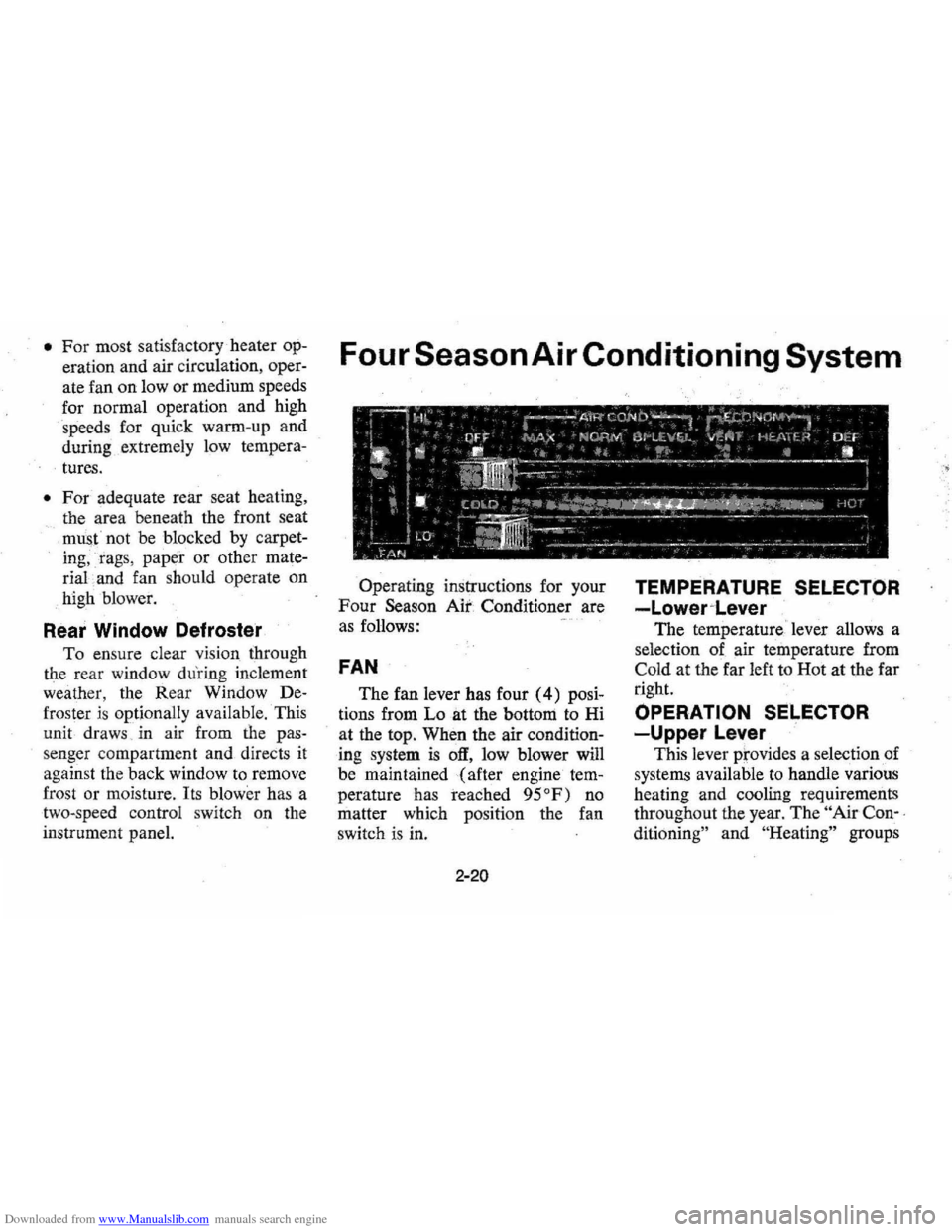
FAN
The fan lever has four (4) posi
tions from Lo at the bottom to Hi
at the top. When the air
condition
ing system is off, low blower will
be maintained (after engine
tem
perature has reached 95°F) no
matter which positi on the fan
switch is in.
2-20
TEMPERATURE SELECTOR
-Lower~Lever
The temperature ' lever allows a
selection of air temperature from
Cold at the far left to Hot at the far
right.
OPERATION SELECTOR
-Upper Lever
This lever prov ides a selection of
systems available to handle various
heating and cooling requirements
throughout the year.
The " Air Con-,
ditioning"
an d "He ating" groups