1976 CHEVROLET MONTE CARLO Brake
[x] Cancel search: BrakePage 24 of 102
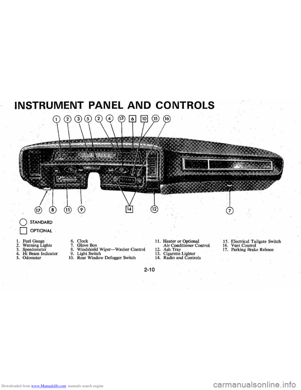
Downloaded from www.Manualslib.com manuals search engine INSTRUMENT PANEL AND CONTROLS
o STANDARD
o OPTIONAL
1. Fuel Gauge 2. Warning Lighls 3. Speedometer 4. Hi Beam Indicator 5. Odometer
6. Clock 7. Glove Box 8. Windshield Wiper-Washer COntrol 9. Light Switch to. Rear Window Defogger Switch
11. Heater or Optional
Air Conditioner Control
12. Ash Tray 13. Cigarette Lighter 14. Radio and Controls 1
5 . Electrical Tailgate Switch
16. Vent Control 17. Paridng Brake Release
2-10
Page 26 of 102
Downloaded from www.Manualslib.com manuals search engine ble'can be located and corrected .
. Driying the car with low oil pillS'
sure can:cause · serious ' engine
damage.
Genera~orlndicator Light
The red light will go on when
the
ignition key is in the "on " posi,
tion, b~f before the engine is
started.'J\fter the engine starts, the
light .
sho'uld go out and remain out.
If the Hght remains on when engine
is runlling, have your Authorized
Chevrolet Dealer locate and cor,
reCI the trouble as soon as possible,
Engine Temperature
Indicator Light
, This indicator light is provided
in the instrument cluster to quickly
warn
of an overheated engine. With
the ignition switch in the
5T AR T
position, the red TEMP indicator
will light to let you know that it is
operating properly. When
the engine
is started , the
red light will go out immediately,
It will light up at no other time
unless for some reason the engine
.
reaches a dangerously high oper,
atingtemperature. If the light
comes on during
extreme driving
conditions, such
as an extended
idle, turn
off the air conditioner (if
used }.and run the engine slightly
faster than
idle. speed with the
transmission in neutral gear .
If the
light does not go
off within a short
period of time
(F2 minutes), then
tum the engine off until the cause
of the.
overheating is corrected;
Glance at the
Ins.trument cluster
frequently as you drive to see if
this light
is on. '
Brake System Warning
Light
.
The service .. brake system is a
dual system designed
so that. one
part will provide some braking
2-12
action in the event of loss of hy'
draulic pressure in the other part of
the system.
If the ,warning light
labeled
"BRAKE," located in the
speedometer face, comes on .and
stays on when the ignition
is on and
'after · the brakes have been firmly
applied, it may indicate that
there
is a malfunction in one part of the
brake system.
'
•
As ~ reminde;, the light is de,
signed:to
come on with the park,
ing brake applied and the ignition
on.
• The light is also designed to
come on, during ;engine starting
to verify that the bulb is operating
. properly.
• Have system repaired '. if light
does not come
on' during check.
• This warning light, is not a sub
stitute for the visual check of
brake fluid level required
as part
of normal maintenance.
Page 27 of 102
Downloaded from www.Manualslib.com manuals search engine If the light comes oQ:
• The :parking brake control is not
fully
relea sed or, ,,:
• The service brake system is
partially inoperative .
What to do :
1. Check that the parking brake
is released. If it is ...
2.
Pull off the road and stop, care
fully-remembering that:
'
•
Stoppin g "distances may be
greater. ' '0:
• Greater pMal effort may be
required .: ;
• Pedal
travel may be greater.
3. Try out b~ake operati on by start
ing and
stopping on road shoul
der-then :
• If you judge such operation to
be safe , proceed cautiously at
a safe speed to neare st dealer
for repair.
• Or have car towed to dealer
}or repair .
Continued operation ' of the car in '
this condition
is dangerous.
Headlight High Beam
Indicator Light
The headlights of your ' car have '
high and
low, beams to provi(je you
with proper night-time visibility
for most . driving
conditioQs. The
"low" beams are used during most
city driving. The
"high" beams are
especially useful when
drh;ing on
dark roads since
they provide ex
cellent long range illumination.
The headlight beam
indicator will
be on whenever the high beams or
"brights" are in use. The Headlight
Beam
Switch controls the headlight
beams (see
Page 2-9).
Light Switch
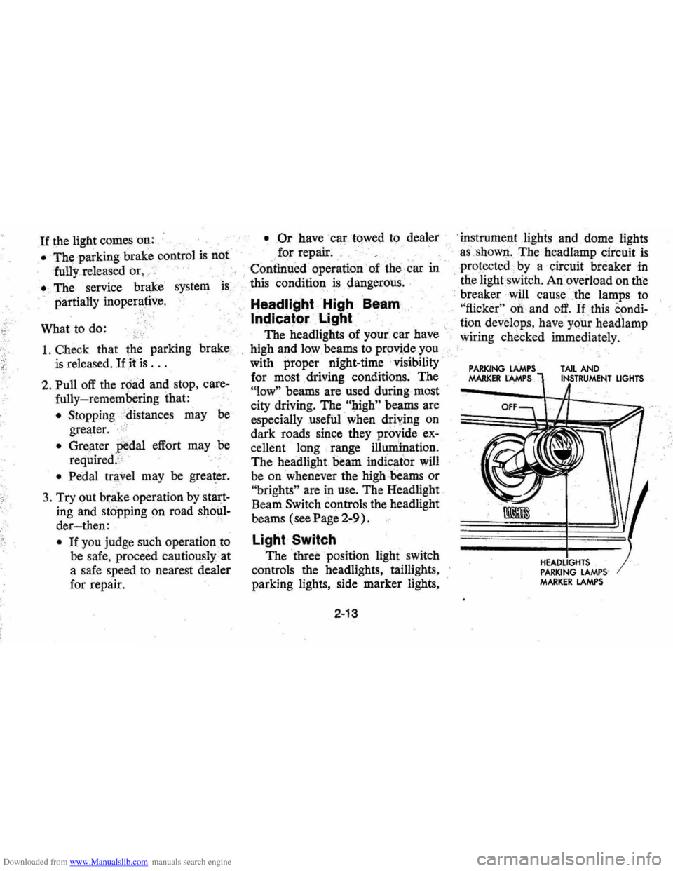
The three position light switch
controls the headlights " taillights,
parking lights, side marker lights,
2-13
'i nstrument lighis and dome lights
a s ,shown . The headlamp circuit
is
protected·· by a circuit breaker in
, tne lightswit ch . An overload on the
breaker will cause the lamps to
"flicker" 00 and off. If this condi
ti on develop s, hav e your headlamp
wiring check ed immedi ately.
PARKING MARKER LAMPS TAIL AND
PARKING LAMPS MARKER LAMPS
LIGHTS
Page 48 of 102

Downloaded from www.Manualslib.com manuals search engine l,nCase of Emergency '
Four Way Hazard
Warning Flasher
• Use the warningJlashe~ to warn
othe~ drivers allY time your ve
hicle becomes a traffic hazard,
day
ornight. ",
•
A void stopping on the roadway
if possible, .
.' Turn on the hazard warning
flasher
by pt\'shing in on the but,
ton located on the column just
below the steering
wheeL Flasher
can
be actuated with engine igni
tion either off
or on.
• Turn signals do not work with
hazard flashers operating.
• If the brake pedal is depfessed,
the lights will not flashbutre
main continuously lit
• To cancel the flasher, pull the
button out.
'':.',
Freeing Car From Sand; etc.
If it becomes 'neces sary to rock
the car to free it from sand, mud
or snow, move the selector lever
on automatic transmission models
from '~D" to "R" in a repeat pat
tern while simultaneously applying
moderate pressure to the accelera-
3-1
tor. Do not race engine. For best
possible traction, avoid spinning
wheels while
trying to free the car.
The use of AC Liquid Tire Chain
is recommended for temporary as
sistance when traction is lost on ice
or snow.
Towing
Proper lifting and towing equip
ment
is necessary to prevent dam
age to the vehicle during any
tow
ingoperation. State (Provincial in
Canada) and local
laws applicable
to vehicles in tow must be followed.
Detailed towing instructions are
available at your Chevrolet dealer.
Page 49 of 102
Downloaded from www.Manualslib.com manuals search engine Your Chevrolet may be towed
on all four wheels , at speeds of less
than
35 mph, for distances up to
50 miles, provided the driveline,
axle , tranSmission, and steering
sys
tem are otherwise normally oper
able.
Use only towing equipment
specifically designed for this
pur'
pose following the instructions of
the
towing equipment manufac
turer.A separllte safety chain sys
tem must be used. For such towing
the steeringi;Dust be unlocked,
' transmission in neutral
an~ the
parking brake released. Attach
ments must
oe made to mai!1 ,struc
tural members of the car. Do not
attach to bumpers or
,aSsociated
brackets. ' Remember that power
brake and power steering assists
will not be ,available when engine
is inoperative,
EMERGENCY STARTING
NOTE: Do not push or low this
vehicle to start. Damage to the cata
lytic converter and / or to other parts
of the vehicle may result.
• A car with a discharged 'battery
may be started by using energy
from a battery
in' another car
call<:!d "jump starting ".
Jump Starting
Jump starting may be dangerous
and should
be attempted only if the
followi!1g three , ,~onditions are met.
If they are not, we strongly,~ecom
mend that you leave the starting to
a competent mechanic.
• The battery in the OTHER vehi
cle must be
12 volt and negatively
3-2
grounded, like the, one in TillS
car. (Check the' other car's
owner's manual
to see if it is.)
• The battery in THIS car must be
equipped with
flame arrestor
type
filler / venl caps on all filler
openings (as
was the original
equipment
De ,lco battery), or it
, must be a sealed-type battery
which does not have
fi'tler open
ings or
caps, (Each Delco bat
tery flame arrestor cap has a grey
disc rather than a small hole-see
illustration. )
•. If thebatiery is a Delco sealed
type battery without filler open
ings or
caps"its charge indicator
must be dark, with or without
green dot showing, see illustra
tion. Do
NOT attempt jump start
ing
if the charge indicator has a
light or bright center.
Page 50 of 102

Downloaded from www.Manualslib.com manuals search engine 0: K.TO JUMP START
~ DARKENED INDICATOR WITH GREEN DOT .. . •• BATTERY CHARGE OK • FLUID LEVEL OK
Jump Start Procedure:
1. Wear eye protection and remove
rings, metal watch bands, and
other metal jewelry.
3-3
2. Set parl<;ing brake ,firmly. I'lace
automatic transmission in
"PARK" in both vehicles (don't
let
vehicles touch); turn ignition
key to LOCK in car with dis
charged battery (Neutral and
"OFF" in cars with,manual
transmissioJl). Also turn off
lights, heater,
ancl all unh~cessary
electrical loads.
3. Attach one end of a jumper
cable
to one battery's positive
terminal (identified
by a red
color, "+1', or "P" on the bat
tery case, post, or clamp), and
the other end
of the same cable
to the positive terminal of the
other battery.
Page 51 of 102

Downloaded from www.Manualslib.com manuals search engine 4. Attach the remaining jumper
cable
FIRST to the negative
terminal (black color,
"-", or)
"N") of the OTHER vehicle's
battery,
'. (regardless of which
vehicl~ 'has the dis!:harged bat
tery)
and THEN to the negative
tertniDal of the battery in TIllS
car-thus taking advantage of
the
J\ame arrestor feature on the
bat~ in TIllS car, should a
. spark occur .
5. St~the engine in the vehicle
that. is providing the jump start
(iOt was not running). Let run
a
few minutes , then start the en
gin~ in the car that has the dis
charged battery.
6. Reverse the above sequence
EXACTLY when removing the
jumper cables, taking care
to
remove the cable from the nega
tive terminal of the battery
in
THIS
car as the FIRSI' step.
Engine Coolant
'.,"
3-4
JACKING INSTRUCTIONS
Preparation
• Park on level surface and set
parkir)g brake firmly.
• Set automatic ,transmission in
park.
• Activatehazard",vaming flasher.
Instructions
1. After removing spare wheel and
tire, jack, jack
base, and jack
handle (wheel nut wrench), pro
ceed with changing the wheel
as follows: '
2 . When removing rear wheel,
re
move wheel opening cover (if so
Page 72 of 102
Downloaded from www.Manualslib.com manuals search engine Front Wheel Bearings
Every 30,000 miles-clean and
repack with
a. high melting point
wheel bearing lubricant.
Use wheel
bearing lubricant GM Part No.
1051344 or equivalent. This
is a
premium high
~elting point lubri
cant. When replacement is neces
sary specify Delco parts.
Brakes
Brake linings should be periodi
cally inspected for wear
by a quali
fied technician. The frequency of
this inspection depends upon
driv
ing conditions such as traffic or
terrain, and also the driving tech
niques of individual owners .. Your
Chevrolet Dealer is best qualified
to advise you
as to how often this
inspection should be performed.
When replacement is required,
specify
GM and Delco parts.
REMINDER: The front disc
brakes have a built-in wear indica
tor
thatis designed to make a high
frequency , squealing
or cricket-like
warning
sOl!l1d when the linings are
worn to where replacement is re
quired. The sound will occur inter
mittently or continuously when
wheels are rolling, but will
dis
appear when the brake pedal is
firmly applied. Also see the brake
checks listed. in the Maintenance
Schedule folder.
5-11
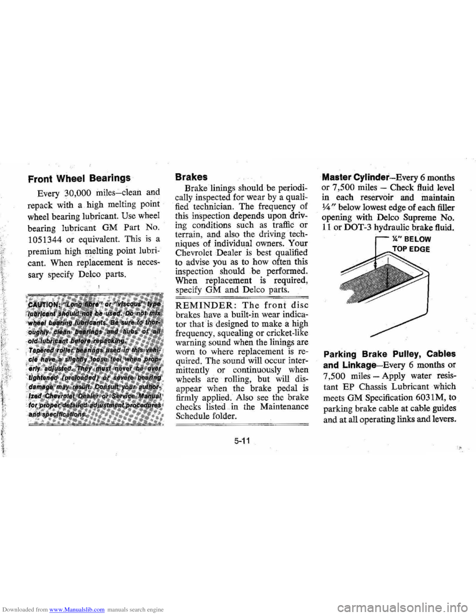
Master Cylinder-Every 6 months
or
7,500 miles -Check fluid level
in each reservoir and maintain
14" below lowest edge-of each filler
opening with Delco Supreme No.
liar DOT-3 hydraulic brake fluid.
11." BELOW
TOP EDGE .k:::O"',
Parking Brake Pulley, Cables
and Linkage-Every 6 months or
7
,500 miles -Apply water resis
tant EP Chassis Lubricant which
meets GM Specification 6031M, to
parking brake cahle at cable guides
and at all operating links and levers.