1974 FORD CAPRI engine
[x] Cancel search: enginePage 126 of 205
Chapter 6 Manual gearbox and automatic transmission 125
18 Carefully ~ove the lrilnsmission reilrwards ilnd downwmds, and
away from the car. Make sur e that lhe torque conver ter rema ins fully in
the transmission. 19 Refilling is the reverse of remova l but ensure that the torque converter drain plug is In line wIth the hole in the driveplate . To check
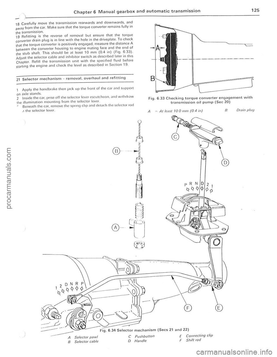
that the torque converter is positively engaged. measure the distance A between the converter housing to engine mJting fJce and the end of the $llIb ShilfL This should be al leilsl 10 mm (0.4 in) (Fig. 633). Adjust the selector cilble i1nd inhlbilOr switch i1S deSCribed later ill this Chapter. Reftll the 1riln smission unit with lhe specified flu,d before StDrlll1g the ennine i1nd check lhe level i1S describe(f in Section 19.
21 Selecto r mechililism -removnl. overhnlll ilud refitting
Apply the hnndbr,lke then Inek up the front of the car ilntl suppo'1
on ilxle stands. 2 Insi(fe the cm. prose off th e selector lever escutcheon. ,md wothrhaw
!he Illumillnt,on 1ll0U1l1l1l\J from the selec tor lever Oeneilth the CM. remove the Spr
r(
®---i
A
6 .33 Checking torque converter engagement with trnnsmission oil pump (Sec 20)
Alle,1S1 100111111 (0.4 ill) 8 O(.1ill (lluy
:-----
--
6 .34 Selector mechanism (Secs 2 1 and 22)
A SclcclOf pawl B SClccrof cabie
C Pusllbu/loll
o Natld/c
f Connccting clip F Shill (od
.'
. 1 , ;
I
procarmanuals.com
Page 128 of 205

Chapter 6 Manual gearbox and automatic transmissio n 127
2 Select position O' th en pri$e off the selector level escutcheon nnd. Irom under th e cnr. re move the plug in the side 01 the selector housing. 3 Adjust the inhibito r cnble locknut X to giv e a dimension of 0.1 to 0.2 mm (0.004 to 0 .008 in) (Fig. 6 .36). 4 Refit the plug nnd escutcheon. S With the trnn smission shih lever and the mnnunl selector lever in '0'. ndJust th e selector rod link until it cnll be reconnected without strain .
23 Downshift cable -removal. refitting and adjustment
Support till! front o f th e cm on Jxle Sl
24
S lnrter inhibitor/reverse Inml) switch -removal and re fitting
1 Pull the cable connector off the switch" 2 Unscrew the slnrter inhihitor swilch and remove the a"int[ 3 To rel'llhe swilCh. fil a new a·ring nnd screw the switch into lhe housing longer. tight. T'gh ten Ihe switch 10 the lorque wrench settin g
given ,n the Specilicntions. I t is imporlnl11 ,hn t thiS torque is not excee dud, 4 Ro::I't the cnhle plug conn ector to the sw,tch,
5 Chuc k th,ll th e en!J"'c will st",t only w,th the lever '" the '1" and "N' posilions and in no other POSlt'on. S TlIIn 0 " the ignition without startll1g th e engine, Check IhM the
r ' ;inU light comes 0 11 in th e "R" po~rtlon, but not in any other.
25 .tension housing o il senl-renew,,1
1 Remove the propeller shnl!. ns do::scrrhed III Chi,pter 7.
2 Jnck t he r enr of Ihe c,u to [1Hn",HSe the loss of 011 from the
transmission . then carefully pr ise out the od seill. being cJrtJIut not to (JamJ,Je the machined recess into which the sc,rI I,ts, 3 E'lslIfe that the recess is cle
6.37 Adjusting the downshift cable (Sec 23)
Depress Ihlollle hJlly (bloken arIOw). Pivol/he downshilllev,·( ,)wuy frum Ihe ,1ccelef,1{Qr sllMI lind UdjllS! Ih e clcarance at Ihe MljllSling nul (solid arrow)
~r:;0/,/5.;~··ll ~
Fig. 6,38 Inhibito r switc h renewal (Sec 24)
A Wiling connector B Inhibl/Ul swilch C O-riny
26 Fault dingl10sis -nutornatic Ir
"."
" , .
, ,
J
,
procarmanuals.com
Page 140 of 205
•
Chapter 8 Rear axle 139
ci,cumS«"Ulces mny only one pmt of the two be renewed. fnspect the dllfe,enti,ll pinions nnd side gems for signs of pitting. score mMks. Chipping nnd general wem. Obtain new gears as necessa,y . Inspect the th,ust washers lor signs of weM or deep sco,ing. Obwin new thrust wnshe,s as necessary. Once the pinion o il senl has been disturbed it must be discMded and a new one obtained. 20 When new pnrts have been obwined ns required. reassembly cnn begin. First lit the thrust washers to the side gems and place them in position in the differential housing. The ground side of the thrust washers IllUSt lace the side gC.Jrs. 21 Place tile thrust wilshers behind the dillelentini pinion genrs i1nd mesh these twO Oems with the Side gears through the tWI) ilpertores in the lilllerentlill housing. Milke sure they ilre diametlicilily opposite 10 each other. RO«l!e the clillerent'i11 pinion gears through 90' so brinUlI1\j them into line with the pinion genr shnlt bore 111 the housinlt 22 Insert the pinion genr shnft with the lock In!) p'n hole III line with the pill hole. 23 Usinu leeler 1),IU!Jcs. measure the en{lll(",t 01 ench s,de Be,,,. II the speclficd h\Jure IS excecrt"d. IU!W tl"u~t washlllS mu"t he olJt,uned
-omnlllie the a~~el)lhly ,lg,llll ,trld ht new thll,st wa:,lu'
28 Using soitable diameter tubes. fit the two Wper roller bearing cones into the finnl dlive housing. making sure that they ale litted the correct way round. 29 Slide the shim and spncer onlO the pinion shalt and insert inlo t he final drive housing. 30 Relit the second and smaller diameter wper loller bea,ino onto the end of the pinion shaft lind 101i0w Ihis Wilh a new oil seal. Sefore Ihe senl is nctually fitted. apply some grense to the inner Ince between the two lips of the seal. 31 Apply n little jOinting compoond to the outer Ince of the seD I. 32 Using n tuhulilr dllft 01 suitable dinmeter, carefully drive the oil seal into the fillal (hive housinlJ. Make quite sore thnt it is lilted squarely and flush with the housinU. 33 Refn the drive pinion IInnge nnd hold securely in n bench vice. It II fixed lenIJth spncCl is Itlted. fit ilnd tighten the pinion nut 10 the spec ,lied lorque. If a collapsihle spnce r is f,tte d. follow the prOCedlHe
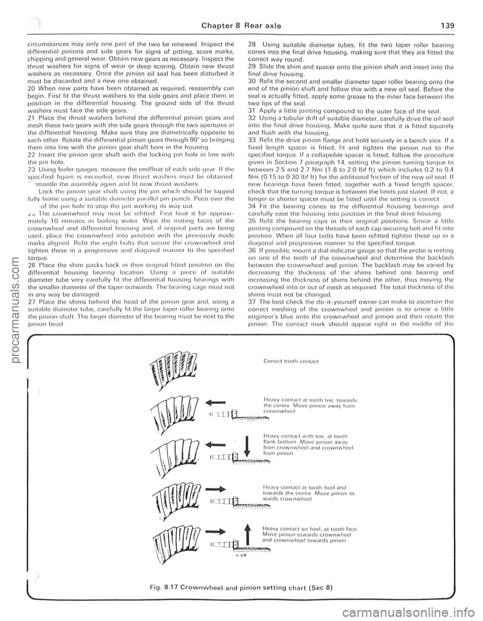
g iven in Section 7 paragraph 14. setting the pinion turning to'que to hetween 25 nnd 2.7 Nnt (1.810 2 0 Ihf It) which includes 0.2 to 0.<1 Nm (0.15 10 0.30 Ibl It) lor the ndriitional friction of the new oil senl II new hea,inns h~ve heen filted. logether With n li~e(l len(Jth SP,lCer. check thm the tOrlllllg torque is bel ween the limits just stmed. If not. a longer or shorter spilcer must he I,tted until the setting IS correct 34 Fit the healing cones to the cf,fierenllal houslIlg heallll(Js and carefully ease the housing Into posilion in the finill drive housmg 35 Relit the be,IIII'!J CilpS in thell originnl pOSitions. Srnc,ll n httle JOlntmg compound on the threilcfs 01 each cnp secuIII'O bolt nnd fit 11110 position. When ,111 low halts have bcen rein ted tiUhten these up in a (h"IJonal and progresSive milnne, to the speCi fied torque. 36 I I pOSSIble. 1Il00nt n dlnl in(licntor onu(Je so thnt the probe IS resting on one of the teeth of the crownwheel and determine the backlash hetween the clownwheel and pillion. The bileklash may be vMicd by elecreasll'\) the thickness of the shims bellind one beilling nnd incrensing the thickness of shirns behind the othcr. thus moving the crownwheel ;nlO or out ofmcsh as requi,ed. The tOt.llthlckness 01 the shims must not be chnn\)ed. 37 The hesl check the do·it·yourself owner cnn make to aSCerta", the correct meshinu of the crownwheel ilnd pinion is to smear ,I htt le engineer's blue onto the crownwheel and pinion iJnd then lot"te the pinion. The con1
_
t Heavy conWCl 0" huel. at 100lh !,leu Move p'",on lowa,ds crownwhcd u:.!:.crt:1 3nd c,ownwhuel towards p,n,on
.~\;!~" •. ,;.';,;,"",.,=,"--
l ' Fig. 8.17 CrownwheeJ and pinion setting chart (Sec 8)
, ,
, ,
"
procarmanuals.com
Page 145 of 205

144 Chapter 9 Braking systom
9 II there Dre no inspec tion holes, remove the wheels and drums In inspect the linings . 10 Where any lining is less Ih,111 the nllnimufll thickness, renew Ihp. complete SCI 01 re,ll b,~ke shoes. 11 Refi ' the drums lind wheels as necessary then lowe. tho em \0 thl) 9lOund.
Ch eck operation of servo lIoil 12 Visually inspCCllhe vaCUUll1 hose IClIding hom the inlet mlllllfolll Of air box 10 the servo unit fOf dc\c,iOf1l1lon and security. 13 Wit h the engine Slopped. dCI).es s the bra ke pedal several ,imes to dissipate t he VOC U\Ull hoUl the sorvo Imit. 14 Depress the b'i1kc 11Cdll1 wilh moderate pressure then Sin' I the
cnU illC . As the V
R/mew fhe /)rilke I/Ilid 21 lJIucd Ihe hyd.; ."loc sySle m as d"scllherl III Seelloll 15 ilUOwnl! II",
Ihe new h ,,,k\) Ih"d to COnlph: lely 1,lIlhe C:"CUtt he"I!1 bled . 22 AI Ihe sanl\) I"ne rcn,uve Ihe 'Ci" ",ake \I'lOn,s alld check tho wlu,,,1
cylonclers 10' leak"IJe.
3 Front disc pl1ds - renewal
Apply t
he handbr
I .
. ~ .. " ,) •. :Y.
2 RemOV(l Ihe hont wheels.
3 It Ihe fhnd level in the maste' cylondel reservoir is high. when the pistons l1re moved into thei, respecI,ve bo,es to accommodate new pi1ds. thO leyel could rise sulticienlly fo, Iho fluid 10 oyerflow. Place ilhsoruent clOlh .1round the reSe,yO". o. syphon a Imlo Ituid oul. so 1)'Cven tUlg Pil"ltwOlk
<1 F rollt brake caliper _ rcmoy'll iltld refitting
1 nemove the f,on! disc pads i1S tie sc"lJc(/ in Section 3. 2 1111 'S Itll,,,,d,,(1 10 lit ncw Ci1tiper pistoll s "nd/o, seals. dep,ess the tH.1k'J Iwel,,1 10 hlUlU the pistons i"to COI11i1ct with thO (fisc and
'-.. ~
, .
3 .9B Fitting the tenS ion springs
.--.::.:.:; .
....... . ~,'
灲潣慲浡湵慬献捯m
Page 152 of 205
-
)
Chapter 9 Braking system
,,-
")_'J ,
: ~~ 11111JIII/IIIJ II /I /III Ii hIIllllIlIlIllllIlll 11111#111111 III! -------
8
9
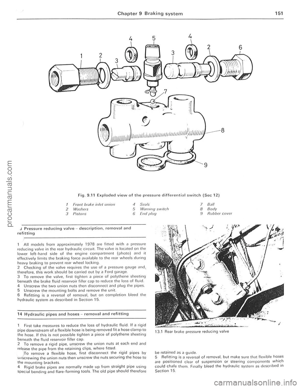
Fig. 9.11 Exploded view o f Iho pressure d ifferenti
J Pressure reducing vulve -description. remalln' nnd refitting
<1 SCi/Is 5 W,If/ll//y $wl(ch (j [lid ilIIIY
All models from ~pproxirniltely 1978 me lilted with il pressure ,educing valve in the rC~f hydraulic Cifelli!. The IInlve is IOCillCd on the lower Icft- hJrHJ side of the engine compn((mcnt (phOIO) ,mel 11 effectively limIts the hrakin\1 force DV
5 Unscrew the mounting bolts ,md remove the unit.
6 Refitting is a reversal of removal, but on completion bleed the
hydraulic system as descrihed in Section 15.
1 4
Hydraulic pipes and hoses -removal and refittin g
7 8.1/1 8 Body 9 R(lb/w( cover
First wke meilsures to reduce the loss 01 hydraulic fluid. If ~ rig id
pipe downstream of a fle~ible hose is being removed fit ~ hose clamp to
the hose . If this is not possible tighten a piece 01 polythene sheetinu
beneath th e livid reservoi r filler cap. 13
.1
Rear brake pressure reducing valve
2 To femove a figid pipe, unscrew the union nutS;]1 each cnd and release the pipe from the retaining ctrps. wh(Jre /riled.
be retained as a gUide.
151
)TO remove 11 fle~ible hose, lirst disconnec t the rigid pipes IN u"screwing the union nuts then unscrew the nuts securing the hose to
the 1l10unting brackets .
4 RiUid brake pipes arc normally made up from straight pipe using special bending <.rnd flare· forming lools. The old pipe should therefore 5
Refitt ing
is J revNsal o f removal, but make sure thJtlle~ible hoses
arc positioned clear of suspension or steering cOlilpo rwnts which
could chafe them. Finally bleed the hydrauhc system as deSCribed in Section 15.
••
procarmanuals.com
Page 157 of 205
,
156 Chapter 9 Brakin g syste m
Secondary cc1ble (early models) 5 Loosen 1I1c lock.nut ~nd unscrew the adju stment ferrule from the right-hand rear clevis.
6 Remove the split pin and clevis pin securing the secanda.v caulo \0 the left-hand Icar operating le ve l. 7 htrac the clip, remove the clovis pin. and withdraw the pullcy wheel from the lever on the Ical a~le. 8 Remove Ihe cable from the lever.
Transverse rod (later models) 9 Disconne ct the cable from the righi-hand rear opCfating Icvcr by
removing the split pin and clovis pin. to Uncl.p the cable hom the 'Hlnsvcrse rod . 11 Remove Iho spli, pin and clevis pin securing the fod 10 the Icft·h~nd le;!1 operating lever . 12 Slide the transverse rod Irom the guide on the rOM axle . 13 Check thO {luide bush lor wear and dama ge and renew It il necessary by prising il oul and pressing a new bush irllo POSilioll.
All models 14 Refining is a r e versa' of removal. but lubr icllto the lin kage as )scflhed in Section 2, and atljl' stthe cable as (fescri bed in Section 18.
21 VilCUUrll sorvo unit -dosCrilHion
A vacuum servo unit is linod Into the lir,lk e hydrallirc cil cu il. 111 series with I he 111,1S ler cylinde f. to provide assiswnco to the dllver whlln Ihe brake pedal is depressed . Thi s reduces the eHolI le{luired try the driller to oper,lIe the brakes, under all brak ing condi tions .
This unit operates by vacuum, obtained from Ihe indu ction mnni rold and comprises basicall y iI booster diilphragnl and check lIallle . The servo unit and hydraulic master cylinder are connected
t o gether so that th e serllO unit piston rod acts as the master cylrnder pUShrod. The driller's b rilking ellon is trilnsmitted through allot her PIi ShlOd 10 the serllO unit piston and ils built-in COmrol system . The scrllo unll pislon docs not fit tightly inro the cylinder. but has a strong ,lltl flhril!Jlllto ke el) liS edges in COllst ilnt COntaCI with I he cylinder Willi_
23 rilult diagnosis -hrilking system
~ylllptom
-'ceSSllle ped,,1 u;tllel
nrakcs pull 10 ono Side
Or;tke ludder
E~cessive eHor l to stop car
so ensuring an i1inigh t seal between the two parts, The fo rward
chamber is held undelllaCUUm condi tions cleilted in the inle t manifold of the engine and during periods when the brake pedill is not in use, the controls open a passtlge 10 the rear ch ambe ., so placing it under lIacuum conditions as well. When the b.ake pedal is dep.essed. the lIacuum pass.Jge to the rear chamber is CUI oH and the chamber expos ed to atmospheric pressure. The consequent rush 01 ail pushes
the servo piston lorward in tile lIacuum chamber and operates the main push rod to the m.Jster cylindcl. The controls are designed so that assistance is given under all condllions. When the brakes are 1'101 requ ired, vacuum in the rear chamuer i s .e -es tabl ished when the br.Jke ped.J1 is released . All air Irom the atmosphe.e entering tho rear ch.Jmbe. is passed through II sma ll air trlter. Und er normal opcr.Jting cond itions tho IIflC(IUm serllO unit is lIery relraule and does not require ollerhaul e~cepl at IIcry high mile,1geS. In this case it is far bcner 1 0 o bta in a serllice e~hange uni l. r,1the, than rcp;ti . the o,igi'lo11 unit . Although inlernal components we,e once .Jv'lIlaule 10 ' ovcrhauling purposes this service has no w been
d,scont,nue(t .
22 Vacuulll servo unit _ remOlla l MId re filtillg
I RemOIlO the master cylinder as desc.ihed In Section 10. 2 D,scolllwc l thc vacuum hose from the non·return lIalve on the serllo \lI1it. 3 Work i,,!) insido thc cal. remOlle th e lower l;t cia panel below the stccring column. 4 E~tractlhc clip and l)ul1 outlho clellis pin attaching Ihe push.od to the l ootu .ake ped;t!. 5 Unsc.ew the nuts securing thc mount ing b.ack.et to the bulkhead.
then withdraw thc serllo unit and bracket from the engine COlllp,lJtlnen t, 6 UnSClew th e nuts ar1(1 serlar,lle the braket 110m the SCIIIO uni, . 7 netrning IS;t rell e.sal 0 1 remOllal w ith leference .Jlso 10 Section 1 0 when retrumg Ihe master cylrnder.
Renson(s)
RC.Jr blake self adju sting mechanism faulty All i n hydrilulic system
WOIll or cont,llllina led /rnin{Js Seized Caliper or wheel cy linde r
E~cessille run-out or distortion of discs o. drums
Worn Of cont aminated linings Brake backplate or caliper l oose WOIll suspensio n bailloints
SerllO unit faulty
Worn or conwmin.Jted linings
I
J
procarmanuals.com
Page 162 of 205

Chapter 10 Suspension and steering 161
fig. 10.11 Drivebelt [ldjustlllent pulley holts on 3.0 litre models -arrowed (Sec 2)
2 Routine maintenance
At the "*',vals spec ,f,ed III the Routine MainhHlance $()(;t,on in the front of til() manunl c,lIIy out the 101l0wlIl\j p,o(;cdures.
Check lyres for illflalioll, wear and conditioll 1 Check [lnd If necessary adjust the tyre pressures .
2 Check [III t yres for WC[lr and condition with referenc e to Section 21
Check power steering pump drive belt tensiof) 3 Check thm the deflection of the drivebelt m,dway ulon!) its lonyest nlll between upper pulleys is approxirn
(photo).
Clwck puwer steering fluid levef (lnd hydraulic huses II pOSStble the level should be checked w,th the Buid [It nOll1lal
uper,\!mg tClIll)Cr[lture . 6 On c;lrly modcls unscrcw the wing nut nnd relnove Ihe rese,voir cover ilild uaskel. The flu,d should be up 10 Ihe MAX level mark on the
reservo". 7 On later models, wrn tht! hiler C
Fig. 10. 5 Topping·up the power steering reservoir on early models (Sec 2)
8 Whele nec.ess.1'y ~dd Ihe ~pccilled lIU1d to bring Ihe level up to the
correct ,nilrk. 9 ChC(;k the hydr[luhc hoses for comJit,on and security.
Check steerinfj ,-md suspension components 10 n,ll$O tilt) front ilno reM 01 the Cill or position over an inspeclion pn. 11 Check the SleetinlJ wck and t'e 'rods for d[lm3ge und weM. Also check the wek HJbber bellows and track rod end rubber bOOIS for spfilS
ilnd leilk[lge. 12 Chec k the front ,md reilr suspension components lor d"m.Jge [lnd wear. In particuf;lr check the front suspension tr.Jck control Mm ilrod stahiliwr r"bber mounling bushes. Usc a lever to check that there is no excessive we[lr III the Iron I slispenSlon lower IJ[ll lJoints which Me
"'\()\JIill wnh the track conlrol ilflllS . 13 Check the operat,on of the I,ont ;IIHt rear shock absorbers This is
be st ilchievcd with thO} Cilr on the \lfOlind by depressing euch corner of the ca' 1111\I1. On 'ele[lsil\ljthe C()"H~r helllU checked Ihe body should ,,~c thell s"llie IIlIl11ed,mely on ,t~ way down. II there nrc sever.J1 ()sclll;ot'ons the sho(;k absorber IS weilk nnd should be renewed.
3 Front hub _ removal. refitliny and bearing adjustillent
Apply the h[llldhr[lke then Jilek tip the front 01 the cm ilnd support
on axlt! standS Remove til(! rOildwhecl 2 Rernove the front ul;lke CJllper With ,elerence 10 Ch.Jpter 9. Whele the flex,ble br[lke host! is connecte(t dueclly to the cililper ther e IS no need 10 disconnect the hose i1S thO} caliper can be suspcnded by wire
aWily from the diSC. 3 By calelul 1
" :<>,:,~,.
Adjusting the power Sleering pump drivebelt tension on the 2.8 litre engine
2.7 Powcr steeling filler c.Jp/d,pstlck for the 2.8 hIre engine
3.3 Removing the dUSI cap from the front
hob
i
i ,
~ !
procarmanuals.com
Page 177 of 205
)76 Chapter 11 Bodywork and fitting
General description
The body is of all-s teel welded construction with impact ilbsorbing hont Dnd rear sections . Anli-burSllocks nrc lilted 10 the doors, ilnd the
t ailgDte is supponcd by \J
AI the in1erVills speCIfIed in the Routine M"IIl\cnilnCe section in the front 0 1 the nl
Check underbody protective coatiog 5 W,th the CM supponed on i1xle stilnds. check the cond,tlon 01 the un(lelbody protcctivc coating. i1nd wherc neceSSilry clean
M,,;ntcll
Wily to remove any aCCUIllUI,lted mud whIch WIll retillll mOlslu re
Mats and C
very line culling pils te. Finally, opply wax polish. WhNe the scrotch has penctrDt(ld right through to the metill of the bodywork. causing the mowl \0 rust. iI d ifferent repa ir lechnique is
required. Remove any loosc rus t fronl the bottom 01 the scra tch with a penknile. then apply rUSI inhibiting paint 10 prevent the lormation 01 rust in Ihe future. Using n rubber or nylon appliCiltor fill the scratch with bodystopper paste. II requ ired. this paste Ciln be mixed with cellulose thinners to provide a very thin paste which is ideal for filling narrow scratches. Before t he stopper·paSI(l in the scratch hardens. wrilp il piece 01 smooth COllon rJg i1round the lOp 01 J linger. Dip the finger in cellulose thinners and then quickly sweep it i1CIOSS the surlace of the 5topper-pJste in the scratCh: this will ensure tha t the surfilce 01 the stopper,pilste is slightly hollowed. The scratch can now be p
first wsk is to pull the dent out, untrl t he affected bodywork almost
procarmanuals.com