1974 FORD CAPRI torque
[x] Cancel search: torquePage 88 of 205

Chapter 4 Ignition system
Contents
"'ondcnsc! (30 Iotre cnUIIlC) teslI llU . removal and rc h1!ln g .... 5 '"tact b.ellkc . POIllIS (3 .0 litre CIlUIIlC) ,lI 11us1mC lll 3 ConlilC ! brCi.ke< POintS (30 lIue cnumc) -Hlllloval fllIIl rclr ninH . " f" '~lnb\llo, (1111 CIl\ Ji llCS) lema",,1 .lIlt! .cll1l1n\) (j nhlllOr (28 lilre Cilomo) -overhalll.. 8 D,stributor (30 h\le cnuinc) overhaul . 7 Faull diagnos is -iUm\loll system. 12
S rICcificin ion s
System ty pe
3.0 lit.e engine 2.8 litre engine
Convent ional ignition
Distributor
ROIDlion Condense, cnp
c 1 !H6 model yC
I',im
Type Elect. ode U
8reaker/ess igllilion
Distributor
Rotation .. HT lead rCSlstn llCe .
Firing order
Ignition timing
Coil
Primary rcs,sWnce
Secondary resis lan ce ............... .
Spark plugs
Type Electrode {jap .
,1/ systems
Torque w rench settings SpD,k p lugs (3.0 litl(l CIl!JUlC) SPD,k plug s (2 8 hl,e engine)
Geller,11 dCSCfll>, ioll 19r1lllon tnnphlicr Inodule (2 8 hire engine) -. emov,l l and 'Ch1tmO ... ......... .............. . IUrlltlon timinlJ -ndJuslmcnl . flOulUl!) Ill;untenancc . Spark plugs -rem Oval, servicing an d .cl'!lu \g ,
ConvcmiOllill. with cantilCl tu cilke. Br eake rlcss. clCCltOnic
Clockwbe 0 2110025 mid
0 .61 mm (002510) 36" t o <10 · 30000 ohm mOlX"U,uU 1 <1 2 5 3 6
10"' B1 DC 11\· BTDC
0!l5 10 1.60 ohm 50001 0 !l300 o h m
M ot
o,,,,,lt AGR 22 o. Ch;lIllp lon RN 9Y C 060 IlHIl (0024 in)
Cl ockw,se 30000 ohm Il1
BTOC
0 .
75100.85 o hm 5000 to 6000 ohm
Moto"ra" Super AGR O .GO mill (0024 in)
N rn 30 to GO 25 to 38
22C 0' ChJlllplon RN 7YC
Ibl It 22 to 30 1 8 to 28
10
9
2 11
procarmanuals.com
Page 97 of 205
,6 Chapter 4 Ignition system
9 The spark plug gaf} is 01 conside rable impor1~e. as. if it is too lilrge or too small. the size of the spark ilnd its efficiency will be seriously impilired. The spilrk plug should be set to the ligure given in thl} Specifications ill the beginning of this Chapter; IOTa sel it, measure the gilp with a/cere, gauge. and then bend open. or close. the outer plug electrode untillhe correct gap is achieved. The centre electrode should never be benl as this may crack the insulation ilnd cause plug fAilure if nothing worse. 11 Relit the plugs, and re/ilthe leads from the distr ibu tor in the correct I"ing order. which is given in the Specifications. Screw the plugs in by hilnd initiilily then tighten them to the specified torque using the plug spilnnel.
12 Fault diagnosis -ignition system
By lar (he nlo1jori (y 01 brCJkdown and running troubles ilre caused by InUits In the igrlOlron system er(her in (he low (enSlon or high tens ion circuns There
Engine fails 10 staft 1 If the engine falls to StM( and t he cal was IIJnning norll1t1l1y when.t wns IJst used, first check ther e is fuel in the petrol wnk. If (he engille tums ovel normally on (he starter 1I10tor and the bilHery is evidently well chmged. then the lault mny be in either the high or low tension circuits. Firs( check Ihe HT circuit. Note: If lire hal/cry is known 10 hI! {(Illy ch,}lged, Ihe ignilion liglll cOllies on, ,1I)d Ihe s/arler 1II010r {,lils /() tum IIIe ongine check the tightness o f the le'lds on the biltlely terillinilis ,1I)d <1Iso (lte seCUIIHWSS oflhe e,l,th leold (0 irs cOllllec/ion 10 tire body It is qui(e common for tlie le,1(ls /0 Ii,}ve wOlked loose. l.'vc'1I If Ihey look ,1n(/ lecl seclI,e. /I one 01 the boll/my ((:{minM {Josts [11.'1.1' vC'IV liot wi".." (Iyiny (0 wOlk Ihe s/mler 1II0tOl (his is ;/ sUie IIId'C,7/IUI/ 0/ ;/ I;wlty COllllel;('On 1(1 1h.11Ie"lIillal. 2 One of tile commonest rOilsons lor bad stmtln!J IS wet or d;UllP sp,uk plug lead~ and dlstribu(or. Hemove (he distllblltor cap. H "JOdenSil(Ion is v iSIble IIlte!llillly dry the CJp With il rag and also wIpe ;lCf the leads nelu the cap_ 3 If (he enUiue sull fmls 1 0 St.l.t. check that cunent IS reachlllg (he JUS, by dlscounectln!1 ench plug le,l<1 in turn ilt the sp1Hk plllU end, .. ,ld holdlllg Ihe end olthe callie about 5 mm (0.2 Ill) aWilY from the cylillder block. Spin the enu'ne all the sta rter motor. 1 Spa,klllg between the end of the cable ilnd Ihe block should he fa"ly strong With J strong leuulm blue spark_ (Hold (he lead WI(h wbber to ilvold elec(IIc shocks) If Clluelll is reilching (he plugs. then rel110Ve them and clean and reg,lp them. Tho engine should now SWrt 5 If there is no spilrk ilt the plug leilds. wke of! the HT lead from the cenlre of the d'sltibutor C
Engine misfires 10 If the enOlnr. mlsfues re!Julariy. run It ilt a f~st irllrng speed. Pull off eilch 01 the plu(! C,lpS III hUll nnd hsten t o (he note 01 the engrne. Hold the phl(J cnp In il dry cloth or with a rubber g love
(,J) The cOllm.lV be {,lufly giving ,111 iniNmil/elll mislile (b) Thele limy he ,1 (/iJmiJged wile or loose cOrlflee/ioll in till! low (eflsion circuil (c) The condensel /II,lY I;e shOll circuiling (i{ filled) (d) There nwy be a meehanic,lllolUI! IiI Ihe dis/flbll/or (bfOken dliving spindle or eOlllac/bleaker spring. if filled)
17 If the ignition (iming is too far reto1lded, it should be noted thallhe engine will tend to overheat. and there will he a quite no(iceable drop in powel. If the engine is overheating and Ihe power is down, and Ihe ,oni(ion tim in!) is correct. then Ihe carburenor or fuel injection should be checked, i1S ,I is likely that this is where the Iilult lies.
procarmanuals.com
Page 98 of 205
Chapter 5
Contents
CIUICh il$scmhty '"SIJoCcl'Qn . Clu\(;11 assembly 'Urn!!ll!) Clutch llsscmhly lemOY," C lutc h cilhle .efluwal._
Clutch
Clutch !Jedal rClllovnl illld ,cflltl"U
Specifictions
Genera l Type ..... Clutch (lise (hamClcr lining tlnckncss Clutch pedal hcc "
Gene.al description
,
5 3 1 8
All manu:!1 transmission madllis covered by this manual nrc lilted Wilh a singlo dl3phrilgll SpllJlg clutch. The unit COlllt)riscs il steel cover which is dowelled and bolted to the tear lace of the lIywheci ilnd conla i.lS the pressure plnte. diaphragm spring and fulCrum .ings . The clutc h " iClio n disc is
ee to slice along the splineJ gearllox
Inpu t Shillt and is held in posi t,on between the flywheel and the pressure plate by the pressure of the pressure plate spring , Friction linIng materiill is riveled 10 the d,sc and II has a spring cushioned hull to absorb transmission shocks and to help ensure a smoo th take oft. The circular diaphrilUm spring is mounted on shoulder pins ilnd
'Ield in place in the cover b.,. two fulcrum rings . The spring is also held ,0 th e pressure platc by three spling steel clips which are rive ted in
posi tion .
The
clu tC h ,s aCluated b.,. a cable controlled b.,. the clulCh pedal.
Clutch '0Ie,150 bCilfl"U -remova' and wl,u,"g Filult (ioilU"OS'S -clutch Generill descllptlon . noutlilc rn,untenanco .
SlIlgle (Iry plate. dlill)hragm sprong. cilhle ·ope.ated 241,3 rnm (95 Ill) 381 nun (0 15 In) 27.01 40mm (1.OG:i 0 .16,n)
No. Ib l It 16 to 20 12 10 15
G 9 1 2
The clutch release mechanism consists 01 a .elease leve. and a bearing which conwcts the lelease Imgers on the pressure plilte assembl.,.. The eHect of an.,. wear of the friction ma terial in the clutch is adjuSled out b.,. means 01 a cable adjuster at the lowel end 01 the cable where it
passes through the bell housing .
Dep.ess lng the clutch pedal actuates the clutch release leve. b.,. means of the cable . The lelease level pushes the lelease bearing
forward to bear against thO release l ingels so moving the centre of the diaphf()gm sprong within the annular rings which act as fulcrum points.
A s th e centrO of thO spring is pushed in. the outside of the Spling is pushed OUI. so Illoving Ihe pressure plme backward and disengaging the p.essu.e plate flom the /tielion disc . When the Clutch pedJI is Icleased. the diaptllaglll spring torces the plessule plate into contac t w ith the frictIon linings on the d,sc and at the saIne t,me pushes it a flactlon 01 an InCh fOlward on I\S splines . The
disc is now fuml.,. sandwic h ed between the plcsswe plnte Dnd the
flywheel. so the d.ive IS laken up.
procarmanuals.com
Page 104 of 205
Chapter 6 Manual gearbo x and automatic tran smissio n
F1VO.Sp()od \joiuhox:
'" 2nd 3rd 41h .. 51h f\ovr;,so
Laysh aft cluster gear (f our-speed gearbox )
Elldfio
Luh"(.
InplIl shafT hoaun» 11,IJIIUlr ExtellSl!lIl hous',,» ... Sf:h,ClOr Shilh IJJil~kel . Sciccto! housinO cove, .... Extension housin\1 cover . GeJlhO x casc cover
Flve·spccdgc,lfbox Guide sloeve Ex lOnsion housing. Geol,hox top cover Seleclor locking mechanism .... FilII), plu(1 51h He,ll cull,H nul 5th
Type
Torque converter
if! IWtlO
Transmis s io n ra tios
1 st 2nd. 3'd . Reverse
Lubricant
C~pacily (ilpprOX) . Type :
Early models (blnck dipsl ic k ) Laler Illodels (red dipstic k) ..
T orque wrench settings Torque convcrter 10 dr;veplille .
Do wnshift cable brac ke l
Downshift lever nUl: Duler. Inner.
Inhibito r swilCh
R'ake b;"Uld ~d!usling screw loc knu l .. .
lid l ine .... ... .. ...... ........................... .... . ULI cooler Ime . AU10lllilllC t",n~lI1ission t o engine. To rque conveilei drJin plug
3.36 : 1 1.81.1 1.26: 1 1 ,
0.825. 3.365 :
0.15100.45 mill (0.006 to 0.018 in)
1 .55 to 1.60 m!11 (0.061100.063 in)
SAE 80 EP oil 10 Ford spociflCatlon SCM 2C 9008 A
20 lit,e (35 pim) 1.9 lilH! (3.3 PUlt)
NIl
39104 8 30 to 37 35 to 4 1 17 10 2 1 54 to 61 71010 161021 9 to 11 17 to 21
9 to 11 4 5 10 49 9 to 11
17 to 19
231027 12010150 21 to 26
2 1 1026
Ford C3
Tnlock (hydrnulic)
222.1
2.47 : 1.4 7 : 1: 1 2 11 : 1
7 .5
htre ( 1 3 2 pUl1)
Ih l It
29 10 35 22 to 27 261030 12 to 15 40 to 4 5 5107 12 10 15
7 to 8 1 2 10 15
7108 331036 7 to 8 13 10 1 4
17 1 0 20 89101 1 1 1610 19
16101 9
ATF to Ford spec,fIC~lion SaM 2C 9007 AA ATF to Ford specification SCM 2C 9010 A
N m Ill f It
361041 27 10 30
16 to 2 4 1
2 to 18
1
010 15 7
to 1 1 41 1054 3010 40
1 6 10 20 12 10 15
4 7
10 61 35 10 45
9 10 1 4 7 10 10
1610
20 12 10 1 5
3010 37 22 1
0 2 7
2 7
10 40 2
0 to 30
, . ,
!
.5 ________________ ........... ........
procarmanuals.com
Page 112 of 205
Chapter 6 Manual gearbox and automatic transmiss ion 111
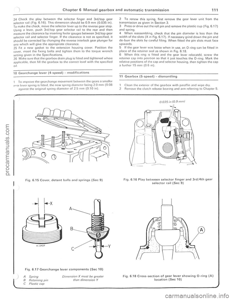
24 Chec k the plilY between the selector finger and 3.d/top geM selC{;lOr .a,1 (F,O. 6 .1 6) . lh,s d,mens,on shou ld be 0.9 mm (0.035 in). lo m"ke t he chec k. move the selec to. leve. up to the .everse gea. SlOp. Us.ng a lever. push 3.d/top gear selector .all \0 the rear and then
measure th e clea .ance by rnsel1lng leeler gauges betwee n 3rd/top gear selector rild "nd seleClOr finger. If th e cleM,mce 's no t ns specified. it shou ld he conecled by chnnging lhe .everse interlock geM plunger for one whIch will give the ,'PI).opria te clearance. 25 F,t a new gasket 10 the e~lension housing cover. Posilion the
cove •. ,nSOI I the fi~ing bolts nnd lighten Ihem 10 Ihe torque wrench Solt1inlJ g,ven in the Specifications. 26 M,1kc su, e th atthe geMl>o~ dmin plug is I,tted and tigh tened where apphc, 1hlc. then I,ll the uenlbo~ 10 the COffect level with the specl l'ed
,,'
10 Gcnrchnnge lever (4,sjleccl ) - m odificnlions
1 To ,mp,ovelhe \]flnr ch nngc movemcntlJctwecn lh(: Hea.s. , smallm CO".,r levcl Sl)!"'g ,s 1'lIr,<:I. the new 51)/,nU d,amclr'!' bc inU 20 mill (008 aga,nst the orig,n;r l sp.,n!) IIiarllctm 01 2.5 nUll (0 .1 0 inl.
Fig. 6 .15 Cover. d ewnt balls and sprinus (Sec 9)
Fig. 6.1 7 Gearchange lever components (Se c 10)
A Spliny B Rct.1illiny pin C Pf;JSlic C ilP
Dlillcnsion X mUSI be gloater Ilran dimension Y
2 To renew Ihis sp.ing. lir sl remove the gear lever unit from the trnnsmission as given in Section 3. 3 Press or drive out the roll pin and remove the plastic cup (F ig . 6.17 ) ;rnd spring .
4 When reassembhng. check that the pin di('!meter is less thiln the width 01 th e slots (X ,n Fig. 6.17), II necessary grind down the pin and
d e·llUrr the slots by ca.e ful filing . When filled the pin slotS mus t face upwMds. 5 If the gear leve. was loose when in use. an O-ring can be filled in placo o f Ihe retainer sOill as shown in Fig. 6.1 8 .
6 When this flng ,s fmed an(I the gear leve. reIOCalr:!d. screw the retainer cap inlO pos,tlon so th ilt It jus t touches th e O·ring . Mark the relntlve pOSitions of tile cap
1 Clean the e~tello. 01 Ihe gearbox w.th paraffin .,nd w.pe d.y. 2 Remove the clutch release beallng and allli lele",ng 10 Chapter 5.
0035;11 10.9 mill}
Fig. 6.16 Plav between selec to r finuer and 3rd/4th geM selector rail (Sec 9)
.. : . :,'. :", .
fLJ
··· ..
A
Fig. 6 .18 Cross· section of gear lever showing 0 ·rin9 (A) location (Sec 10)
i
i
procarmanuals.com
Page 115 of 205
Chapter 6 Manual g ea rbox and automatic transmission
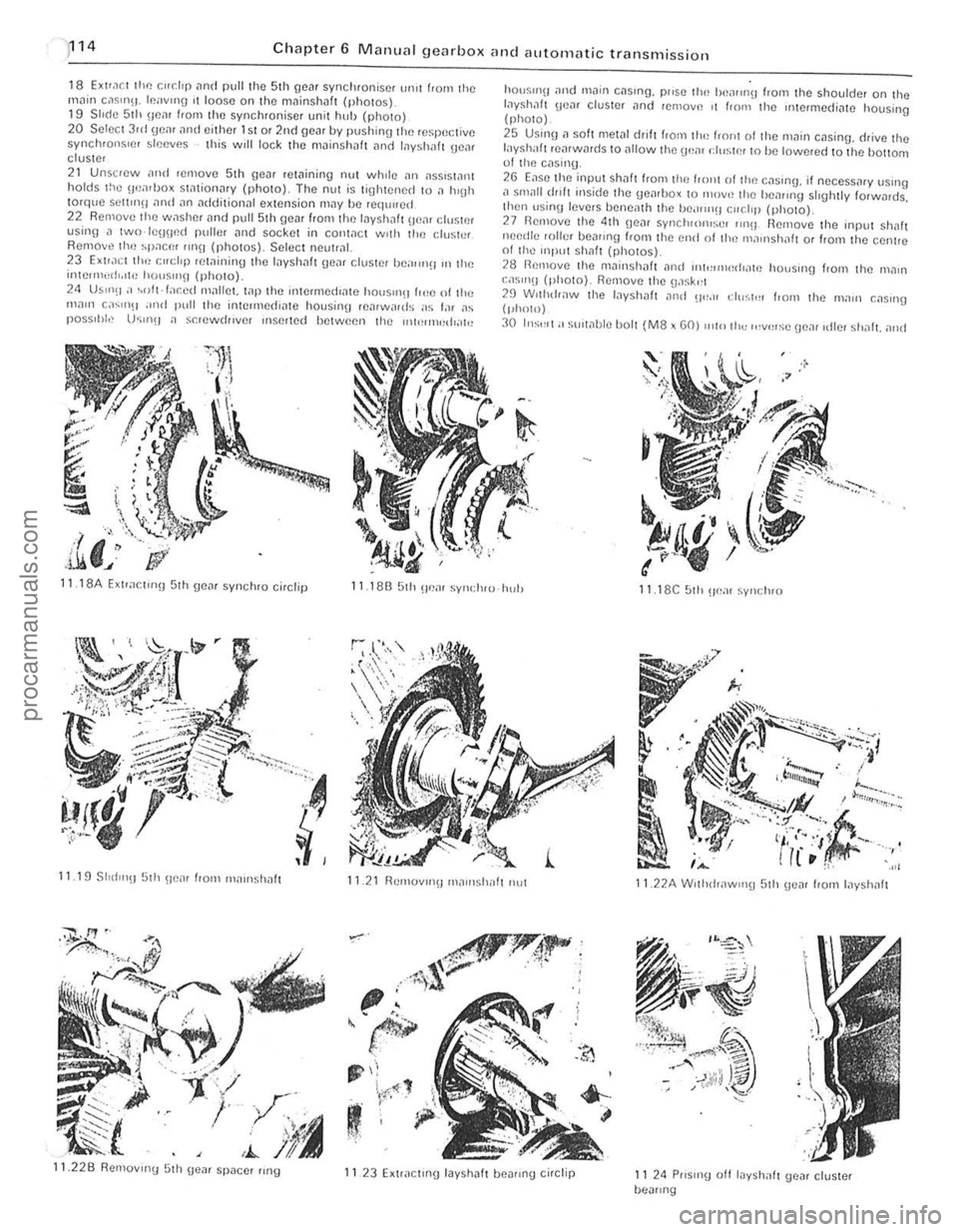
18 EXlra ct the r."dp and pull the 5th gcar synchronise r ur1lt f'orn the
rnn in c,lsm\1. Icavlllg I t loose on thtl mninshaft (photos). 19 S II(le 51h IlcM from the synchroniser unit huh {photo) 20 S elect 3rd gem and either 1st or 2nd gear by pushin\) the re~peclivc synchronsrcr sleeves this will lock the mainshllft
24 US"'(I;' ~oft·f;,r.ed Ill;-rllm. wp the intermedrate hOtJS"'~1 (,,!e of tl,,; ",<1111 c
.I,' ,i.li. J
hO(lSII1\1
layshilft rearwards to <11101'11 the \ .wm d,,~tn' t o he lowered 10 the hottoot 01 tlHl cas,,'U .
2G Ease tlte input Shaft f'om the frOllt 01 tlHl c;-rSlng, if oecess
29 Wllhdr,lW th e I,lyshalt ,11lel 0"_" eh";t,,, I,om Ihe 111<1111 C;-rSlIlg (phOlO)
30 In:;'''I; ' sUlwble bOl t (M8 x GO) Illto Ih" ,,,v',,:;c !Je,1( ,die, shnft. alld
11 18A Exlrar.t,nn 5th geM synchro ci,clip 11.18B 5th u em syl,(IHU hul) 11 18C 51h ~Je;-rr synclH O
11.19 SlId l"!J 5th !/tlar from "'
Page 120 of 205
) Chapter 6 Manual gearbox and automatic transmission 119
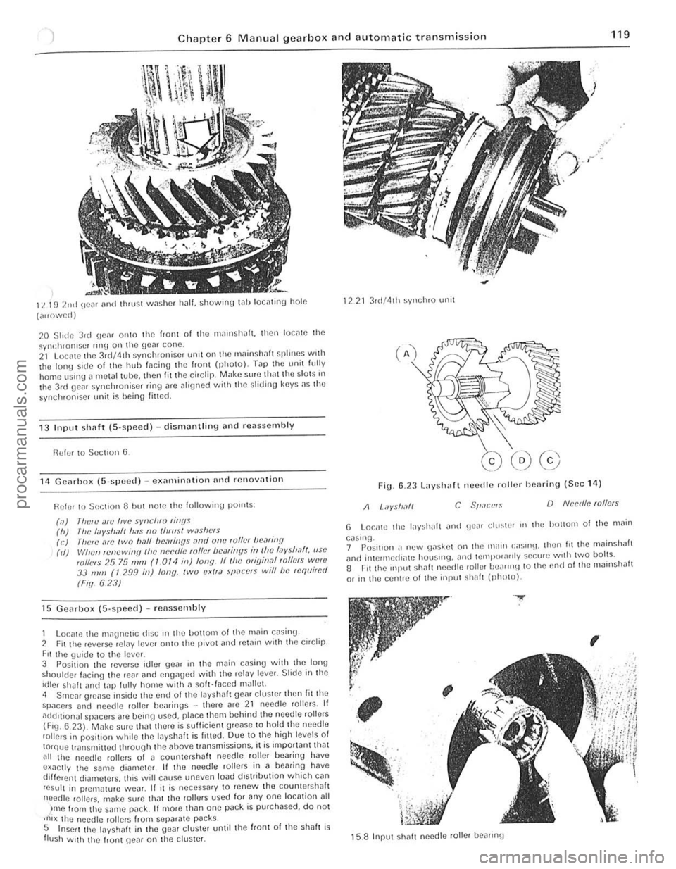
11. 1~) 2nd (Ie", [Inti thrust w,1shcf h.1l1. showioO t .. llloctltinu hole
(",,()w~d)
20 Slide 3ul \jC,lf 01110 the f,aiH 01 the mninsh
13 Input sh(lf( (S·speed) -dismantling Dnd reassembly
!'ld!;! to Section 6
11 GCil,ho)l ([i·spced) -C)lamin,lIion [In(1 rcnov[ltioll
Ref or 10501:[ '0 118 hut now the lollowlng pOllltS :
(,1)
111<:,,) ,1fI! five sYllcll,v rillYs (h) /IlL' I"yshlft lI[1s 110 IIIlIIsl w,lsllt"s (e) (lielL',1ro IWO ball-/)cmiIJYs ,lrId olle ,01lcI hCMiny (d) Wile" ,cnewi"y Ihc IIL'cr/lL' ,01lcI /)(1,1/ill[lS ill I!lc I,Jyslml/, (ISO wllels 25 75 111111 (1 OTt! ill) fony. IIlhc Oligin,ll ,ollers W{!lC 33 111/11 (T 299 ill) lony, two exll,l space's will be requi,ed
(Fiy 623)
15 Gcarbox (5'SI}Cc(l) -rC
Fit the \juidc to the leve r 3 Posit ion the reverse idler \Je~r in the m~in cDsill\j with the Ion,) shoulder facing the reill and en{lllued with thc ,eiDy Icver. Slide ill thc Idler shalt lInci t
)me from t he SMne l"JilCk It more than one pDck is purchased, do not ,ni x lho needlc rol lers from sepilrate p~cks. 5 Insert the layshJlI in the gear cluster unlil the front of Ihe shah is flush With the frunt \Ie~r on lhe cluster.
1221 3 r(I/41h syl1chro unit
Fig 6.23 Layshaft necdle roll.)/ he
G Loc,.tc the lilyshah iln!! gCilr ell/stP' III tho hOllom of the .11il;n
caslnu_ 7 Pos.1I0n ,. n(.'w \Jaskot on the Ill;nll (;;05"'11. Ihen hi the mllinshah ilnt! inlCrll1ed"l\C houslIlg. and IClllpor;I"ly secu.e w,th twO bolts. 8 Fit the mll"t Shilh needte roller heilrrn\J to the end 01 lhe mainshJlt
or In the centle 01 lho input Shilh (photo).
.....
,
~
; , .. '-; . '. ~, .
,
15.8 Input sh
i 1 ,1
I
procarmanuals.com
Page 121 of 205

)20 Chapter 6 M anual gearbox and automatic transmissio n
9 F it the 4th gCill syncluolliser "n9 to the 3rd/4lh sym;luOI"s(1f 'HUI with lhe c:ul-outs over the slidlllg k(lYs. then fit the UlPUl shalt asscnlhly i]n(l lilP the bearing fully into tho casing up 10 the rclo1llunu circtip (photo).
10 Invert Ihe \jCo1rilox so Ihil! the l
12 Us;n!).1 mel,lilllbe. lilfl the Inyshaf gear cluster be,IIPI'!J 11110 the inlcrmcd'
15 Seleci neulrnl. then slide 5th ge", IlItO mesh WIth the driVing Be",. 16 Slide the 51h gem synchroniser unll complete with sp"ce[ Onto 51h Oll"r. Then. usrng.l metal tube, drive Ihe dO\1 huh "lid 51h synchronlser flng OnlO Ihe 1ll",nsh,,11 splines whIle UlOld"l!) the synchronIse! 111111 onto Ihe shdlll[J keys. Fit the circhp (pholUs).
17
T"p Ihe sp eedometer drivegeilr "HO ItS COrreCI poslilon on Ihe mollllsh"ft -the dlsWllce belwoon Ihe HeM 'Illd the 5th gO,l[ dOll hub c"cllp should be 123.0 to 1 24 .0 111m (4 843 10 <1 882 Ill) (nhoto). lB Loc"le Ihc 5th He", selector fOlk In liS syn ch ronlSN sleeve "nd loc"le Ihe Interlock sleeve in Ihe uroov", hhol! Shollider 10 front). then InSurt the seleClor sh~1t through the sleeve ,1nd SeleCIOr fOlk InlO the "'aOll r.,lsll1\J (photo).
19 LocnlC the lSI/2nd "nd 3rd/4th Sf)I'~rIOr IOlks 1(1 Ihell respecllve ~Yllcillonlser sleeves. posilion the selectOl !ross
20 If If!rnoverl. 'ef'l Ihe seleCIOr sh,,11 (:"nlr,, 11~1I1!1 sprinU ",ui 51h \Ie",
.' /
15.9 FI1l1I1\1 Inpul shnl1 15.11 L;,ysh;r!t corruc tly located hefore inst,111,11101l 15.12 F,ltintllile Inysllilft hearing
15. 14A Tlghtelllng thc rn"insha fl nut
15.16B F'lllI'\) 5th genr synchlO to m~inshalt
15.148 Slak,n\1 the rH.lloslrall nul
15.16C 5th \le,,, haulk flng Jod hull
15.16A 5th gem synchro spacer
15. 160 51h gear hub {:ilchp
procarmanuals.com