1974 CHEVROLET CAMARO clock
[x] Cancel search: clockPage 17 of 85
Downloaded from www.Manualslib.com manuals search engine STEERING COLUMN CONTROLS
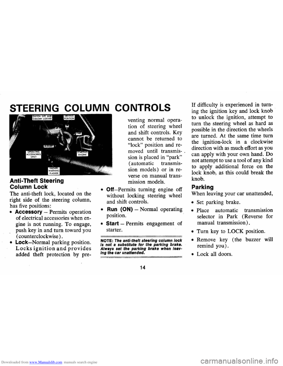
Anti-Theft Steering
Column Lock
The anti-theft lock, located on the
right side of the steering column,
has
five positions:
• Accessory -Permits operation
of electrical accessories when en
gine
is not running. To engage,
push key in and turn toward you
( counterclockwise) .
• Lock-Normal parking position.
Locks ignition and provides
added theft protection by pre- venting
normal opera
tion of steering wheel
and shift controls. Key
cannot be returned to
"lock" position and re
moved until transmis-.
sion
is placed in "park"
(automatic transmis
sion models) or in re
verse on manual trans-
mission models.
• Off-Permits turning engine off
without locking steering wheel
and shift controls.
• Run (ON) -Normal operating
position.
• Start -Permits engagement of
starter.
NOTE: The anti-theft steering column lock
is not a substitute for the parking brake.
Always set the parking brake when leav
ing the car unattended.
14
If difficulty is experienced in turn
ing the ignition key and lock knob
to unlock the ignition, attempt to
turn the steering wheel
as hard as
possible in the direction the wheels
are turned. At the same time turn
the ignition-lock in a clockwise
direction with
as much effort as you
can apply with your own hand. Do
not attempt to use a tool of any kind
to apply additional force on the
lock knob,
as this could break the
knob.
Parking
When leaving your car unattended,
• Set parking brake.
• Place automatic transmission
selector in Park (Reverse for
manual transmission).
• Turn key to LOCK position.
• Remove key ( the buzzer will
remind you).
• Lock all doors.
Page 26 of 85
Downloaded from www.Manualslib.com manuals search engine INSTRUMENTS AND CONTROLS
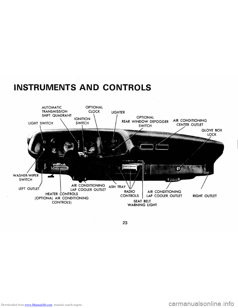
AUTOMATIC TRANSMISSION
SHIFT QUADRANT
HEATER ,-,.., ... ,T,,,,",'
OPTIONAL
CLOCK
(OPTIONAL
AIR CONDITIONING CONTROLS)
LIGHTER
OPTIONAL REAR WINDOW DEFOGGER AIR CONDITIONING SWITCH CENTER OUTLET
ASH TRAY
RADIO
CONTROLS
23
SEAT BELT WARNING LIGHT
GLOVE BOX
RIGHT
OUTLET
Page 29 of 85

Downloaded from www.Manualslib.com manuals search engine What to do:
1. Check that the parking brake is
released. If it is ...
2. Pull off the road and stop, care
fully-remembering that:
• Stopping distances may be
greater.
• Greater pedal effort may be re
quired.
• Pedal travel may be greater.
3.
Tryout brake operation by
starting and stopping on road
shoulder-then:
• If you judge such operation to
be safe, proceed cautiously at a
safe speed to nearest dealer for
repair.
• Or have car towed to dealer for
repair.
Continued operation of the car
in this condition
is dangerous .
. Headlight Beam Indicator
Light
The headlights of your car have
high and low beams to provide you with
proper night-time visibility
for most driving conditions. The
"low" beams are used during most
city driving. The
"high" beams are
especially useful when driving on
dark roads since they provide ex
cellent long range illumination.
The headlight beam indicator will
be on whenever the high beams or
"brights" are in use. The Headlight
Beam
Switch controls the headlight
beams (see Page 22) .
Light Switch
The three position light switch
controls the headlights, taillights,
parking lights, side marker lights,
instrument lights and dome lights
as shown. The headlamp circuit is
protected by a circuit breaker in the
light switch. An overload on the
breaker will cause the lamps
to
"flicker" on and off. If this condi
tion develops, have your headlamp
wiring checked immediately.
PARKING LAMPS
MARKER LAMPS
TURN KNOB TO
VARY INSTRUMENT LIGHTS
FULL Y COUNTER CLOCKWISE FOR DOME LIGHTS
26
HEADLIGHTS PARKING LAMI'S
MARKER LAMPS
Page 31 of 85
Downloaded from www.Manualslib.com manuals search engine Clock
Reset the clock, if your car is so
equipped, by pulling
out the knob
and turning
the hands clockwise if
slow, counterclockwise if fast. This
will,
if the clock error is five min
utes
or more, automatically com
pensate for time gain
or lag. Sev
eral resettings, several days apart,
may be needed to properly adjust
the clock mechanism. Have your
clock cleaned
and oiled by a com
petent clock serviceman at least
every two years.
Cigarette Lighter
The accessory cigarette lighter is
located on the instrument panel
face.
To operate, push it in. When
it becomes heated,
it automatically
pops
out ready for use.
Windshield Wiper
and Washer
The windshield wiping system
operates
at two speeds and is de
signed to wipe clear designated areas
of the
windshield under most
inclement weather conditions.
The
windshield wipers work electrically
and are not affected by engine op
eration.
Push the control lever to the
right to
start the electric windshield
wiper .
The two-speed electric wiper
has both a
"low" and a "high" speed
po sition.
Pressing the control will send a
measured amount of water
or other
cleaning agent onto the windshield
and will also cause the wiper lever
to move, thus starting the wiper .
motor. The wiper will then con
tinue to operate until manually
turned off at the wiper lever.-
Fill the washer
jar only % full
during the winter to allow for ex
pansion if the temperature should
fall low enough to freeze the so
lution.
• Check washer fluid level regu
larly-do it frequently when the
weather is bad.
28
• Use fluid such as GM
OPTIKLEEN to preventfreez
ingdamage, and to provide bet
ter cleaning.
• Do not use radiator anti-freeze in
windshield washer; it could
cause paint damage.
• In cold weather, warm the wind
shield with defrosters before us
ing
washer-to help prevent ic
ing that may seriously obscure
vision.
Ventilation System
Your Camaro incorporates a
ventilation system
that provides
ventilation comfort, made possible
by the addition of air vent provi
sions in the rear body lock pillar.
Another feature of the system
is
continuous low-speed operation of
the air conditioner blower, result
ing in an uninterrupted supply
of
outside air flow into the car when-
Page 42 of 85
Downloaded from www.Manualslib.com manuals search engine tive terminal (black color, "-" Engine Coolant
or "N") of the battery in the other
vehicle, and
THEN the other
end of the same cable to the nega
tive terminal of your battery in
this car. Take care that clamps
from one cable do not inadver
tently touch the clamps on the
other cable. Do not lean over the
battery when making this con
nection.
5. Start the engine in the vehicle
that
is providing the jump start
(if it
was not running). Let run
a
few minutes, then start the en-
gine in the car with the dis-
Jacking Instructions
charged battery.
6. Reverse the above sequence ex
actly when removing the jumper
cables. Reinstall vent caps and
dispose in a safe manner of any
cloths used to cover vent wells,
as
the cloths may have corrosive
acid on them.
39
Preparation
• Park on level surface and set
parking brake firmly.
• Set automatic transmission in
park. (Manual transmission in
reverse).
• Activate hazard warning flasher.
Instructions
1. After removing spare wheel
and tire, jack, jack
base,and
jack handle (wheel nut wrench),
proceed with changing the
wheel
as follows:
2. Remove hub cap
or wheel
cover with flat end of wheel
nut wrench and loosen, but do
not remove nuts, by turning
counterclockwise.
3. With column assembly seated
in base and lever in
"UP" posi
tion,
insert jack hook in
bumper slot.
Page 50 of 85
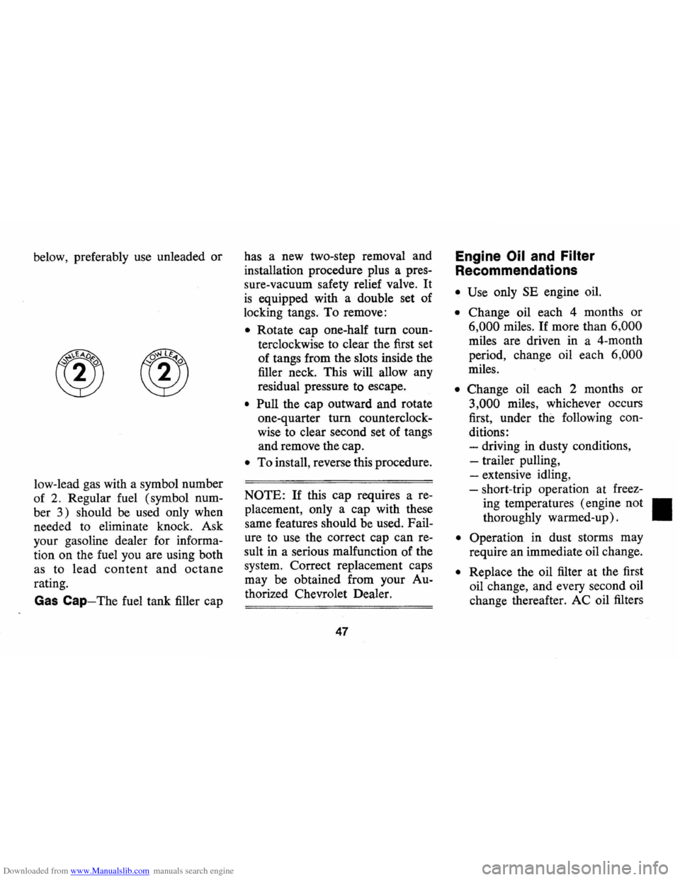
Downloaded from www.Manualslib.com manuals search engine below, preferably use unleaded or
low-lead gas with a symbol number
of
2. Regular fuel (symbol num
ber
3) should be used only when
needed to eliminate knock. Ask
your gasoline dealer for informa
tion on the fuel you are using both
as to
lead content and octane
rating.
Gas Cap-The fuel tank filler cap has
a new two-step removal and
installation procedure plus a pres
sure-vacuum safety relief valve. It
is equipped with a double set of
locking tangs. To remove:
• Rotate cap one-half turn coun
terclockwise to clear the first set
of tangs from the slots inside the
filler neck. This will allow any
residual pressure to escape.
• Pull the cap outward and rotate
one-quarter turn counterclock
wise to clear second set of tangs
and remove the cap.
• To install, reverse this procedure.
NOTE: If this cap requires a re
placement, only a cap with these
same features should be used. Fail
ure to use the correct cap can re
sult in a serious malfunction of the
system. Correct replacement caps
may be obtained from your Au
thorized Chevrolet Dealer.
47
Engine Oil and Filter
Recommendations
• Use only SE engine oil.
• Change oil each 4 months or
6,000 miles. If more than 6,000
miles are driven in a 4-month
period, change oil each
6,000
miles.
• Change oil each 2 months or
3,000 miles, whichever occurs
first, under the following con
ditions: - driving in dusty conditions,
-trailer pulling,
- extensive idling,
- short-trip operation at freez-
ing temperatures (engine not
II
thoroughly warmed-up).
• Operation in dust storms may
require an immediate oil change.
• Replace the oil filter at the first
oil change, and every second oil
change thereafter. AC oil filters
Page 58 of 85

Downloaded from www.Manualslib.com manuals search engine clockwise to detent (do not
press down while rotating).
• Wait until any residual pres
sure (indicated by a hissing
sound)
is relieved.
• After all hissing ceases, press
down on cap while continuing
to rotate counterclockwise.
CAUTION: To ,a~()/d' thedange, .• olbfling "l)~ned;tlo n(Jtl'entoveradiator «aP while
, engipe and radiator are ,stlll hot because $ca/ding ' flU./d·antlsteam' will be blown .
(1utunder pressure.
2. If necessary, run engine, with
radiator cap removed, until nor
mal operating temperature
is
reached and upper radiator hose
is hot (indicates thermostat
is
open).
3. Stop engine and open radiator
drain valve to drain coolant. (To
speed this operation, the drain
plugs in the block can also be
removed.) 4.
Close valve (install block drain
plugs, if removed) and add suf
ficient water to
fill system .
5. Run engine, drain and refill the
system, as described in steps
1,
2, 3, and 4, a sufficient number
of times until the drained liquid
is nearly colorless.
6. Allow system to drain com
pletely and then close radiator
drain valve tightly. (Install
block drain plugs, if removed.)
7. Remove recovery cap leaving
hoses in place. Remove coolant
recovery tank and empty of
fluid. Flush tank with clean
water , drain and reinstall.
8. Add sufficient ethylene glycol
coolant , meeting GM specifica
tion 1899-M, to provide the re
quired freezing and corrosion
protection-at least a 44 percent
solution
(-20°F). Fill radiator
to the base of the radiator filler
55
neck and add sufficient coolant
to the recovery tank to raise level
to the
"FULL HOT" mark. Re
install recovery tank cap.
9. Run engine , with radiator cap
removed, until normal operat
ing
temperature is reached.
(Radiator upper hose becomes
hot.)
10. With engine idling, add cool
ant until level reaches bottom
of filler neck and install radia
tor cap making certain arrows
line up with overflow tube.
It is the owner's responsibility
to keep the freeze protection at a
level commensurate with the tem
peratures which may occur in the
area of vehicle operation .
• Maintain cooling system freeze
protection at
-20 °F or below
to ensure protection against cor
rosion and loss of coolant from
boiling even though freezing
Page 76 of 85
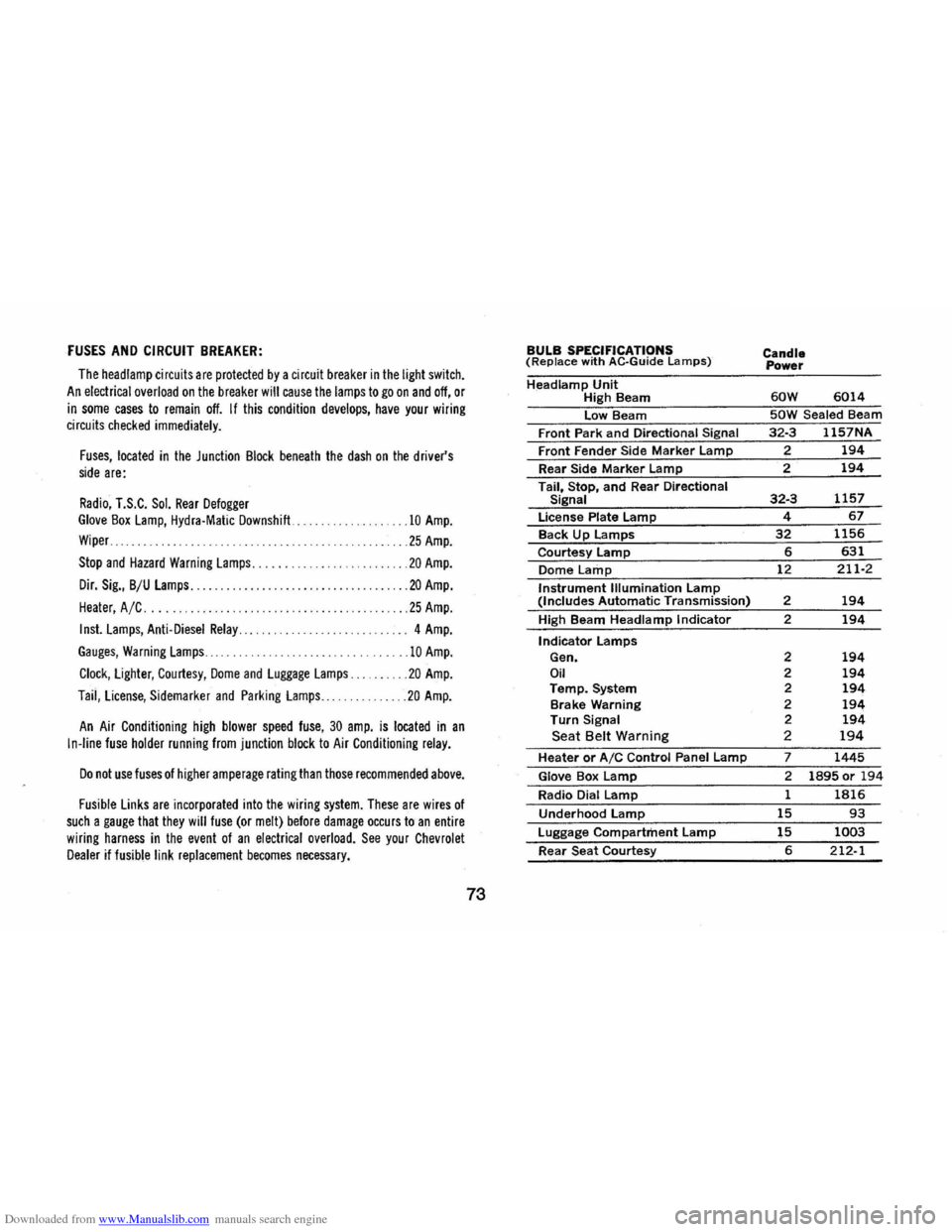
Downloaded from www.Manualslib.com manuals search engine FUSES AND CIRCUIT BREAKER:
The head lamp circuit s are protected by a circuit breaker in the light switch.
An electrical overload on the breaker will cause the lamps to go on and off, or
in some cases to remain off. If this condition develops, have your wiring circuits checked immediately.
Fuses, located in the Junction Block beneath the dash on the driver's side are:
Radio, T.S.C. Sol. Rear Defogger Glove Box Lamp, Hydra·Matic Downshift ...
Wiper ..
.10 Amp.
... 25 Amp.
Stop and Hazard Warning Lamps. . . . . . ... . ........ 20 Amp.
Dir. Sig., B/U Lamps........... ............. ... .. . ... 20 Amp.
Heater, A /C .... . .25 Amp.
Inst. Lamps, Anti-Diesel Relay............. ....... . .. 4 Amp.
Gauges, Warning Lamps ......................... 10 Amp.
Clock, Lighter, Courtesy, Dome and Luggage Lamps. . .20 Amp.
Taii, License, Sidemarker and Parking Lamps ... ..... 20 Amp.
An Air Conditioning high blower speed fuse, 30 amp. is located in an
In-line fuse holder running from junction block to Air Conditioning relay.
Do not use fuses of higher amperage rating than those recommended above.
Fusible Links are incorporated into the wiring system. These are wires of such a gauge that they will fuse (or melt) before damage occurs to an entire
wiring harness in the event of an electrical overload. See your Chevrolet Dealer if fusible link replacement becomes necessary.
73
BULB SPECIFICATIONS (Replace with AC·Guide Lamps)
Headlamp Unit High Beam
low Beam
Front Park
and Directional Signal
Front Fender Side Marker lamp
Rear Side Marker lamp
Tail, Stop, and Rear Directional Signal
license Plate lamp
Back Up lamps
Courtesy lamp
Dome Lamp
Instrument Illumination lamp (Includes Automatic Transmission)
High Beam
Headlamp Indicator
Indicator lamps Gen. Oil Temp. System
Brake Warning
Turn Signal Seat Belt Warning
Heater or AIC Control Panel lamp
Glove Box lamp
Radio Dial lamp
Underhood lamp
luggage Compartment lamp
Rear Seat Courtesy
Candle
Power
60W 6014
50W Sealed Beam
32·3 1157NA
? 194
2 194
32·3 1157
4 67
32 1156
6 631
12 211·2
2 194
2 194
2 194 2 194 2 194 2 194 2 194 2 194
7 1445
2 1895 or 194
1 1816
15 93
15 1003
6 212-1