1973 CHEVROLET CAMARO lock
[x] Cancel search: lockPage 6 of 84
Downloaded from www.Manualslib.com manuals search engine BEFORE DRIVING YOUR CAMAR 0
DRIVER CHECKLIST
Before Entering Car
1. See that windows, mirrors and
lights are clean.
2. Visually note inflation condition
of tires.
3. Check that area to rear is clear
if about to back up.
Before Driving Off
1. Lock all doors.
2. Position seat.
3 . Adjust inside and outside mirrors.
4. Fasten seat belts.
5. Check that warning bulbs light
when key
is turned to start
position.
6. Release parking brake (and
see
that brake warning light turns
off) .
7. Be sure you understand your car
and how to operate it safely.
Keys
Two separate keys are provided
for your car. Each key has a differ
ent cross section
so that it can be
inserted only in certain locks.
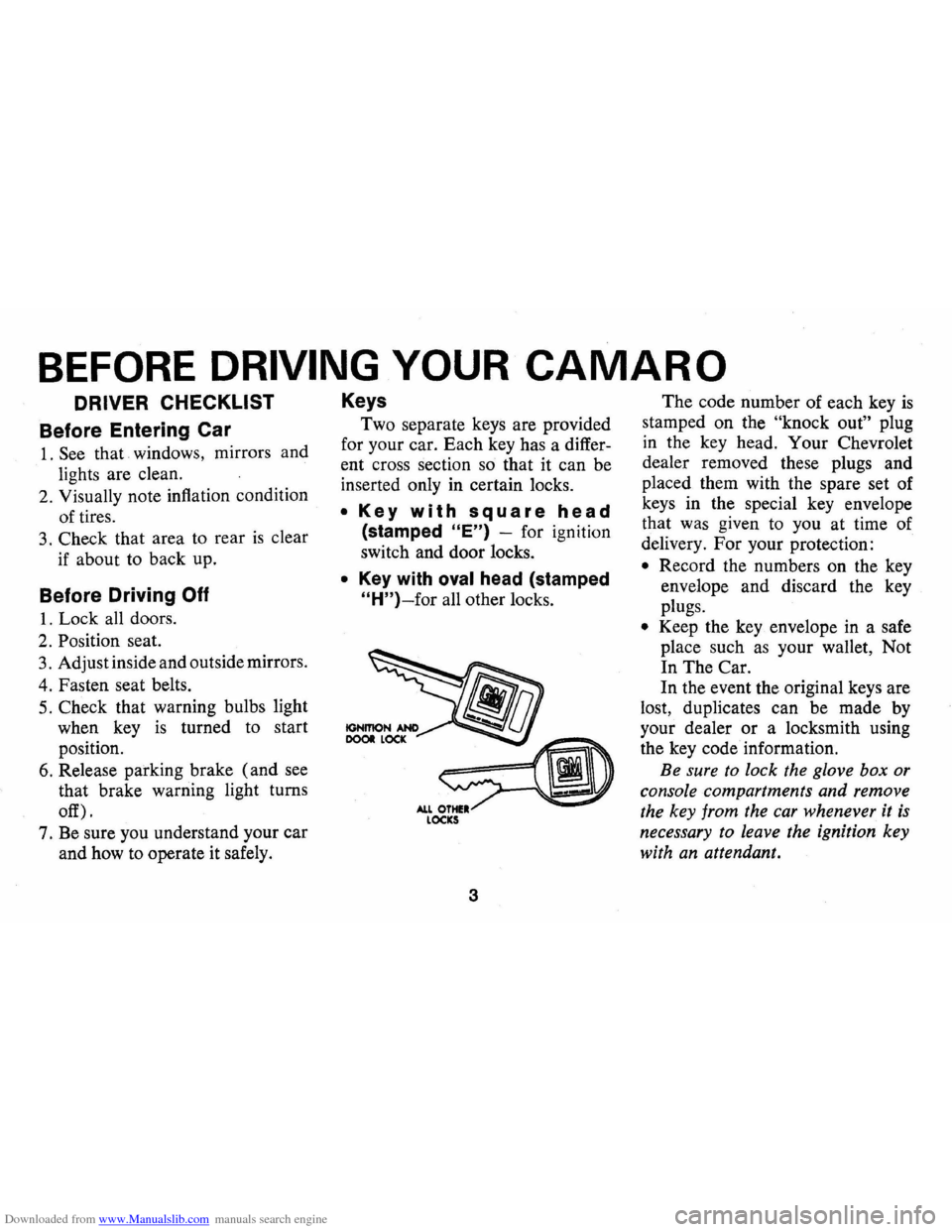
• Key with square head
(stamped "E") -for ignition
switch and door locks.
• Key with oval head (stamped
"H")-for all other locks.
3
The code number of each key is
stamped on the "knock out" plug
in the key head. Your Chevrolet
dealer removed these plugs and
placed them with the spare set of
keys in the special key envelope
that was given to you at time of
delivery. For your protection:
• Record the numbers on the key
envelope and discard the key
plugs.
• Keep the key envelope in a safe
place such
as your wallet, Not
In The Car.
In the event the original keys are
lost, duplicates can be made by
your dealer
or a locksmith using
the key code information.
Be sure
to lock the glove box or
console compartments and remove
the key from the car whenever it
is
necessary to leave the ignition key
with an attendant.
Page 7 of 84
Downloaded from www.Manualslib.com manuals search engine Door Locks
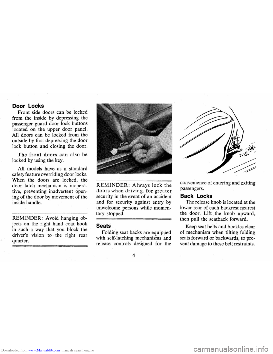
Front side doors can be locked
from the inside by depressing the
passenger guard door lock buttons
located
on the upper door panel.
All doors can be locked from the
outside by first depressing the door
lock button and closing the door.
The front doors can also be
locked by using the key.
All models have as a standard
safety feature overriding door locks.
When the doors are locked , the
door latch mechanism
is inopera
tive , preventing inadvertent open
ing of the door by movement of the
inside handle.
REMINDER: Avoid hanging ob
jects on the right hand coat hook
in such a way that you block the
driver 's
vis ion to the right rear
quarter.
REMINDER: Always lock the
doors when driving, for greater
security in the event of an accident
and for security against entry by
unwelcome persons while momen
tary stopped.
Seats
Folding seat backs are equipped
with self-latching mechanisms and
release controls designed for the
4 convenience
of entering and exiting
passengers .
Back Locks
The release knob is located at the
lower rear of each backrest nearest
the door. Lift the knob upward,
then pull the seatback forward.
Keep seat belts and buckles clear
of mechanism when tilting folding
seats forward
or backwards, to pre
vent damage to these belt restraints.
Page 8 of 84
Downloaded from www.Manualslib.com manuals search engine Manually Operated
Front Seats
The front seats may be adjusted
to suit an individual's preference.
Simply release the seat lock mech
anism located at the front of the
seat.
Once released, exert slight
body pressure in the direction de
sired. Release the lever
so the seat
will lock in the desired position.
Inside Rearview Mirrors
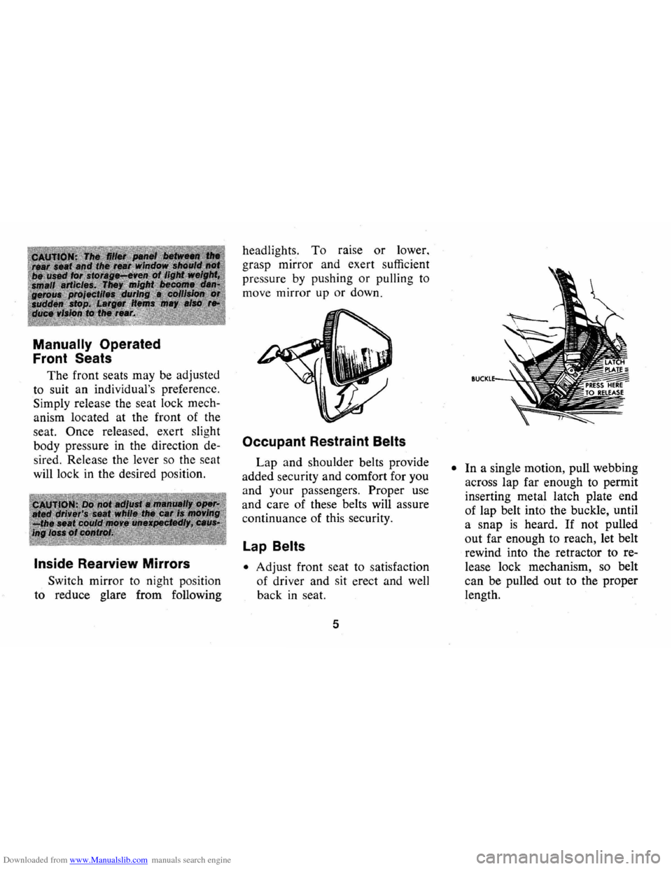
Switch mirror to night position
to reduce glare from following headlights.
To raise or lower,
grasp mirror and exert sufficient
pressure
by pushing or pulling to
move mirror up
or down.
Occupant Restraint Belts
Lap and shoulder belts provide
added security and comfort for you
and your passengers.
Proper use
and care of these belts will assure
continuance of this security.
Lap Belts
• Adjust front seat to satisfaction
of driver and sit erect and
well
back in seat.
5
• In a single motion, pull webbing
across lap far enough to permit
inserting metal latch plate end
of lap belt into the buckle, until
a snap
is heard. If not pulled
out far enough to reach, let belt
rewind into the retractor to re
lease lock mechanism, so belt
can be pulled out to the proper
length.
Page 9 of 84
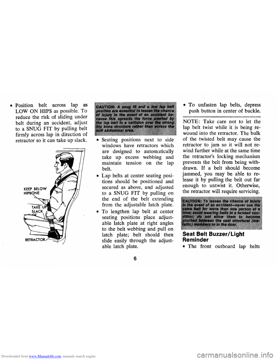
Downloaded from www.Manualslib.com manuals search engine • Position belt across lap as
LOW ON HIPS as possible. To
reduce the risk of sliding under
belt during an accident, adjust
to a
SNUG FIT by pulling belt
firmly across lap in direction
of
retractor so it can take up slack. • Seating posItIOns next to side
windows have retractors which
are designed to automatically
take up excess webbing and
maintain tension on the lap
belt.
• Lap belts at center seating posi
tions should be positioned and
secured as above, and adjusted
to a
SNUG FIT by pulling on
the end of the belt extending
from the adjustable latch plate.
• To lengthen lap belt at center
seating positions place adjust
able latch plate at right angles
to the belt webbing and pull on
latch plate; belt should then
slide easily through the adjust
able latch plate.
6
• To unfasten lap belts, depress
push button
in center of buckle.
NOTE: Take care not to let the
lap belt twist while it
is being re
wound into the retractor.
The bulk
of the twisted belt may cause the
retractor to jam so it will not re
wind further while at the same time
the retractor's locking mechanism
prevents the belt from being with
drawn.
If a belt should become
jammed, you may be able to re
lease
it by pulling the belt out far
enough to untwist it. Otherwise,
the retractor will require servicing.
Seat Belt Buzzer/Light
Reminder
• The front outboard lap belts
Page 16 of 84

Downloaded from www.Manualslib.com manuals search engine STEERING COLUMN CONTROLS
Anti-Theft Steering
Column Lock
The anti-theft lock, located on the
right side of the steering column,
has
five positions:
• Accessory -Permits operation
of electrical accessories when en
gine
is not running. To engage,
push key in and turn toward you
( counterclockwise) .
• Lock-Normal parking position.
Locks ignition and provides
added theft protection by pre
venting normal operation of
steering wheel and shift controls.
Key cannot be returned to
"lock"
position and removed until trans
mission is placed in "park"
(automatic transmission models)
or in reverse on manual trans
mission models.
• Off-Permits turning engine off
without locking steering wheel
and shift controls.
13
• Run -Normal operating posi
tion.
• Start -Permits engagement of
starter.
NOTE: The anti-theft steering column lock Is not a substitute lor the parking brake.
Always set the parking brake when leaving the car unattended.
PARKING
When leaving your car unattended,
• Place automatic transmission se
lector in Park (Reverse for man
ual transmission).
• Turn key to LOCK position.
• Set Parking brake.
• Remove key (the buzzer will re
mind you).
• Lock all doors.
Starting Engine
Automatic Transmission
Models
1. Apply the foot brake.
2. Place transmission selector
in "P" or "N" (UP" preferred).
Page 17 of 84
Downloaded from www.Manualslib.com manuals search engine A starter safety switch prevents
starter operation while the trans
mission selector
is in any drive
position.
(If it is necessary to
re-start the engine with the car
moving, place the selector lever
in
"N".)
3. Depress accelerator pedal and
activate starter as outlined be
low for different conditions.
• Cold Engine -Fully depress
accelerator pedal and slowly
release.
With foot off the
pedal,
crank the engine by
turning the ignition key to the
Start position -release when
engine starts.
If engine starts, but fails to
run, repeat this procedure.
When engine is running
smoothly (approximately 30
seconds), the idle speed may
be reduced by slightly depress
ing the accelerator pedal and
then slowly releasing.
• Warm Engine -Depress ac
celerator
pedal about halfway
and hold while cranking the
engine.
• Extremely Cold Weather
(Below
ODF.) Or After Car
14
Has Been Standing Idle
Several Days-
Fully depress and release ac
celerator pedal two
or three
times before cranking the en
gine.
With foot off the accel
erator pedal,
crank the engine
by turning the key to the
Start position and release
when engine starts .
Manual Transmission Models
1. Apply parking brake and shift
transmission to neutral.
2.
Hold clutch pedal to floor
throughout the starting proce
dure. A starter interlock prevents
starter operation when clutch
is
not fully depressed. (Select the
Page 20 of 84
Downloaded from www.Manualslib.com manuals search engine Driving with Manual Transmissions
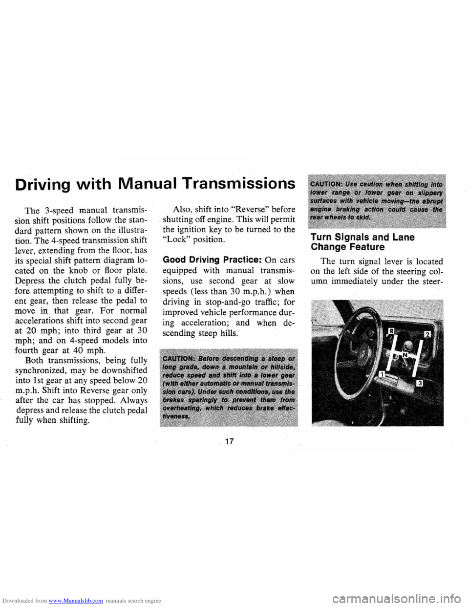
The 3-speed manual transmis
sion shift positions follow the stan
dard pattern shown on the illustra
tion. The 4-speed transmission shift
lever, extending from the floor, has
its special shift pattern diagram lo
cated on the knob or floor plate.
Depress the clutch pedal fully be
fore attempting to shift to a differ
ent gear, then release the pedal to
move in that gear.
For normal
accelerations shift into second gear
at 20 mph; into third gear at 30
mph; and on 4-speed models into
fourth gear at
40 mph.
Both transmissions , being fully
synchronized, may be downshifted
into 1 st gear at any speed below
20
m.p.h. Shift into Reverse gear only
after the car has stopped. Always
depress and release the clutch pedal
fully when shifting. Also,
shift into
"Reverse" before
shutting off engine. This will permit
the ignition key to be turned to the
"Lock" position.
Good Driving Practice: On cars
equipped with manual transmis
sions, use second gear at slow
speeds (less than
30 m.p.h.) when
driving in stop-and-go traffic; for
improved vehicle performance dur
ing acceleration; and when de
scending steep hills.
17
Turn Signals and Lane
Change Feature
The turn signal lever is located
on the left side of the steering col
umn immediately under the steer-
Page 28 of 84
Downloaded from www.Manualslib.com manuals search engine • Stopping distances may be
greater.
• Greater pedal effort may be re
quired .
• Pedal travel may be greater.
3.
Tryout brake operation by
starting and stopping on road
shoulder-then:
• If you judge such operation to
be safe, proceed cautiously at a
safe speed to nearest dealer for
repair.
• Or have car towed to dealer for
repair.
Continued operation of the car
in this condition
is dangerous.
Headlight Beam Indicator
Light
The headlights of your car have
high and low
beams to provide you with
proper night-time visibility
for most driving conditions. The
"low" beams are used during most
city driving. The
"high" beams are
especially useful when driving on
dark roads since
they' provide ex
cellent long range illumination.
The headlight beam indicator will
be on whenever the high beams
or
"brights" are in use. The Headlight
Beam Switch controls the headlight
beams (see Page
21).
Light Switch
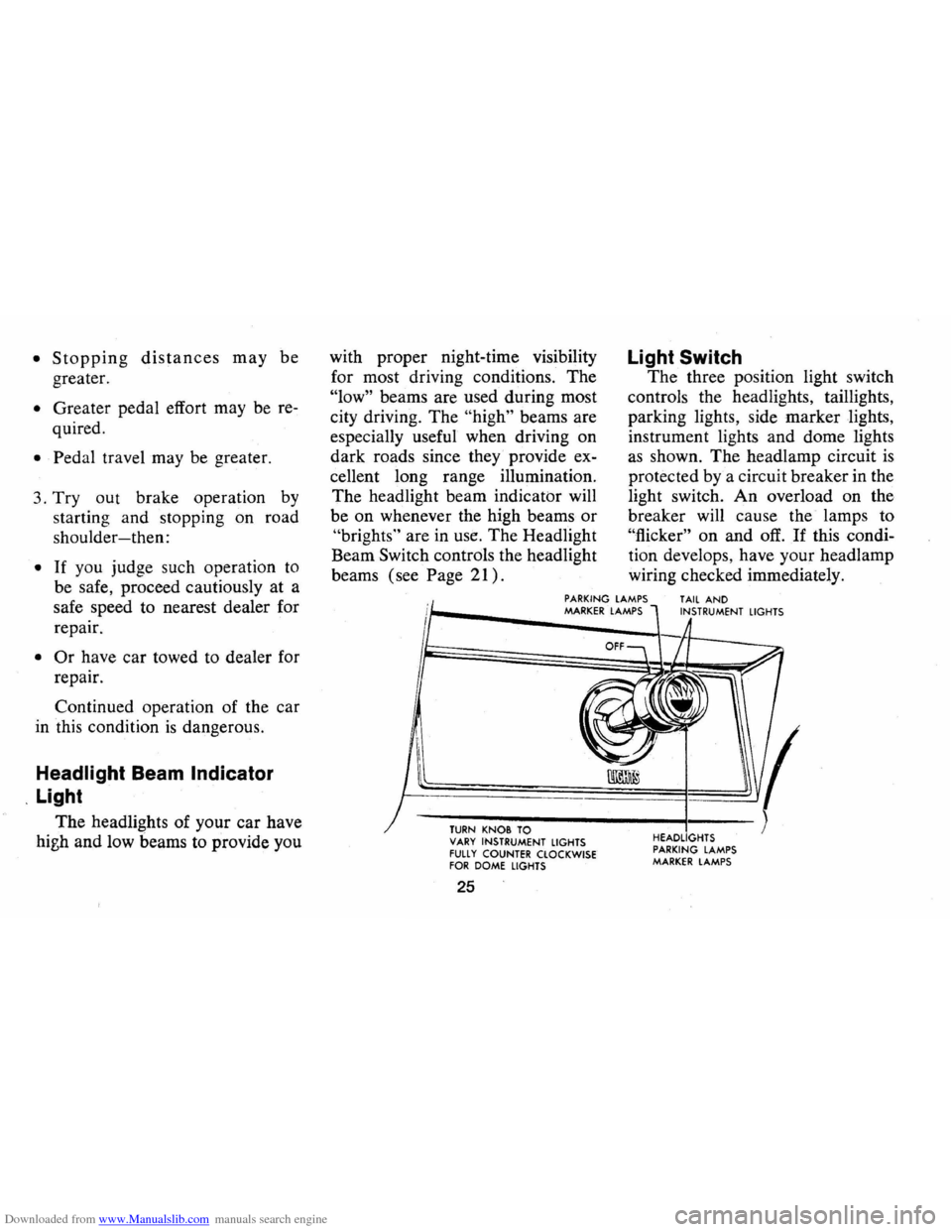
The three position light switch
controls the headlights, taillights,
parking lights, side marker lights,
instrument lights and dome lights
as shown. The headlamp circuit is
protected by a circuit breaker in the
light switch.
An overload on the
breaker will cause the lamps to
"flicker" on and off. If this condi
tion develops, have your headlamp
wiring checked immediately.
PARKING LAMPS MARKER LAMPS TAIL AND INSTRUMENT LIGHTS
TURN KN08 TO VARY INSTRUMENT LIGHTS FUll Y COUNTER CLOCKWISE FOR DOME LIGHTS
25
HEADLIGHTS
PARKING LAMPS MARKER LAMPS