1969 FORD MUSTANG kickdown
[x] Cancel search: kickdownPage 296 of 413
07-01-05
General Transmission Service
07-01-05
linkage may cause crossleakage and
subsequent transmission failure. Refer
to Linkage Adjustments in Part 7-2,
7-3 or 7-4 for detailed manual linkage
adjustment procedures.
CONTROL PRESSURE
CHECK
When the vacuum diaphragm unit is
operating properly and the downshift
linkage is adjusted properly, all the
transmission shifts (automatic and
kickdown) should occur within the
road speed limits specified in Part 7-5.
If the shifts do not occur within
limits or the transmission slips during
shift point, the following procedure is
suggested to determine engine, trans-
mission, linkage, vacuum diaphragm
unit or valve body problems.
1.
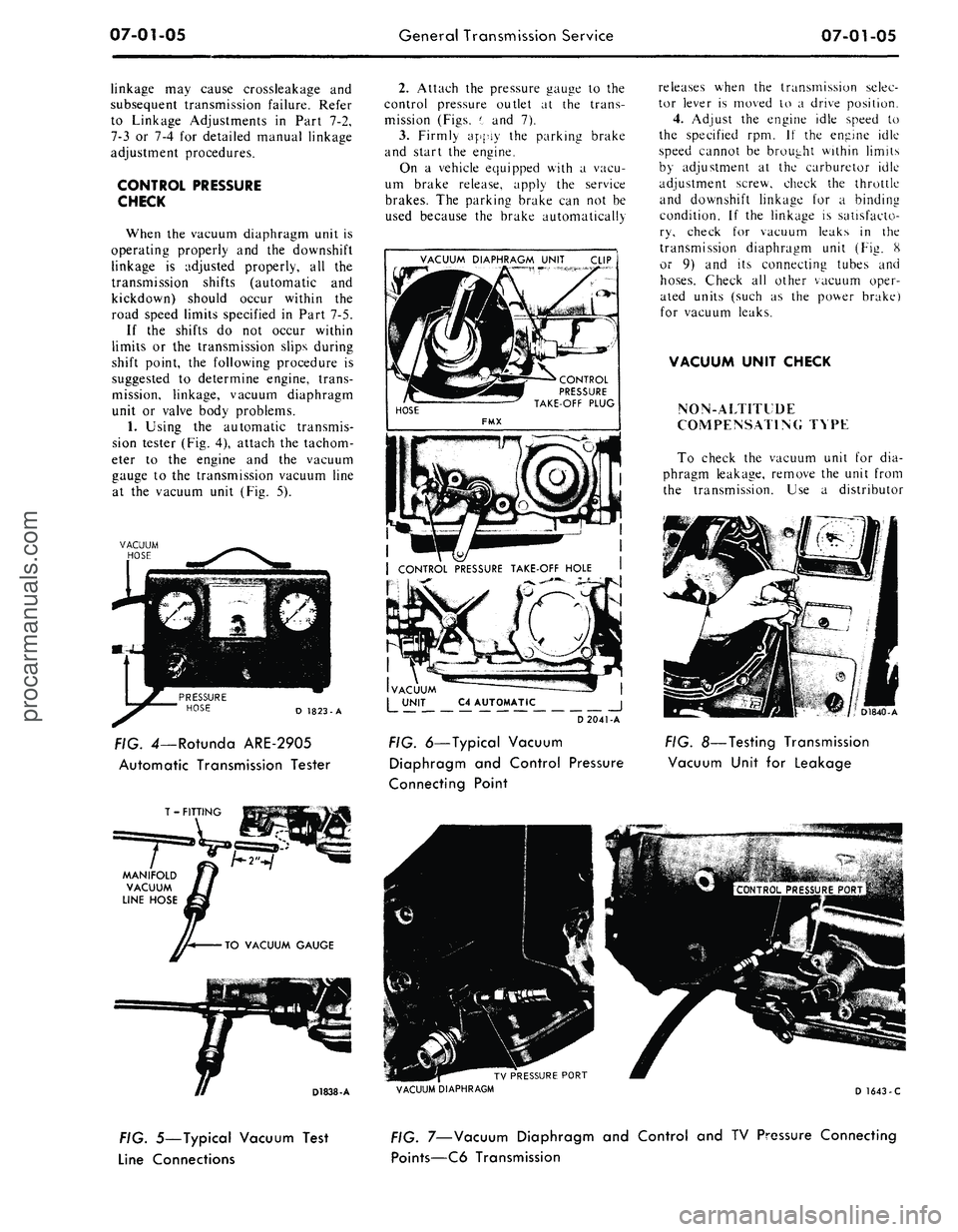
Using the automatic transmis-
sion tester (Fig. 4), attach the tachom-
eter to the engine and the vacuum
gauge to the transmission vacuum line
at the vacuum unit (Fig. 5).
D 1823-A
. 4—Rotunda ARE-2905
Automatic Transmission Tester
T - FITTING
2.
Attach the pressure gauge to the
control pressure outlet at the trans-
mission (Figs. '., and 7).
3.
Firmly apply the parking brake
and start the engine.
On a vehicle equipped with a vacu-
um brake release, apply the service
brakes. The parking brake can not be
used because the brake automatically
VACUUM DIAPHRAGM UNIT
CLIP
I
| CONTROL PRESSURE TAKE-OFF HOLE
D2041-A
FIG. 6—Typical Vacuum
Diaphragm and Control Pressure
Connecting Point
releases when the transmission selec-
tor lever is moved to a drive position.
4.
Adjust the engine idle speed lo
the specified rpm. If the engine idle
speed cannot be brought within limits
by adjustment at the carburetor idle
adjustment screw, check the throttle
and downshift linkage for a binding
condition. If the linkage is satisfacto-
ry, check for vacuum leaks in the
transmission diaphragm unit (Fig. 8
or 9) and its connecting tubes and
hoses.
Check all other vacuum oper-
ated units (such as the power brake)
for vacuum leaks.
VACUUM UNIT CHECK
NON-ALTITIDE
COMPENSATING TYPE
To check the vacuum unit for dia-
phragm leakage, remove the unit from
the transmission. Use a distributor
D1840-A
FIG. 8—Testing Transmission
Vacuum Unit for Leakage
VACUUM DIAPHRAGM
D 1643 -C
FIG. 5—Typical Vacuum Test
Line Connections
FIG.
7—Vacuum
Diaphragm and Control and TV Pressure Connecting
Points—C6 Transmissionprocarmanuals.com
Page 312 of 413
07-02-04
C4 Automatic Transmission
07-02-04
The transmission consists essentially
of a torque converter, planetary gear
train, two multiple disc clutches, a
one-way clutch and a hydraulic con-
trol system (Fig. 3).
The only adjustments on the trans-
mission proper are the intermediate
and low-reverse bands.
TRANSMISSION
MANUAL LEVER
2 IN-VEHICLE ADJUSTMENTS
AND
REPAIRS
CONTROL LINKAGE ADJUSTMENTS
The transmission control linkage
adjustments should be performed in
the order in which they appear in this
section of the manual.
THROTTLE AND DOWNSHIFT
LINKAGE ADJUSTMENTS
Adjusting the throttle linkage is im-
portant to be certain the throttle and
kickdown systems are properly adjust-
ed. The kickdown system should come
in when the accelerator is pressed
through detent, and not before detent.
Refer to Group 10 for detailed
throttle and downshift linkage adjust-
ment procedures.
MANUAL LINKAGE
ADJUSTMENTS
Column Shift
1.
Place the selector lever in the D
position tight against the D stop.
2.
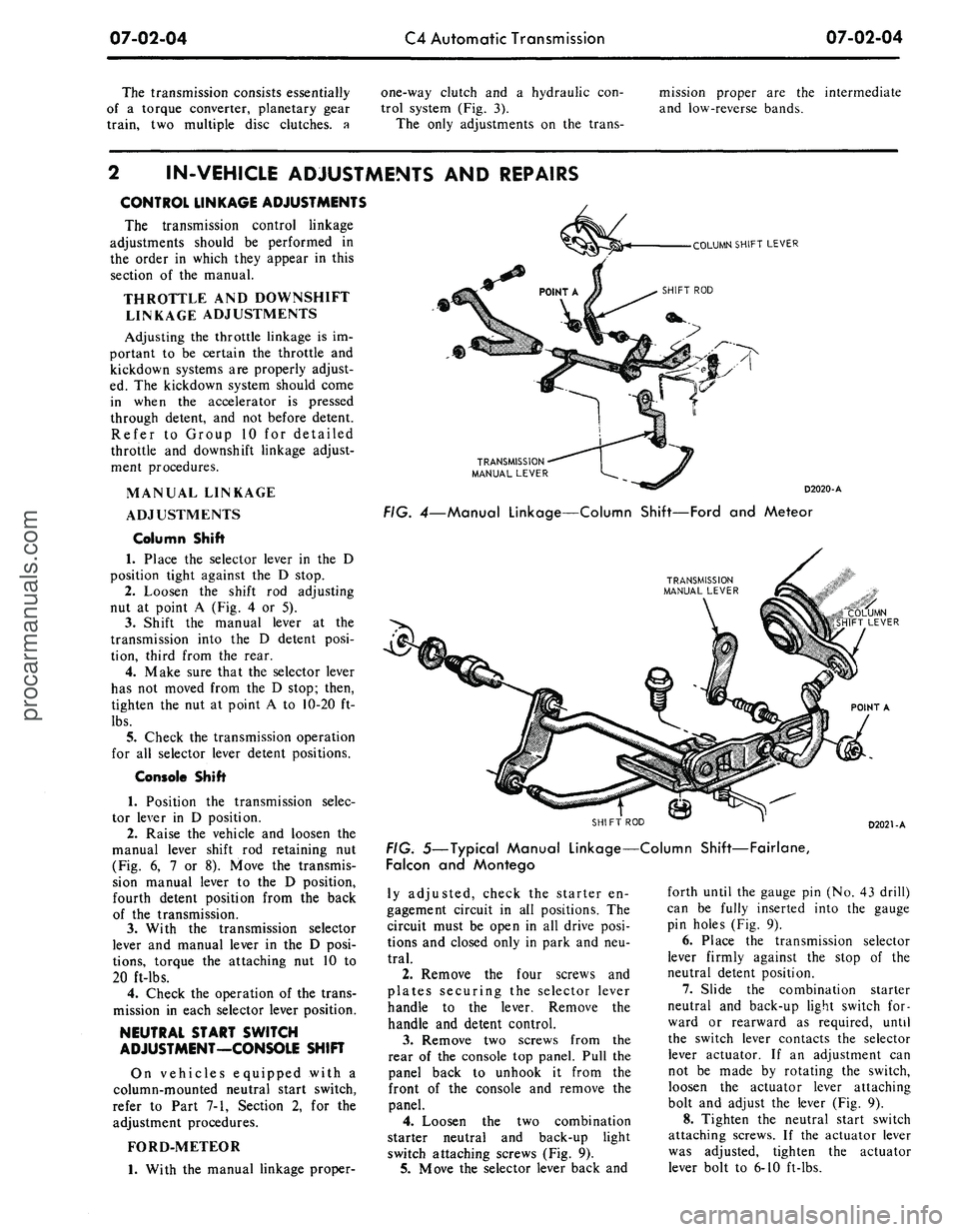
Loosen the shift rod adjusting
nut at point A (Fig. 4 or 5).
3.
Shift the manual lever at the
transmission into the D detent posi-
tion, third from the rear.
4.
Make sure that the selector lever
has not moved from the D stop; then,
tighten the nut at point A to 10-20 ft-
lbs.
5.
Check the transmission operation
for all selector lever detent positions.
Console Shift
1.
Position the transmission selec-
tor lever in D position.
2.
Raise the vehicle and loosen the
manual lever shift rod retaining nut
(Fig. 6, 7 or 8). Move the transmis-
sion manual lever to the D position,
fourth detent position from the back
of the transmission.
3.
With the transmission selector
lever and manual lever in the D posi-
tions,
torque the attaching nut 10 to
20 ft-lbs.
4.
Check the operation of the trans-
mission in each selector lever position.
NEUTRAL START SWITCH
ADJUSTMENT—CONSOLE SHIFT
On vehicles equipped with a
column-mounted neutral start switch,
refer to Part 7-1, Section 2, for the
adjustment procedures.
FORD-METEOR
1.
With the manual linkage proper-
COLUMN SHIFT LEVER
D2020-A
FIG.
4—Manual
Linkage—Column Shift—Ford
and
Meteor
"COLUMN
SHIFT LEVER
POINT
A
SHIFT
ROD
D2021-A
FIG.
5—Typical
Manual Linkage—Column
Shift—Fairlane,
Falcon
and
Montego
ly adjusted, check the starter en-
gagement circuit in all positions. The
circuit must be open in all drive posi-
tions and closed only in park and neu-
tral.
2.
Remove the four screws and
plates securing the selector lever
handle to the lever. Remove the
handle and detent control.
3.
Remove two screws from the
rear of the console top panel. Pull the
panel back to unhook it from the
front of the console and remove the
panel.
4.
Loosen the two combination
starter neutral and back-up light
switch attaching screws (Fig. 9).
5.
Move the selector lever back and
forth until the gauge pin (No. 43 drill)
can be fully inserted into the gauge
pin holes (Fig. 9).
6. Place the transmission selector
lever firmly against the stop of the
neutral detent position.
7.
Slide the combination starter
neutral and back-up light switch for-
ward or rearward as required, until
the switch lever contacts the selector
lever actuator. If an adjustment can
not be made by rotating the switch,
loosen the actuator lever attaching
bolt and adjust the lever (Fig. 9).
8. Tighten the neutral start switch
attaching screws. If the actuator lever
was adjusted, tighten the actuator
lever bolt to 6-10 ft-lbs.procarmanuals.com
Page 344 of 413

07-03-04
FMX Transmission
07-03-04
FORWARD
CLUTCH
REVERSE-HIGH
CLUTCH
' INTERMEDIATE SERVO
3-2 KICKDOWN
CONTROL VALVE
RELEASE
APPLY
LOW REVERSE
SERVO
ORIFICE
LOW SERVO
LOCKOUT
VALVE
2-3 SHIFT VALVE
AND THROTTLE
REDUCING VALVE
1-2 SHIFT
ACCUMULATOR
VALVE
CHECK BALL
USED IN PHD
MODEL
TRANSMISSIONS
ONLY
LOW SERVO
MODULATOR
VALVE
GOVERNOR
CONTROL PRESSURE
REGULATOR VALVE
FRONT PUMP
THROTTLE
BOOST VALVE
OIL
SCREEN
CONVERTER
CONVERTER
PRESSURE
REGULATOR
VALVE
THROTTLE
BOOST VALVE
POLICE
AND
TAXI,
ONLY
COOLER RETURN
OIL CHECK
VALVE
REAR
LUBE
OIL
COOLER
X EXHAUST
D 2047-A
FIG.
3—Hydraulic
Control System—FMX Transmissionprocarmanuals.com
Page 345 of 413
07-03-05
FMX Transmission
07-03-05
IN-VEHICLE ADJUSTMENTS AND REPAIRS
CONTROL LINKAGE
ADJUSTMENTS
The transmission control linkage
adjustments should be performed in
the order in which they appear in this
section of the manual.
THROTTLE AND
DOWNSHIFT LINKAGE
ADJUSTMENTS
Adjusting the throttle linkage is im-
portant to be certain the throttle and
kickdown systems are properly adjust-
ed. The kickdown system should come
in when the accelerator is pressed
through detent, and not before detent.
Refer to Group 10 for detailed
throttle and downshift linkage adjust-
ment procedures.
MANUAL LINKAGE
ADJUSTMENT
COLUMN SHIFT
1.
Place the selector lever in the D
position tight against the stop.
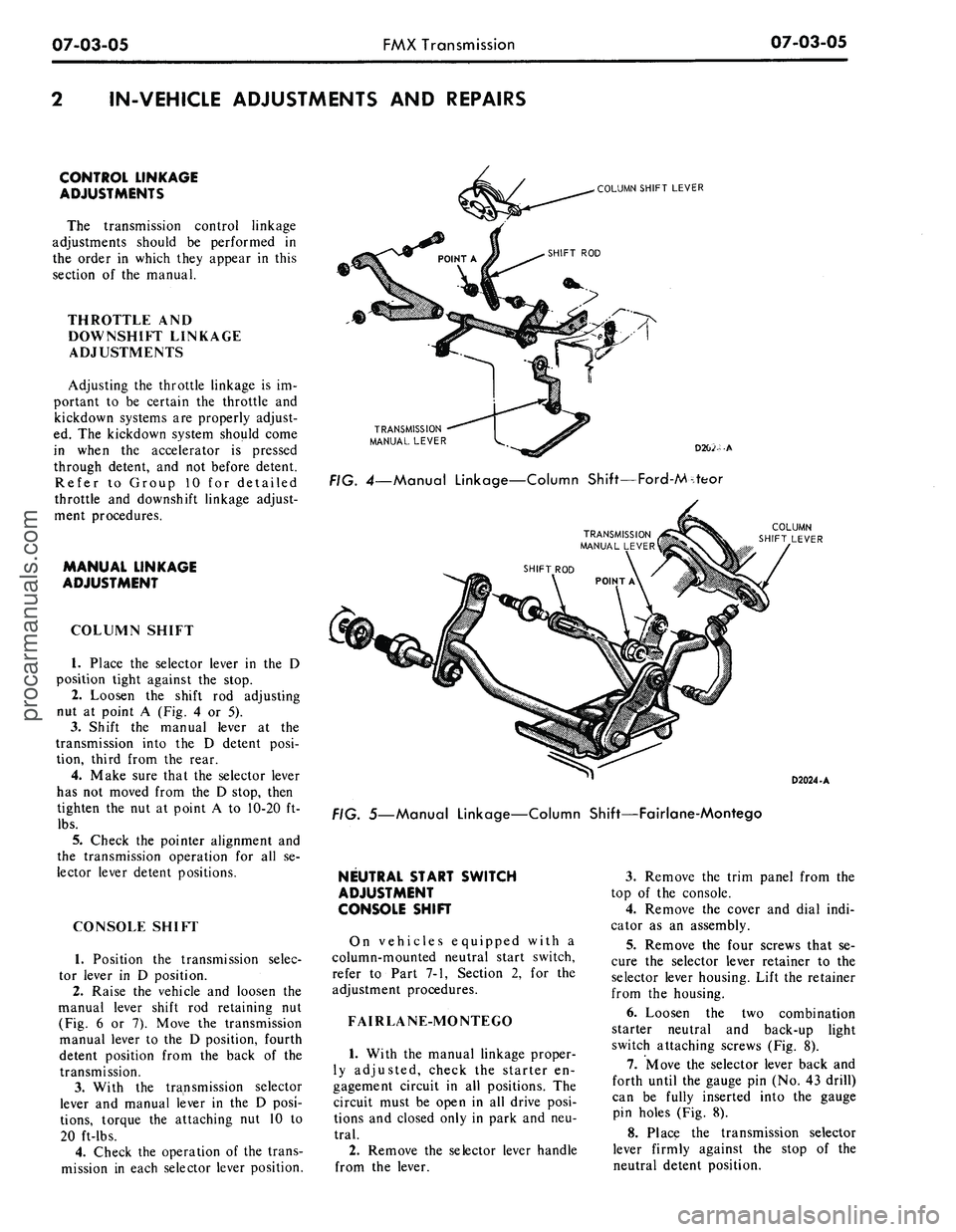
2.
Loosen the shift rod adjusting
nut at point A (Fig. 4 or 5).
3.
Shift the manual lever at the
transmission into the D detent posi-
tion, third from the rear.
4.
Make sure that the selector lever
has not moved from the D stop, then
tighten the nut at point A to 10-20 ft-
lbs.
5.
Check the pointer alignment and
the transmission operation for all se-
lector lever detent positions.
CONSOLE SHIFT
1.
Position the transmission selec-
tor lever in D position.
2.
Raise the vehicle and loosen the
manual lever shift rod retaining nut
(Fig. 6 or 7). Move the transmission
manual lever to the D position, fourth
detent position from the back of the
transmission.
3.
With the transmission selector
lever and manual lever in the D posi-
tions,
torque the attaching nut 10 to
20 ft-lbs.
4.
Check the operation of the trans-
mission in each selector lever position.
COLUMN SHIFT LEVER
€>
TRANSMISSION
MANUAL LEVER
FIG. 4—Manual Linkage—Column Shift—Ford-Mteor
D2024-A
FIG. 5—Manual Linkage—Column Shift—Fairlane-Montego
NEUTRAL START SWITCH
ADJUSTMENT
CONSOLE SHIFT
On vehicles equipped with a
column-mounted neutral start switch,
refer to Part 7-1, Section 2, for the
adjustment procedures.
FAIRLANE-MONTEGO
1.
With the manual linkage proper-
ly adjusted, check the starter en-
gagement circuit in all positions. The
circuit must be open in all drive posi-
tions and closed only in park and neu-
tral.
2.
Remove the selector lever handle
from the lever.
3.
Remove the trim panel from the
top of the console.
4.
Remove the cover and dial indi-
cator as an assembly.
5.
Remove the four screws that se-
cure the selector lever retainer to the
selector lever housing. Lift the retainer
from the housing.
6. Loosen the two combination
starter neutral and back-up light
switch attaching screws (Fig. 8).
7.
Move the selector lever back and
forth until the gauge pin (No. 43 drill)
can be fully inserted into the gauge
pin holes (Fig. 8).
8. Place the transmission selector
lever firmly against the stop of the
neutral detent position.procarmanuals.com
Page 374 of 413

07-04-05
C-6 Automatic Transmission
07-04-05
IN-VEHICLE ADJUSTMENTS AND REPAIRS
CONTROL LINKAGE
ADJUSTMENTS
The transmission control linkage
adjustments should be performed in
the order in which they appear in this
section of the manual.
THROTTLE AND
DOWNSHIFT LINKAGE
ADJUSTMENTS
Adjusting the throttle linkage is im-
portant to be certain the throttle and
kickdown systems are properly adjust-
ed. The kickdown system should come
in when the accelerator is pressed
through detent, and not before detent.
Refer to Group 10 for detailed
throttle and downshift linkage adjust-
ment procedures.
MANUAL LINKAGE
ADJUSTMENT
Column Shift
1.
Place the selector lever in the D
position tight against the stop.
2.
Loosen the shift rod adjusting
nut at point A (Fig. 4, 5, 6 or 7).
3.
Shift the manual lever at the
transmission into the D detent posi-
tion, third from the rear.
4.
Make sure that the selector lever
has not moved from the D stop; then,
tighten the nut at point A to 10-20 ft-
lbs.
5.
Check the transmission operation
for all selector lever detent positions.
Console Shift
1.
Position the transmission selec-
tor lever in the D position.
2.
Raise the vehicle and loosen the
manual lever shift rod retaining nut
(Fig. 8, 9 or 10). Move the transmis-
sion manual lever to the D position,
fourth detent position from the back
of the transmission.
3.
With the transmission selector
lever and manual lever in the D posi-
tions,
torque the retaining nut 10 to
20 ft-lbs.
4.
Check the operation of the trans-
mission in each selector lever position.
COLUMN SHIFT LEVER
SHIFT ROD
TRANSMISSION
MANUAL LEVER
D2031-A
FIG. 4—Manual Linkage—Column Shift—Ford-Mercury-Meteor
TRANSMISSION
MANUAL LEVER
FIG. 5—Manual Linkage—Column Shift—Fairlane-Montego
NEUTRAL START SWITCH
ADJUSTMENT-
CONSOLE SHIFT
On vehicles equipped with a
column-mounted neutral start switch,
refer to Part 7-1, Section 2, for the
adjustment procedures.
FORD, MERCURY
AND METEOR
1.
With the manual linkage proper-
ly adjusted, check the starter en-
gagement circuit in all positions. The
circuit must be open in all drive posi-
tions and closed only in park and neu-
tral.
2.
Remove the four screws and
plates securing the selector lever
D2032-M
the
handle to the lever. Remove
handle and detent control.
3.
Remove the two screws from the
rear of the console top panel. Pull the
panel back to unhook it from the
front of the console and remove the
panel.
4.
Loosen the two combination
starter neutral and back-up light
switch attaching screws (Fig. 11).
5.
Move the selector lever back and
forth until the gauge pin (No. 43 drill)
can be fully inserted into the gauge
pin holes (Fig. 11).
6. Place the transmission selector
lever firmly against the stop of the
neutral detent position.
7.
Slide the combination starter
neutral and back-up light switch for-
ward or rearward as required, untilprocarmanuals.com