1967 CHEVROLET CAMARO engine
[x] Cancel search: enginePage 317 of 659

ENGINE FUEL 6M-9
4.
Wash body with cleaning solvent and wip dry.
5. Wash filter element by sloshing up and down in
cleaning solvent.
6. Dry filter unit with an air hose or let stand until
dry.
7. Fill body of cleaner to full mark with SAE 50 engine
oil. If expected temperatures are to be consistently
below freezing, use SAE 20 engine oil.
8. Assemble filter and cover assembly to body of
cleaner.
9. Install cleaner, making sure it fits tight and is set
down securely. \
OIL
WETTED
PAPER
ELEMENT
Replacement
1.
Remove wing nut, washer and cover.
2.
Remove paper element and discard.
3.
Remove bottom section of air cleaner and gasket
on air horn of carburetor. Discard air horn gasket.
4.
Clean bottom section of air cleaner and cover pieces
thoroughly, to remove dust and grime.
NOTE:
Check bottom section of air cleaner
seal for tears or cracks.
5. Install a new gasket on carburetor air horn and set
bottom section of air cleaner on carburetor.
6. Install new paper element on bottom section of air
cleaner with either end up.
NOTE:
Plastisol seal is the same material on
both ends.
7. Install cover, washer and wing nut.
Testing (Fig. 5A)
Tool J-7825, is designed to check paper element air
cleaners to determine whether the element has ma-
terially decreased in efficiency arid should be replaced
or has only slightly increased air restriction and is
suitable for further service. In combination with a
tachometer, this instrument will quickly and accurately
determine the air cleaner element condition.
VENT HOLE
TOWARD DASH
NOTE:
t Before testing, inspect for holes or
breaks in the element, as these defects re-
quire immediate replacement. If no holes or
breaks exist, proceed as follows:
1.
Remove all hoses and plug all openings except air
cleaner inlet.
2.
Install air cleaner, using Tool J-7825 in place of the
wing nut. Screw Tool J-7825 onto the stud until it
seals tightly against the air cleaner cover. Rotate
the entire tool so that the scale can be read from
the left side of the car. Be sure the vent hole is
toward the dash.
3.
Connect a tachometer and place it so that it may be
read simultaneously with Tool J-7825.
4.
Zero oil level in the inner tube by pulling inner tube
upward until the rubber seal is above the vent hole,
then raise or lower as' required until the inner tube
oil level is exactly to the "0" mark.
5. Start engine. If engine is cold, allow to run for 2 to
3 minutes. The automatic choke must be fully open.
6. Accelerate the engine slowly until the inner tube oil
level of Tool J-7825 just reaches the 1/4 mark.
Allow engine speed to stabilize and note tachometer
(rpm) reading. Decelerate engine.
7. If the tachometer reading is at or below the follow-
ing, the oil wetted paper air cleaner element is re-
stricted beyond the allowable limit and should be
replaced. If testing indicates that the element
restriction is satisfactory at 12,000 miles, the ele-
ment need not be replaced but should be retested
every 6,000 miles thereafter until replaced.
Engine
Displacement
283 cu.
in.
327 cu.
in.
350 cu. in.
396 cu.
in.
427 cu.
in.
Horsepower
195
210
275
300
325
350
295
325
350
385
390
425
Minimum
Allowable
RPM
2300
2100
210Q
2600
2600
1550
1950
1850
1850
2140
Fig.
5A—Testing Air Cleaner
8. Remove tachometer and Tool J-7825 from vehicle
and push down inner tube until seal is below vent
hole to prevent oil loss.
Tool J-7825
FiHing
Tool
Tool J-7825 is shipped dry and must be filled with the
red gauge oil (specific gravity .826) provided.
Pull the knurled inner tube completely out of the gauge
and add oil to the reservoir until the oil level is between
CHEVROLET CHASSIS SERVICE /MANUAL
Page 318 of 659

ENGINE FUEL
6M-10
the
two
"FILL71 lines
(fig.
6A). Refill whenever
the
level
falls below the lower
<'FILL"
line.
Storing Tool
When
the
tool
is
not used, fully depress
the
inner tube.
This seals
off
the
oil
reservoir from the vent hole
to pre-
vent
oil
loss
if
the tool
is
tipped.
Fig. 6A-Filling Tool with
Oil
FUEL PUMP
INDEX
Page
General Description
. . . . 6M-10
Service Procedures .6M-10
Inspection .6M-10
Page
Test
. . ; 6M-10
Removal
6M-11
Installation
6M-11
GENERAL DESCRIPTION
The fuel pump
(fig. IP)
used
on all
Chevrolet vehicles
covered
in
this manual
are of the
diaphragm type.
The
pumps
are
actuated
by an
eccentric located on
the
engine
camshaft.
On
in-line engines,
the
eccentric actuates
the
rocker arm*
On V-8
engines,
a
push
rod
(located be-
tween
the
camshaft eccentric and fuel pump) actuates
the
pump rocker
arm.
Because
of
design, this pump
is
serviced
as an
assembly only.
Fig.
IP—Fuel Pump (Non-Serviceable)
SERVICE PROCEDURES
Inspection
The fuel pump should
be
checked
to
make sure
the
mounting bolts
and
inlet and outlet connections
are
tight.
Test
Always test pump while
it is
mounted on the engine
and
be sure there
is
gasoline
in
the tank.
The line from
the
tank
to the
pump
is the
suction side
of
the
system and the line from the pump
to the
carbure-
tor
is the
pressure side
of the
system.
A
leak on
the
pressure side, therefore, would
be
made apparent
by
CHEVROLET CHASSIS SERVICE MANUAL
Page 319 of 659

ENGINE FUEL 6M-11
dripping fuel, but a leak on the suction would not be ap-
parent except for its effect of reducing volume of fuel on
the pressure side.
1.
Tighten any loose line connections and look for bends
or kinks in lines.
2.
Disconnect fuel pipe at carburetor. Disconnect dis-
tributor to coil primary wire so that engine can be
cranked without firing. Place suitable container at
end of pipe and crank engine a few revolutions. If
little or no gasoline flows from open end of pipe then
fuel pipe is clogged or pump is inoperative. Before
removing pump disconnect fuel pipe at gas tank and
outlet pipe and blow through them with an air hose
to make sure they are clear. Reconnect pipes and
retest while cranking engine.
CAUTION: Whenever the engine is cranked re-
motely at the starter, with a special jumper
cable or other means, the primary distributor
lead must be disconnected from the negative
post on the coil and the ignition switch must be
in the "ON" position. Failure to do this will
result in a damaged grounding circuit in the
ignition switch.
3.
If fuel flows from pump in good volume from pipe
at carburetor, check fuel delivery pressure to be
certain that pump is operating withint specified limits
as follows:
a. Attach a fuel pump pressure test gauge to dis-
connect end of pump to carburetor pipe.
b.
Run engine at approximately 450-1,000 rpm (on
gasoline in carburetor bowl) and note reading on
pressure gauge.
c. If pump is operating properly the pressure will
be within specifications and will remain constant
at speeds between 450-1,000 rpm. If pressure
is too low, too high, or varies materially at dif-
ferent speeds, the pump should be replaced.
Removal
1.
Disconnect fuel inlet and outlet pipes at fuel pump.
Fig.
2P-Installing 283, 327, 350 V8 Engine Fuel Pump
2.
Remove fuel pump mounting bolts and remove pump
and gasket.
3.
On V8 engines; if push rod is to be removed, remove
pipe plug then remove push rod (396 and 427 cu. in.
engines), remove fuel pump adapter and gasket then
remove push rod (283 and 327 cu. in. engines).
4.
If a new fuel pump is to be installed, transfer
fittings.
Installation
1.
On V8 engines; if removed, install fuel pump push
rod and pipe fitting or fuel pump adapter. Use.
gasket sealer on gasket or pipe fitting.
2.
Install fuel pump using a new gasket and tighten
securely. Use sealer on fuel pump mounting bolt
threads.
NOTE:
On V8 engines, a pair of mechanical
fingers may be used to hold fuel pump push rod
up while installing fuel pump (fig. 2P).
3.
Connect fuel pipes to pump.
4.
Start engine and check for leaks.
CHEVROLET CHASSIS SERVICE MANUAL
Page 320 of 659

ENGINE FUEL
6M-12
SPECIAL TOOLS
—1137
J-4552
J-5496,
J-7825
15
J-6058A
BENDING
TOOLS
J-5197
J-6556
J-9789
J-8328
Fig.
lT-Engine Fuel Special Tools
CHEVROLET CHASSIS SERVICE MANUAL
Page 321 of 659

SECTION 6T
AIR INJECTION REACTOR SYSTEM
INDEX
Page
General Description 6T-1
Maintenance Procedures 6T>1
Drive Belt. ...-..' 6T-1
Inspection 6T-1
, Adjustment . . 6T-1
Replacement 6T-1
Drive Pulley . . . . 6T-1
Replacement 6T-1
Pump Pulley ....................... 6T-1
Replacement. 6T-1
Air Manifold, Hose and Tube
...........>*.
6T-2
Inspection . . 6T-2
Replacement 6T-2
Check Valve (s) 6T-3
Page
Inspection 6T-3
Replacement . . 6T-3
Mixture Control Valve 6T-3
Inspection 6T-3
Replacement 6T-3
Air Injection Tube 6T-4
Inspection . . . ... . . . .... 6T-4
Replacement 6T-4
Air Injection Pump 6T-4
Inspection 6T-4
Replacement . 6T-4
Pressure Relief Valve Replacement 6T-4
Special Tools 6T-5
GENERAL
The Air Injection Reactor (A.I.R.) System (fig. 1) con-
sists of: the air injection pump (with necessary brackets
and drive attachments), air injection tubes (one for each
cylinder), a mixture control valve, check valves (one for
In Line engines, two for V8 engines) and air manifold as-
semblies, tubes and hoses necessary to connect the
various components.
Carburetors and distributors for engines with the
A.I.R. System are designed, particularly, for these en-
gines;
therefore, they should not be interchanged with or
replaced by a carburetor or distributor designed for an
engine without the A.I.R. System.
The air injection pump (fig. 2) picks up fresh filtered
air from the air cleaner, compresses the air and injects
it through the air manifolds, hoses and injection tubes
into the exhaust system in the area of the exhaust valves.
The fresh air ignites and burns the unburned portion of
the exhaust gases in the exhaust system, thus minimizing
exhaust contamination.
The mixture control valve (fig. 3) when triggered by a
sharp increase in manifold vacuum, supplies the intake
manifold with fresh filtered air to lean out the fuel-air
DESCRIPTION
mixture and prevent exhaust system backfire.
The check valve(s) prevent exhaust gases from entering
and damaging the air injection pump, as back flow can
occur even under normal operating conditions.
When properly installed and maintained, the A.I.R.
System will keep exhaust emissions well below require-
ments. However, if any A.I.R. component or any engine
component that operates in conjunction with the A.I.R.
system should malfunction, the exhaust emissions might
be increased.
Because of the relationship between "Engine Tune
Up"
and "Unburned Exhaust Gases", the condition of
Engine Tune Up should be checked whenever the A.I.R.
System seems to be malfunctioning. Particular care
should be taken in checking items that affect fuel - air
ratio such as the crankcase ventilation system, the
carburetor and the carburetor air cleaner.
Because of the similarity of many parts, typical illus-
trations and procedures are used except where specific
illustrations or procedures are necessary to clarify the
operation. For Repair Procedures on the Air Injection
Pump,
refer to the Passenger Chassis Overhaul Manual.
MAINTENANCE PROCEDURES
Drive Belt
Inspection
• Inspect drive belt for wear, cracks or deterioration
and replace if required.
• Inspect belt tension and adjust if below 50 lb. using a
strand tension gauge.
Adjustment
• Loosen pump mounting bolt and pump adjustment
bracket bolt.
• Move pump until belt is tight (55±5 lb. used belt or
75±5 lb. new belt using a strand tension gauge) then
tighten adjustment bracket bolt and mounting bolt.
CAUTION: Do not pry on the pump housing.
Distortion of the housing will result in extensive
damage to the Air Injection Pump.
Replacement
• Loosen pump mounting bolt and pump adjustment
bracket bolt then swing pump until drive belt may be
removed.
• Install a new drive belt and adjust as outlined above.
Drive Pulley .
Replacement
• Remove drive belt as outlined above then replace
drive pulley.
• Install and adjust drive belt as outlined above.
Pump Pulley
Replacement
• Hold pump pulley from turning by compressing drive
belt then loosen pump pulley bolts.
• Remove drive belt as outlined above then remove
pump pulley.
• Install pump pulley with retaining bolts hand tight.
CHEVROLET CHASSIS SERVICE MANUAL
Page 323 of 659

AIR INJECTOR REACTOR SYSTEM
6T-3
MIXTURE
CONTROL
VALVE
SIGNAL
PUMP PRESSURE
(MIXTURE VALVE INLET)
PUMP PRESSURE
(AIR MANIFOLD INLET)
IN LINE
AIR INJECTION
PUMP INLET
MIXTURE
CONTROL
VALVE
SIGNAL
MIXTURE
CONTROL
VALVE
OUTLET
MIXTURE
CONTROL
VALVE
INLET
AIR INJECTION
PUMP INLET
V8 (TYPICAL)
PUMP PRESSURE
(AIR MANIFOLD INLET)
MIXTURE CONTROL
VALVE INLET
MIXTURE CONTROL
VALVE SIGNAL
AIR INJECTION
PUMP INLET
PUMP PRESSURE^
(AIR MANIFOLD
J
MIXTURE CONTROL
VALVE OUTLET
V8 (396-427)
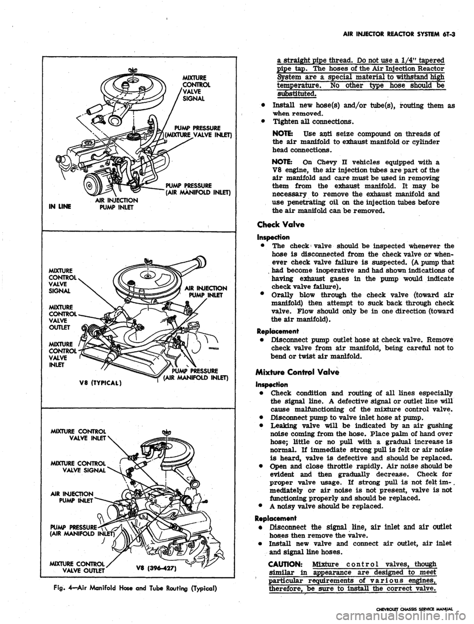
Fig.
4—Air Manifold Hose and Tube Routing (Typical)
a straight pipe thread.
Do
not use
a 1/4"
tapered
pipe
tap. The
hoses
of
the
Air
Injection Reactor
System
are a
special material
to
withstand high
temperature.
No
other type hose should
be
substituted.
• Install
new
hose(s) and/or tube(s), routing them
as
when removed.
• Tighten
all
connections.
NOTE:
Use
anti seize compound
on
threads
of
the
air
manifold
to
exhaust manifold
or
cylinder
head connections.
NOTE:
On
Chevy
n
vehicles equipped with
a
V8 engine,
the air
injection tubes
are
part
of the
air manifold
and
care must
be
used
in
removing
them from
the
exhaust manifold.
It may be
necessary
to
remove
the
exhaust manifold
and
use penetrating
oil on the
injection tubes before
the
air
manifold can
be
removed.
Check Valve
Inspection
•
The
check valve should
be
inspected whenever
the
hose
is
disconnected from
the
check valve
or
when-
ever check valve failure
is
suspected. (A pump that
,
had
become inoperative and had shown indications
of
having exhaust gases
in the
pump would indicate
check valve failure)..
• Orally blow through
the
check valve (toward
air
manifold) then attempt
to
suck back through check
valve. Flow should only
be in one
direction (toward
the
air
manifold).
Replacement
• Disconnect pump outlet hose
at
check valve. Remove
check valve from
air
manifold, being careful not
to
bend
or
twist
air
manifold.
Mixture Control Valve
Inspection
• Check condition
and
routing
of all
lines especially
the signal line.
A
defective signal
or
outlet line will
cause malfunctioning
of the
mixture control valve.
• Disconnect pump
to
valve inlet hose
at
pump.
• Leaking valve will
be
indicated
by an air
gushing
noise coming from
the
hose. Place palm
of
hand over
hose; little
or no
pull with
a
gradual increase
is
normal.
If
immediate strong pull
is
felt
or air
noise
is heard, valve
is
defective
and
should
be
replaced.
• Open
and
close throttle rapidly.
Air
noise should
be
evident
and
then gradually decrease. Check
for
proper valve usage.
If
strong pull
is not
felt
im-.
mediately
or air
noise
is not
present, valve
is not
functioning properly and should be replaced.
•
A
noisy valve should be replaced.
Replacement
• Disconnect
the
signal line,
air
inlet
and air
outlet
hoses then remove
the
valve.
• Install
new
valve
and
connect
air
outlet,
air
inlet
and signal line hoses.
CAUTION: Mixture control valves, though
similar
in
appearance
are
designed
to
meet
particular requirements
of
various engines,
therefore,
be
sure
to
install
the
correct valve.
CHEVROLET CHASSIS SERVICE MANUAL
Page 324 of 659

AIR INJECTOR REACTOR SYSTEM 6T-4
Air injection Tube
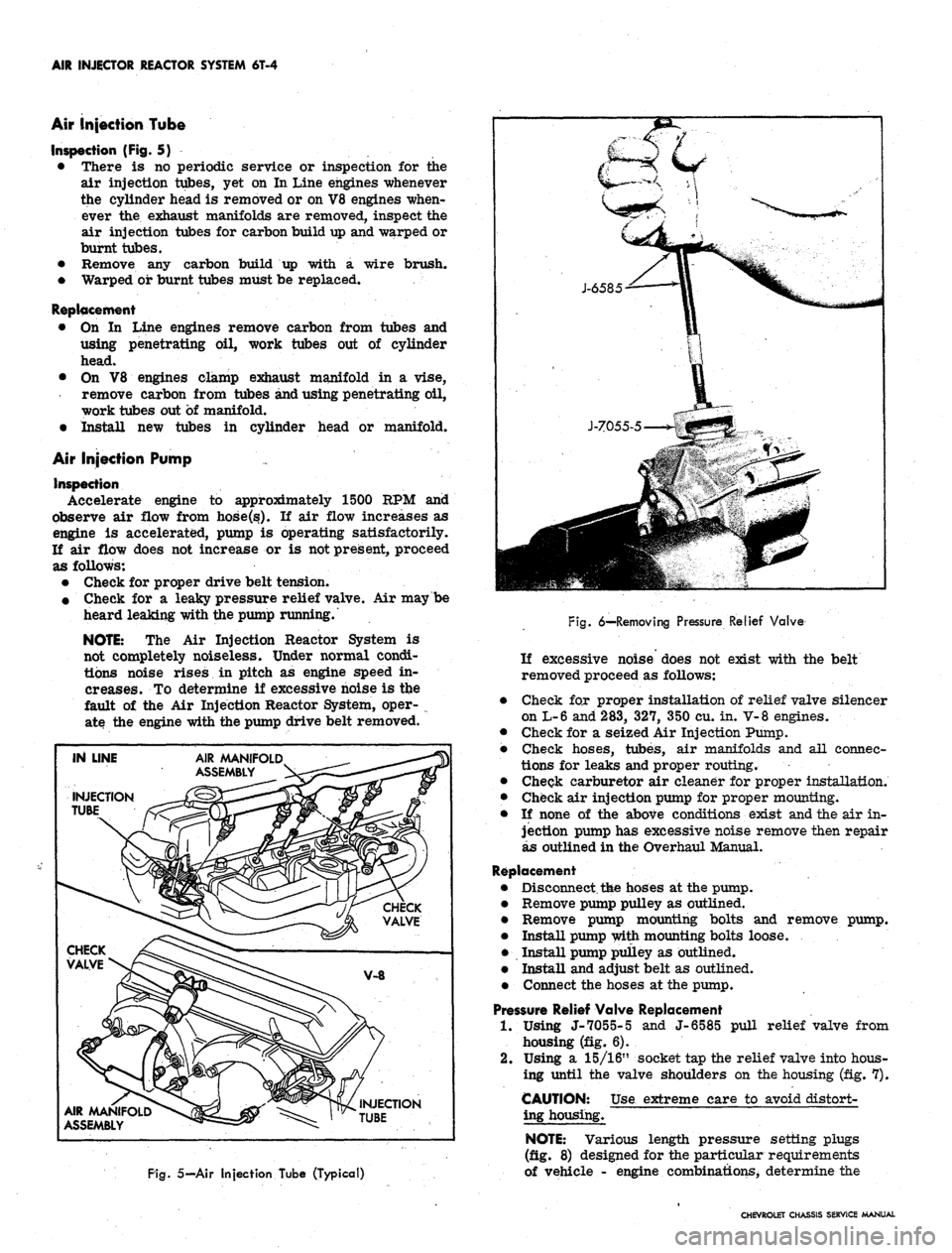
Inspection (Fig. 5)
• There is no periodic service or inspection for the
air injection tubes, yet on In Line engines whenever
the cylinder head is removed or on V8 engines when-
ever the exhaust manifolds are removed, inspect the
air injection tubes for carbon build up and warped or
burnt tubes.
• Remove any carbon build up with a wire brush.
• Warped or burnt tubes must be replaced.
Replacement
• On In Line engines remove carbon from tubes and
using penetrating oil, work tubes out of cylinder
head.
• On V8 engines clamp exhaust manifold in a vise,
remove carbon from tubes and using penetrating oil,
work tubes out of manifold.
• Install new tubes in cylinder head or manifold.
Air Injection Pump
Inspection
Accelerate engine to approximately 1500 KPM and
observe air flow from hose.Osf). If air flow increases as
engine is accelerated, pump is operating satisfactorily.
If air flow does not increase or is not present, proceed
as follows:
• Check for proper drive belt tension.
• Check for a leaky pressure relief valve. Air maybe
heard leaking with the pump running.
NOTE:
The Air Injection Reactor System is
not completely noiseless. Under normal condi-
tions noise rises in pitch as engine speed in-
creases. To determine if excessive noise is the
fault of the Air Injection Reactor System, oper-
ate the engine with the pump drive belt removed.
IN LINE
INJECTION
si
AIR AAANIFOLD^
ASSEMBLY
AIR MANIFOLD
ASSEMBLY ^S
~jk
VALVE
V-8
ff
>yi
INJECTION
» TUBE
' ,•
Fig.
5—Air Injection Tube (Typical)
Fig.
6-HRemoving Pressure Relief Valve
If excessive noise does not exist with the belt
removed proceed as follows:
Check for proper installation of relief valve silencer
on L-6 and 283, 327, 350 cu. in. V-8 engines.
Check for a seized Air Injection Pump.
Check hoses, tubes, air manifolds and all connec-
tions for leaks and proper routing.
Cheqk carburetor air cleaner for proper installation.
Check air injection pump for proper mounting.
If none of the above conditions exist and the air in-
jection pump has excessive noise remove then repair
as outlined in the Overhaul Manual.
Replacement
Disconnect,
t&e
hoses at the pump.
Remove pump pulley as outlined.
Remove pump mounting bolts and remove pump.
Install pump with mounting bolts loose.
Install pump pulley as outlined.
Install and adjust belt as outlined.
Connect the hoses at the pump.
Pressure Relief Valve Replacement
1.
Using J-7055-5 and J-6585 pull relief valve from
housing (fig. 6).
2.
Using a 15/16" socket tap the relief valve into hous-
ing until the valve shoulders on the housing (fig. 7).
CAUTION: Use extreme care to avoid distort-
ing housing.
NOTE:
Various length pressure setting plugs
(fig. 8) designed for the particular requirements
of vehicle - engine combinations, determine the
CHEVROLET CHASSIS SERVICE MANUAL
Page 326 of 659

SECTION 6Y
ENGINE ELECTRICAL
CONTENTS
OF
THIS SECTION
Page
System
6Y-19
6Y-32
6Y-34
BATTERY
INDEX
Page
General Description 6Y_i
Types of Batteries 6Y-1
Dry Charged Batteries 6Y-2
Activating Dry Charged Batteries 6Y-2
Wet Charged Batteries 6Y 2
Periodic Service 6Y-3
Common Causes of Failure 6Y-3
Delco Eye 6Y_3
Electrolyte Level
AY
3
Water Usage ] \ 6Y_3
Cleaning 6Y_4
Cables 6Y_4
Carrier and Holddown 6Y-4
Page
Safety Precautions 6Y-4
Charging Procedures . . gY_4
Slow Charging gY-4
Fast Charging . * 6Y-4
Emergency Boost Charging 6Y-4
Test Procedures QY-S
Visual Inspection 6Y-5
Instrument 6Y-5
Full Charge Hydrometer Test. 6Y-5
Specific Gravity Readings 6Y-5
Cell Comparison Test . 6Y-5
Installing Battery 6Y-5
GENERAL DESCRIPTION
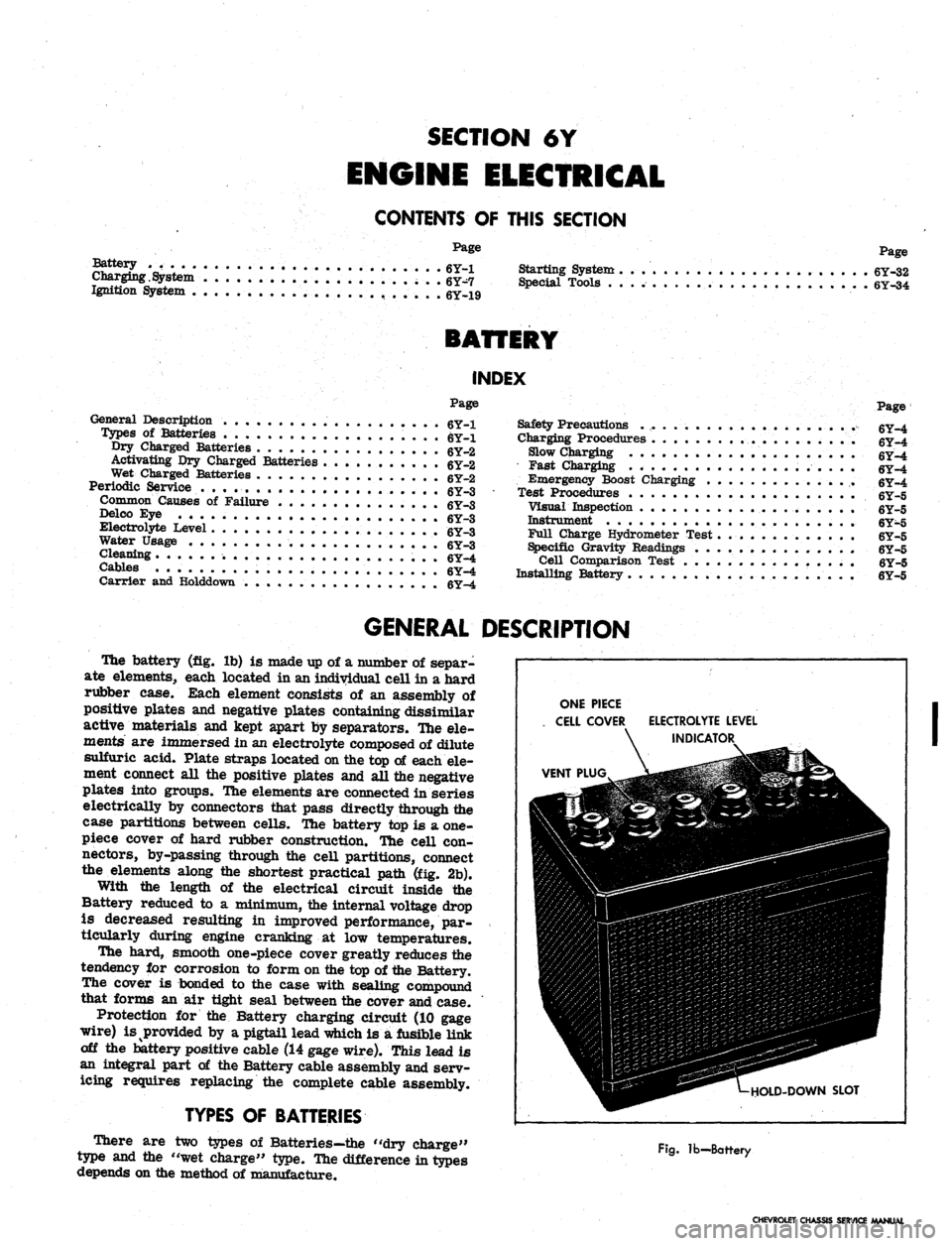
The battery (fig. lb) is made up of a number of separ-
ate elements, each located in an individual cell in a hard
rubber case. Each element consists of an assembly of
positive plates and negative plates containing dissimilar
active materials and kept apart by separators. Hie ele-
ments are immersed in an electrolyte composed of dilute
sulfuric acid. Plate straps located on the top of each ele-
ment connect all the positive plates and all the negative
plates into groups. The elements are connected in series
electrically by connectors that pass directly through the
case partitions between cells. The battery top is a one-
piece cover of hard rubber construction. Tfte cell con-
nectors, by-passing through the cell partitions, connect
the elements along the shortest practical path (fig. 2b).
With the length of the electrical circuit inside the
Battery reduced to a minimum, the internal voltage drop
is decreased resulting in improved performance, par-
ticularly during engine cranking at low temperatures.
The hard, smooth one-piece cover greatly reduces the
tendency for corrosion to form on the top of the Battery.
The cover is bonded to the case with sealing compound
that forms an air tight seal between the cover and case.
Protection for the Battery charging circuit (10 gage
wire) is provided by a pigtail lead which is a fusible Hnk
off the battery positive cable (14 gage wire). This lead is
an integral part of the Battery cable assembly and serv-
icing requires replacing the complete cable assembly.
TYPES
OF
BATTERIES
There are two types of Batteries—the "dry charge"
type and the "wet charge" type. The difference in types
depends on the method of manufacture.
ONE PIECE
CELL COVER
VENT PLUG
ELECTROLYTE LEVEL
INDICATOR
HOLD-DOWN SLOT
Fig.
lb—Battery
CHEVROLET CHASSIS SERVICE MANUAL