1953 JEEP DJ brake
[x] Cancel search: brakePage 34 of 376

TUNE-UP
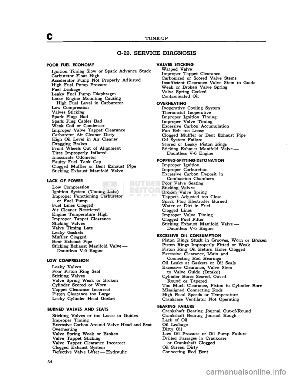
C-29.
SERVICE
DIAGNOSIS
POOR
FUEL ECONOMY Ignition Timing Slow or Spark Advance Stuck
Carburetor
Float High
Accelerator Pump Not Properly Adjusted High Fuel Pump Pressure
Fuel
Leakage
Leaky
Fuel Pump Diaphragm Loose Engine Mounting Causing High Fuel Level in Carburetor
Low
Compression
Valves Sticking
Spark
Plugs Bad
Spark
Plug Cables Bad
Weak
Coil
or Condenser Improper Valve Tappet Clearance
Carburetor
Air Cleaner Dirty
High Oil Level in Air Cleaner Dragging Brakes
Front
Wheels Out of Alignment
Tires
Improperly Inflated Inaccurate Odometer
Faulty
Fuel Tank Cap
Clogged
Muffler or Bent Exhaust Pipe Sticking Exhaust Manifold Valve
LACK
OF POWER
Low
Compression Ignition System (Timing Late)
Improper Functioning Carburetor
or Fuel Pump
Fuel
Lines
Clogged
Air
Cleaner Restricted Engine Temperature High Improper Tappet Clearance
Sticking Valves
Valve Timing Late
Leaky
Gaskets
Muffler
Clogged
Bent Exhaust Pipe Sticking Exhaust Manifold Valve —
Dauntless V-6 Engine
LOW
COMPRESSION
Leaky
Valves Poor Piston Ring Seal Sticking Valves
Valve Spring Weak or Broken
Cylinder
Scored or Worn
Tappet Clearance Incorrect Piston Clearance too Large
Leaky
Cylinder Head Gasket
BURNED
VALVES AND SEATS Sticking Valves or too Loose in Guides
Improper Timing
Excessive Carbon Around Valve Head and Seat Overheating
Valve Spring Weak or Broken
Valve Tappet Sticking
Valve Tappet Clearance Incorrect
Clogged
Exhaust System
Defective
Valve
Lifter
— Hydraulic
VALVES
STICKING
Warped Valve Improper Tappet Clearance Carbonized or Scored Valve
Stems
Insufficient Clearance Valve Stem to Guide
Weak or Broken Valve Spring Valve Spring Cocked Contaminated Oil
OVERHEATING
Inoperative Cooling System
Theromstat Inoperative Improper Ignition Timing
Improper Valve Timing
Excessive Carbon Accumulation
Fan
Belt too Loose
Clogged
Muffler or Bent Exhaust Pipe
Oil
System Failure Scored or Leaky Piston Rings
Sticking Exhaust Manifold Valve — Dauntless V-6 Engine
POPPING-SPITTING-DETONATION
Improper Ignition Improper Carburetion
Excessive Carbon
Deposit
in
Combustion Chambers
Poor Valve Seating Sticking Valves
Broken Valve Spring Tappets Adjusted too Close
Spark
Plug Electrodes Burned
Water or Dirt in Fuel
Clogged
Lines Improper Valve Timing
Clogged
Fuel Filter Sticking Exhaust Manifold Valve —
Dauntless V-6 Engine
EXCESSIVE
OIL CONSUMPTION Piston Rings Stuck in Grooves, Worn or Broken Piston Rings Improperly Fitted or Weak Piston Ring Oil Return
Holes
Clogged
Excessive Clearance, Main and
Connecting Rod Bearings
Oil
Leaks at Gaskets or Oil Seals
Excessive Clearance, Valve Stem
to Valve Guide (Intake)
Cylinder
Bores Scored, Out-of-
Round or Tapered
Too Much Clearance, Piston to Cylinder Bore
Misaligned Connecting Rods
High Road
Speeds
or Temperature
Crankcase
Ventilator Not Operating
BEARING
FAILURE
Crankshaft
Bearing Journal Out-of-Round
Crankshaft
Bearing Journal Rough
Lack
of Oil
Oil
Leakage
Dirty
Oil
Low
Oil Pressure or Oil Pump Failure
Drilled
Passages
in Crankcase or Crankshaft
Clogged
Oil
Screen Dirty
Connecting Rod Bent 34
Page 70 of 376

D
HURRICANE
F4
ENGINE
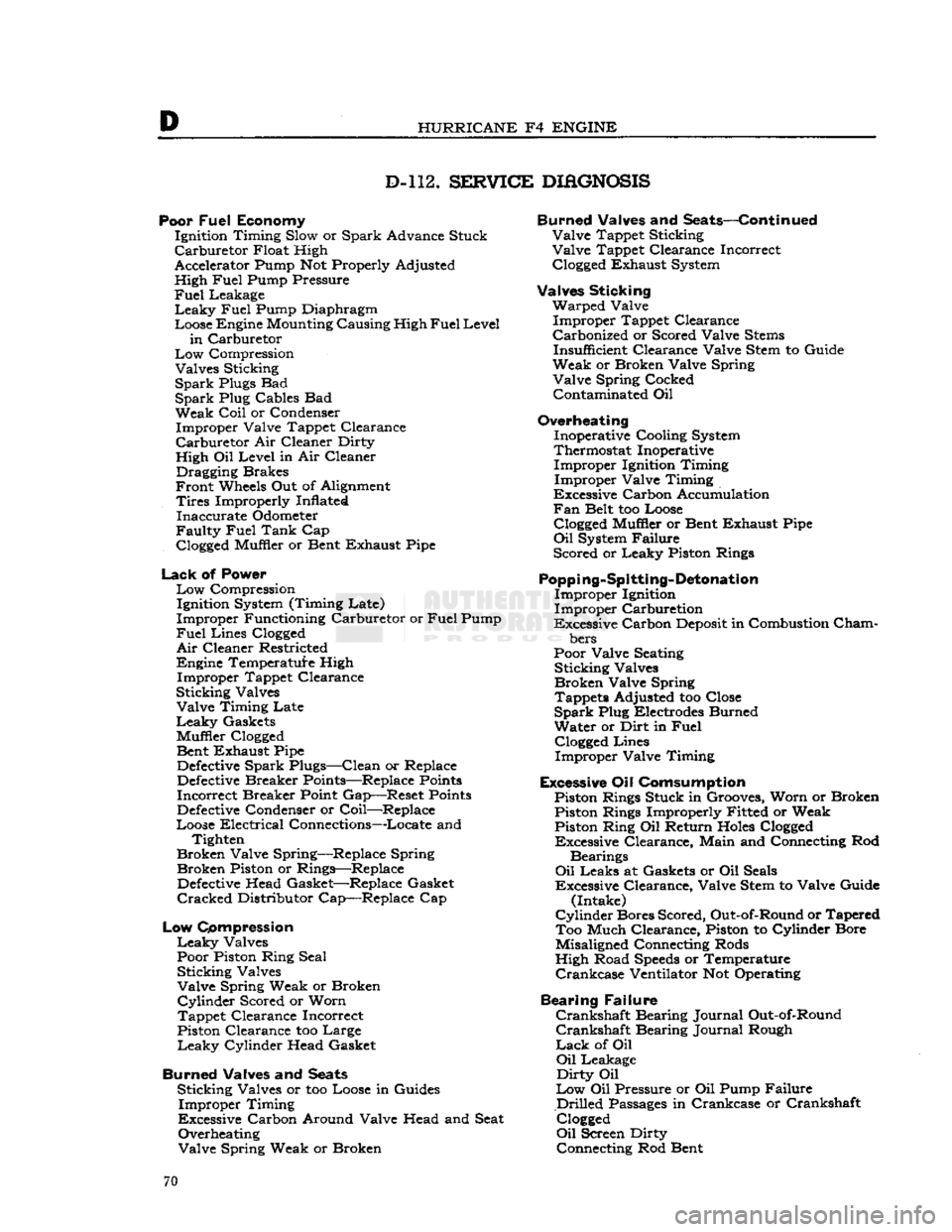
D-112.
SERVICE
DIAGNOSIS
Poor
Fuel
Economy Ignition Timing Slow or Spark Advance Stuck
Carburetor
Float High
Accelerator Pump Not Properly Adjusted
High
Fuel
Pump Pressure
Fuel
Leakage
Leaky
Fuel
Pump Diaphragm
Loose Engine Mounting Causing High
Fuel
Level
in
Carburetor
Low
Compression Valves Sticking
Spark
Plugs Bad
Spark
Plug Cables Bad Weak
Coil
or Condenser Improper Valve Tappet Clearance
Carburetor
Air Cleaner Dirty
High Oil Level in Air Cleaner Dragging Brakes
Front
Wheels Out of Alignment
Tires
Improperly Inflated Inaccurate Odometer
Faulty
Fuel
Tank
Cap
Clogged
Muffler or Bent Exhaust Pipe
Lack
of Power
Low
Compression Ignition System (Timing Late)
Improper Functioning Carburetor or
Fuel
Pump
Fuel
Lines
Clogged
Air
Cleaner Restricted
Engine Temperature High Improper Tappet Clearance
Sticking Valves Valve Timing Late
Leaky
Gaskets
Muffler
Clogged
Bent Exhaust Pipe
Defective
Spark Plugs—Clean or Replace
Defective
Breaker Points—Replace
Points
Incorrect Breaker Point Gap—Reset
Points
Defective
Condenser or Coil—Replace
Loose Electrical Connections—Locate and Tighten
Broken Valve Spring—Replace Spring Broken Piston or Rings—Replace
Defective
Head Gasket—Replace Gasket
Cracked
Distributor Cap—Replace Cap
Low
Compression
Leaky
Valves
Poor Piston Ring Seal Sticking Valves
Valve Spring Weak or Broken
Cylinder
Scored or Worn
Tappet Clearance Incorrect
Piston Clearance too Large
Leaky
Cylinder Head Gasket
Burned Valves and
Seats
Sticking Valves or too Loose in Guides Improper Timing
Excessive Carbon Around Valve Head and Seat Overheating
Valve Spring Weak or Broken Burned Valves and Seats—Continued
Valve Tappet Sticking
Valve Tappet Clearance Incorrect
Clogged
Exhaust System
Valves Sticking Warped Valve Improper Tappet Clearance
Carbonized or Scored Valve
Stems
Insufficient Clearance Valve Stem to Guide
Weak or Broken Valve Spring Valve Spring Cocked Contaminated Oil
Overheating Inoperative Cooling System
Thermostat Inoperative Improper Ignition Timing
Improper Valve Timing
Excessive Carbon Accumulation
Fan
Belt too Loose
Clogged
Muffler or Bent Exhaust Pipe
Oil
System Failure
Scored or Leaky Piston Rings
Popping-Spitting-Detonation
Improper Ignition
Improper Carburetion
Excessive Carbon
Deposit
in Combustion
Cham
bers
Poor Valve Seating Sticking Valves
Broken Valve Spring Tappets Adjusted too Close
Spark
Plug Electrodes Burned
Water or Dirt in
Fuel
Clogged
Lines Improper Valve Timing
Excessive Oil Comsumption Piston Rings Stuck in Grooves, Worn or Broken Piston Rings Improperly Fitted or Weak Piston Ring Oil Return
Holes
Clogged
Excessive Clearance, Main and Connecting Rod
Bearings
Oil
Leaks at Gaskets or Oil Seals
Excessive Clearance, Valve Stem to Valve Guide (Intake)
Cylinder
Bores Scored, Out-of-Round or Tapered Too Much Clearance, Piston to Cylinder Bore
Misaligned Connecting Rods
High Road
Speeds
or Temperature
Crankcase
Ventilator Not Operating
Bearing Failure
Crankshaft
Bearing Journal Out-of-Round
Crankshaft
Bearing Journal Rough
Lack
of Oil
Oil
Leakage
Dirty
Oil
Low
Oil Pressure or Oil Pump Failure
Drilled
Passages
in Crankcase or Crankshaft
Clogged
Oil
Screen Dirty Connecting Rod Bent 70
Page 71 of 376

'Jeep*
UNIVERSAL
SERIES
SERVICE
MANUAL
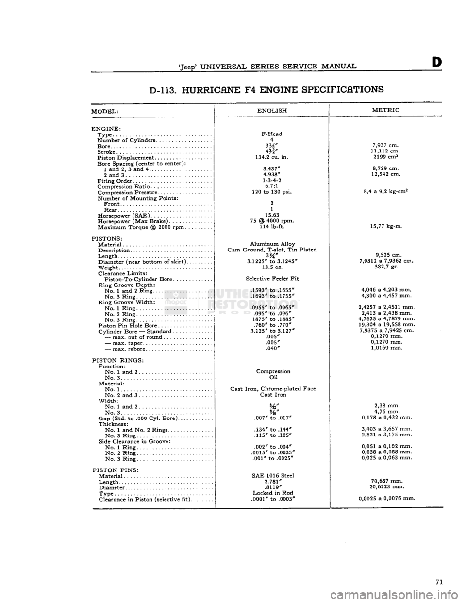
D D-l 13. HURRICANE
F4
ENGINE SPECIFICATIONS
MODEL:
ENGLISH
ENGINE:
Type
Number of Cylinders
Bore
Stroke
Piston Displacement...........
Bore
Spacing (center to center): 1 and 2, 3 and 4
2 and 3
Firing
Order Compression Ratio Compression Pressure... .
Number of Mounting Points:
Front
Rear
Horsepower (SAE)
Horsepower (Max Brake) Maximum Torque @
2000
rpm.
PISTONS:
Material
Description
Length
,.
Diameter (near
bottom
of
skirt).
Weight.
Clearance
Limits:
Piston-To-Cylindcr
Bore
Ring
Groove Depth:
No. 1 and 2 Ring No. 3 Ring
Ring
Groove Width:
No. 1 Ring No. 2 Ring
No. 3 Ring
Piston Pin Hole Bore
Cylinder
Bore — Standard.....
—
max. out of round
F-Head
4
W
134.2 cu. in.
3.437"
4.938"
1-3-4-2
6.7:1
120 to 130 psi.
2
1
15.63
@
4000
rpm. 114 lb-ft. 75
-
max. taper..
-
max. rebore.
PISTON RINGS:
Function:
No. 1 and 2 No. 3. .
Material:
No. 1. .
No. 2 and 3
Width;
No. 1 and 2
No. 3. . . .
Gap
(Std. to .009 Cyl. Bore).
Thickness:
No. 1 and No. 2 Rings....
No. 3 Ring
Side Clearance in Groove:
No. 1 Ring No. 2 Ring
No. 3 Ring
PISTON
PINS:
Material
Length
Diameter
Type
Clearance
in Piston
(selective
fit).
Aluminum
Alloy
Gam
Ground, T-slot, Tin Plated
3.1225*
to
3.1245*
13.5 oz.
Selective Feeler Fit
.1593" to .1655"
.1693" to .1755"
.0955" to .0965" .095" to .096"
1875" to .1885" .760" to .770"
3.125"
to
3.127"
.005" .005" .040"
Compression
Oil
Cast
Iron,
Chrome-plated Face
Cast
Iron
.007" to .017"
.134" to .144" .115" to .125"
.002" to .004"
.0015" to .0035" .001" to .0025"
SAE
1016 Steel
2.781"
.8119"
Locked
in Rod
.0001"
to .0003"
METRIC
7,937
cm.
11,112
cm. 2199 cm*
8,729
cm.
12,542
cm.
8,4 a 9,2 kg-cm2
15,77 kg-m.
9,525
cm.
7,9311
a
7,9362
cm.
382,7
gr.
4,046
a
4,203
mm.
4,300
a
4,457
mm.
2,4257
a
2,4511
mm. 2,413 a
2,438
mm.
4,7625
a
4,7879
mm.
19,304
a
19,558
mm.
7,9375
a
7,9425
cm.
0,1270
mm.
0,1270
mm.
1,0160
mm.
2,38 mm.
4,76 mm.
0,178 a
0,432
mm.
3,403
a
3,657
mm. 2,821 a 3,175 mm.
0,051 a 0,102 mm.
0,038
a
0,088
mm.
0,025
a
0,063
mm.
70,637
mm.
20,6223
mm.
0,0025
a
0,0076
mm. 71
Page 105 of 376

'Jeep'
UNIVERSAL
SERIES SERVICE
MANUAL
Dl
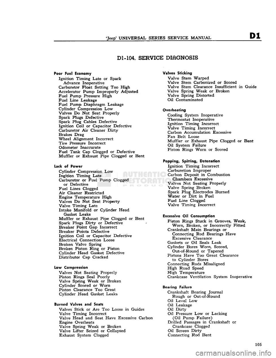
Dl-104.
SERVICE
DIAGNOSIS
Poor Fuel Economy
Ignition Timing Late or Spark Advance Inoperative
Carburetor
Float Setting Too High
Accelerator Pump Improperly Adjusted
Fuel
Pump Pressure High
Fuel
Line
Leakage
Fuel
Pump Diaphragm Leakage
Cylinder
Compression Low
Valves Do Not Seat Properly
Spark
Plugs
Defective
Spark
Plug Cables
Defective
Ignition
Coil
or Capacitor
Defective
Carburetor
Air Cleaner Dirty
Brakes
Drag
Wheel Alignment Incorrect
Tire
Pressure Incorrect Odometer Inaccurate
Fuel
Tank
Cap Clogged or
Defective
Muffler or Exhaust Pipe Clogged or Bent
Lack
of
Power
Cylinder
Compression Low
Ingitdon Timing Late
Carburetor
or
Fuel
Pump Clogged or
Defective
Fuel
Lines Clogged
Air
Cleaner Restricted
Engine Temperature High Valves Do Not Seat Property
Valve
Timing Late Intake Manifold or Cylinder Head
Gasket Leaks
Muffler or Exhaust Pipe Clogged or Bent
Spark
Plugs Dirty or
Defective
Breaker
Point Gap Incorrect
Breaker
Points
Defective
Ignition
Coil
or Capacitor
Defective
Electrical
Connection Loose
Broken
Valve Spring
Broken
Piston Ring or Piston
Cylinder
Head Gasket
Defective
Distributor Cap Cracked
Low
Compression
Valves Not Seating Properly Piston Rings Seal Poorly
Valve
Spring Weak or Broken
Cylinder
Scored or Worn
Piston Clearance Too Great
Cylinder
Head Gasket Leaks
Burned
Valves and
Seats
Valves Stick or Are Too Loose in Guides
Valve
Timing Incorrect
Valve
Head and Seat Have Excessive Carbon
Engine Overheats
Valve
Spring Weak or Broken
Valve
Lifter Seized or Collapsed
Exhaust
System Clogged
Valves Sticking
Valve
Stem Warped
Valve
Stem Carbonized or Scored
Valve
Stem Clearance Insufficient in Guide
Valve
Spring Weak or Broken
Valve
Spring Distorted
Oil
Contaminated
Overheating
Cooling System Inoperative
Thermostat Inoperative Ignition Timing Incorrect
Valve
Timing Incorrect
Carbon
Accumulation Excessive
Fan
Belt Loose
Muffler or Exhaust Pipe Clogged or Bent
Oil
System Failure
Piston Rings Worn or Scored
Popping,
Spitting,
Detonation
Ignition Timing Incorrect
Carburetion
Improper
Carbon
Deposit
in Combustion
Chambers Excessive
Valves Not Seating Properly
Valve
Spring Broken
Spark
Plug Electrodes Burned
Water or Dirt in
Fuel
Fuel
Line
Clogged
Valve
Timing Incorrect
Excessive
Oil
Consumption
Piston Rings Stuck in Grooves, Weak,
Worn,
Broken, or Incorrectly Fitted
Crankshaft
Main Bearings or
Connecting Rod Bearings Have
Excessive Clearance
Gaskets or Oil Seals
Leak
Cylinder
Bores Worn, Scored,
Out-of-Round or Tapered
Pistons Have Too Great Clearance to Cylinder Bores
Connecting Rods Misaligned High Road Speed
High Temperature
Crankcase
Ventilation System Inoperative
Bearing Failure
Crankshaft
Bearing Journal Rough or Out-of-Round
Oil
Level Low
Oil
Leakage
Oil
Dirty
Oil
Pressure Low or Lacking
(Oil
Pump Failure)
Drilled
Passages
in Crankshaft or
Crankcase
Clogged
Oil
Screen Dirty
Connecting Rod Bent 105
Page 106 of 376

Dl
DAUNTLESS
V-6
ENGINE
E-105.
DAUNTLESS V-6 ENGINE SPECIFICATIONS
ENGINE:
Type
Number
of Cylinders Valve Arrangement
Bore
Stroke
Piston
Displacement
Firing
Order Compression Ratio
Number
of
Mounting
Points:
Front.
Horsepower
(SAE)
Horsepower
(max. brake) Torque (max.
2400
rpm.)
Cylinder
Numbers,
Front to Rear:
Right Bank
Left
Bank
Cylinder Block Material
Cylinder Head Material English
90°
V-6 6
In
head
3.750"
3.400"
225 cu. in.
1.6.5.4.3.2
*9.0:1
2
33.748
160 @
4200
rpm. 235
lb-ft.
2, 4, 6 1, 3, 5
Cast
Iron
Cast
Iron Metric
9,525
cm.
8,636
cm. 3,69 ltr.
32,49
kg-m.
PISTONS:
Material
Description Clearance Limits:
Top
Land
Skirt
Top
Skirt
Bottom
Ring Groove Depth*. No. 1
No. 2, 3
Cylinder Bore: Out-of-Round (max.). Taper (max.)
Cast
Aluminum Alloy
Cam
Ground, Tin Plated
.0125"
to
.0295" .0005"
to
.0011"
.0005"
to
.0011"
.1880"
to
.1995"
.1905"
to
.1980"
.003"
.005" 0,318 a
0,749
mm.
0,0127
a
0,0279
mm.
0,0127
a
0,0279
mm.
4,775
a
5,067
mm.
4,839
a
5,029
mm.
0,076
mm. 0,127 mm.
PISTON
RINGS:
Function: No. 1 and No. 2 Ring.. No. 3 Ring
Location
Material: No. 1...
No. 2 No. 3.
Oil
Ring Type
Oil
Ring Expander
Width: No. 1
No. 2. .
No. 3
Gap:
No. 1 and No. 2
No. 3
Side
Clearance in Groove: No. 1
No. 2
No. 3 Compression
Oil
Control
Above
Piston
Pin
Iron,
Chrome Plated
Iron,
Pre lubricated
Steel
Dual
Rail,
With Spacer Humped Ring
.0785"
to
.0790" .0770"
to
.0780"
.181" to .187"
.010" to .020"
.015" to .035"
.002" to
.0035"
.003" to .005"
.0015"
to
.0085"
1,993 a
2,007
mm.
1,956 a 1,981 mm. 4,60 a 4,75 mm.
0,25 a 0,51 mm.
0,38 a 0,89 mm.
0,051 a
0,089
mm.
0,076
a 0,127 mm.
0,038
a
0,220
mm.
PISTON
PINS:
Material
Length
Diameter
Type Clearance in
Piston
Clearance in
Connecting
Rod.
Distance
Offset
Toward High-Thrust
Side
of Piston.
Steel,
SAE 1018, SAE 1118
3.060"
.9394"
to
.9397"
Pressed in
Connecting
Rod
.0004"
to
.0007" .0007"
to
.0017"
.040"
7,772
cm.
23,861
a
23,868
mm.
0,0102
a
0,0178
mm.
0,0178
a
0,0431
mm.
1,016 mm.
*State
of California Exhaust Emission Control Engine 7.4 Compression Ratio.
106
Page 134 of 376

E
FUEL
SYSTEM
E-78. SERVICE DIHGNOSIS
Symptoms Probable Remedy
Excessive
Fuel
Consumption:
Tires
improperly inflated Inflate
Brakes
drag Adjust
Engine
operates too cold Check thermostat
Heat control valve inoperative Check thermostatic spring
Leak
in fuel line Check all connections
Carburetor
float level high. See
"Carburetor"
section
Accelerator pump not properly adjusted Adjust
Leaky
fuel pump diaphragm Replace
Loose
engine
mountings causing high carburetor fuel level Tighten Ignition timing slow or spark advance stuck See "Distributor" section
Low
compression. Check valve tappet clearance
Air
cleaner dirty
.
Remove and clean
Engine
Hesitates on Acceleration: Accelerator pump
does
not function perfectly.
...................
.Replace piston and rod or adjust
Carburetor
float level. ... .Adjust
Spark
plugs Replace or clean and adjust
Low
compression Check valves
Distributor
points—dirty or pitted Replace
Weak
condenser or coil Replace
Carburetor
jets restricted Remove and clean
Excessive
engine
heat See "Engine" section
Engine
Stalls—Won't Idle:
Improper
condition of carburetor See
"Carburetor"
section
Low
speed
jet restricted Remove and clean
Dirty
fuel sediment bowl screen Remove and clean
Air
cleaner dirty Remove and clean
Leaky
manifold or gasket Replace
Fuel
pump diaphragm porous. Replace
Loose carburetor. Tighten
flange
nuts
Water
in fuel
Drain
and clean system
Improper
ignition. .See "Distributor" section
Spark
plugs Clean and adjust
Valves
sticking.
Grind
valves 134
Page 213 of 376

'Jeep'
UNIVERSAL
SERIES SERVICE
MANUAL
H
FIG.
H-52—MAIN
LIGHT SWITCH (LATE)
1—
Circuit
Breaker
2—
Light
Switch
3—
Rear
Lights
4—
Head
Lights
5—
Parking
Lights
The
light switch shown in
Fig.
H-51 was superseded
by the one shown in
Fig.
H-52.
H-127.
Headlight Dimmer Switch To
remove the headlight dimmer switch, first raise
the hood and disconnect the wires attached to the
switch.
Then
remove the two screws that hold the
dimmer
switch to the floor board. Remove the
switch.
Check
the operation of the dimmer switch
with
a
test
light. A
circuit
across two different pairs of contacts (one to headlights, the other to the
high-beam indicator light) should alternately light
the
test
lamp when the switch is operated.
H-128.
Stop Light Switch
The
stop
light switch is of the diaphragm type.
Should
the switch
become
inoperative, it is neces
sary
to install a new one.
Current
production vehicles are equipped with two
stop
light switches
that operate independently of each other. Both
switches are located along the
left
side of frame, in the front and
rear
brake lines.
Caution:
Do not apply the brakes while making
this exchange as air may enter the hydraulic line.
Bleed
the brakes after replacing the switch.
Fig.
H-54 shows the wiring of the
stop
light
circuit.
11500
FIG.
H-53—STOP
LIGHT SWITCH
FIG.
H-54—STOP
LIGHT CIRCUIT
1— Stop
Light
Switch
2—
Light
Switch
3—
Tail
Light
H-129. Head Lamp Service
H-130.
Head Lamp Replacement
Refer
to Fig. H-59.
Each
sealed beam head lamp can only be replaced as a
complete
unit.
A
sealed beam unit may be replaced by the fol lowing procedure:
a.
Remove door screw.
b.
Remove door.
c.
Remove retaining screws and retaining
ring.
d.
Remove sealed beam unit.
Installation
of sealed beam unit is the reverse of
above procedure. When replacing head lamps,
check
lamp aim following procedures described in
Par.
H-132.
FIG.
H-55—PARKING
LIGHT (EARLY)
1—
Bezel
2—
Lens
3—
Bulb
4—
Gasket
5—
Housing
and Cable
6—
Screw
213
Page 224 of 376

H
ELECTRICAL
SYSTEM
H-152.
ELECTRICAL
SPECIFICATIONS—Continued
HURRICANE DAUNTLESS
V-6
DAUNTLESS
V-6 ENGINE
MODEL -
F4
ENGINE
ENGINE
LATE
MODELS
EARLY
MODELS
IGNITION
COIL
BALLAST
]Make Delco-Remy
Prestolite Prestolite
Model
None
1957154
PU
5003
PU
5003
Ohms • • 1.80 @
80°F.
.495 - .605 @
75°F.
.495 - .605 @
75°F.
1.80 @
80°F.
.638 - .835 @
212°F.
.638 - .835 @
212°F.
DISTRIBUTOR:
Prestolite Delco-Remy Prestolite Prestolite
Model
•
(a)
LAY
4012, 4401
1110376
I
AT
4501 or
IAT
4502A
(b)
I
AY
4401A, 44011
IAT
4502
Breaker
Point Gap (b)
.020"
[0,508
mm.] .016"
[0,406
mm.] .016"
[0,406
mm.]
.016"
[0,406
mm.]
Breaker
Arm Tension. ..... 17 to 20 oz.
19 to 23 oz. 17 to 22 oz. 17 to 22 oz.
[482 a 567 gr.] [538 a 652 gr.] [482 a 624 gr.]
[482 a 624 gr.]
42° 29°
to 31°
29°
±3°
29°
±3°
Max.
Auto Advance
(Crankshaft
Degrees) •(a)
11°
@ 1,700 rpm.
13°
to
15°
at 1,950 rpm.
16°
@ 1,800 rpm.
21°
(2 1,800 rpm.
(Crankshaft
Degrees)
(b)
13.5°
@ 1,700 rpm.
26°
@
4200
rpm.
32°
@
4200
rpm.
Max.
Vac. Advance go
(Distributor Degrees)., . .
None
8° 8°
go
Condenser Capacity. . .25 to .28 mfd. .18 to .23 mfd. .25 to .28 mfd. .25 to .28 mfd.
TIMING:
Crankshaft
See
Note
See
Note
See
Note
See
Note
Mark
Location............
Crankshaft
Pulley
Crankshaft
Pulley
Crankshaft
Pulley
Csankshaft
Pulley
Firing
Order
1-3-4-2
1-6-5-4-3-2
1-6-5-4-3-2 1-6-5-4-3-2
SPARK PLUGS:
Make
Champion
A.C. A.C.
or Champion
A.C.
or Champion
J8
44S
44S or UJ 12Y 44S or UJ 12Y
Thread
14 mm.
14 mm. 14 mm. 14 mm.
Thread
Reach
Vz"
[9,47 mm.]
%"
[9,47 mm.]
¥%"
[9,47 mm.]
V8" [9,47 mm.]
Gap
.030"
[0,762
mm.]
.035"
[0,900
mm.] .035"
[0,900
mm.] .035"
[0,900
mm.|
LAMP BULB TRADE
NUMBERS:
Headlight 6012
6012 6012 6012
Parking
and Directional Signals. 1157NA
1157NA 1157NA 1157NA
License
Plate Light........ 1155
1155 1155 1155
Marker
and Reflector 194
194 194 194
INDICATOR LIGHTS:
57 57 57 57
Directional Signals........ 57
57 57 57
Charge
57
57 57 57
57 57 57 57
1156 1156 1156 1156
Instrument Cluster 57 57 57 57
Warning
— 4 Way Flasher. . 57
57 57 57
Brake
Warning Light 57
57 57 57
FUSE
DATA:
Heater 9 amp. 9 amp. 9 amp. 9 amp.
Backup
14 amp. 14 amp. 14 amp. 14 amp.
WS/Wiper.
14 amp. 14 amp. 14 amp. 14 amp.
Directional Signal 9 amp. 9 amp. 9 amp. 9 amp.
4-Way Flasher 14 amp. 14 amp. 14 amp. 14 amp.
Brake
Warning Light 9 amp. 9 amp. 9 map. 9 amp.
FLASHER
DATA:
Directional Signals. 144
144 144 144
Hazzard
Warning. 170
170 170 170
NOTE:
0°
T.D.C.
on Distributor
models
IAY 4401A, IAY 4401B, IAT 4502A.
NOTE:
5°
B.T.C.
on Distributor
models
IAY 4012, IAY 4401, IAT 4501, IAT 4502,
1110376.
224