1953 JEEP CJ Wheel bearing
[x] Cancel search: Wheel bearingPage 229 of 376
'Jeep'
UNIVERSAL
SERIES SERVICE
MANUAL
I
Note:
The clutch release bearing is lubricated at
time of assembly and no attempt should be made
to lubricate it Refer to Fig. 1-23 when lubricating
the clutch throwout bearing collar. c. Reassembly
To
assemble the clutch to the flywheel, first put
a
small amount of light cup grease in the flywheel
pilot bushing, install the driven plate, with short
end of hub toward the flywheel, then place the pressure plate assembly in position.
With
a clutch
plate aligning arbor or a spare transmission main
shaft, align the driven plate splines leaving the
arbor
in position while tightening the pressure plate
screws evenly.
Next, assemble the flywheel housing to the
engine
and
reinstall the transmission and transfer case or
install
the
engine
in the vehicle, depending on the
procedure of removal. Make sure that the clutch
release bearing
carrier
return spring is hooked in place. For the remainder of the assembly reverse
the operations that were used in removing the
transmission and transfer case or the
engine
referring
to the instructions given in Section J for the transmission and Section D and Dl for the
engine.
d.
Adjust the clutch control cable so there is 3A" [19,05 mm.] free pedal travel. (Refer to Par. 1-3)
1-10.
CLUTCH
—
DAUNTLESS
V-6
ENGINE
•
Diaphragm Spring Type
(Early
Models)
*
Jeep' vehicles equipped with a Dauntless V-6 en
gine
use a 10.4" [26,4 cm.] single-plate, dry-disc
clutch,
incorporating a diaphragm-type spring as
sembly.
When
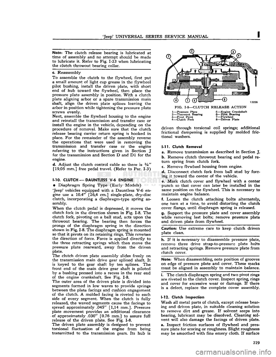
the clutch pedal is depressed, it
moves
the
clutch
fork in the direction shown in Fig. 1-8. The
clutch
fork, pivoting on a
ball
stud, acts upon the
throwout bearing. The bearing then forces the
prongs of the diaphragm spring in the direction shown in
Fig.
1-8. The diaphragm spring is mounted
so that it pivots on its retaining rings.
This
reverses
the direction of force.
Force
is applied directly to
the three retracting springs which then
move
the
pressure plate
rearward,
away from the driven plate.
The
clutch driven plate assembly slides freely on
the transmission main drive gear splined shaft. It is keyed to the gear shaft by ten splines. The
front end of the main drive gear shaft is piloted by a bushing pressed into a recess in the
rear
end
of the
engine
crankshaft. See Fig. 1-8.
The
outer area of the driven plate is divided into
segments
formed in low waves to provide springs
between
the plate facings and cushion
engagement
of the clutch. A molded facing is riveted to each
side of every
segment.
When the clutch is fully
released, the waved
segments
cause the facings to
spread
approximately .045" [1,14 mm.]. Pressure
plate movement provides an additional clearance
of approximately .030" [0.76 mm.] to assure
full
release of the driven plate. See Fig. 1-8.
The
driven plate assembly is designed to prevent
torsional fluctuation of the
engine
from being
transmitted to the transmission gears. Its hub is
FIG.
1-8—CLUTCH
RELEASE
ACTION
1—
Pressure
Plate 5—Engine
Crankshaft
2—
Throwout
Bearing
6—Pilot
Bearing
3—
Pivot
Point
7—Flywheel
4—
Clutch
Fork
8—Driven
Plate
driven
through torsional coil springs; additional
frictional
dampening is supplied by molded
fric-
tional washers.
1-11.
Clutch
Removal
a.
Remove transmission as described in Section J. b. Remove clutch throwout bearing and pedal re
turn
spring from clutch fork.
c. Remove flvwheel housing from engine.
d.
Disconnect clutch fork from
ball
stud by forc
ing it toward the center of the vehicle.
e.
Mark
clutch cover and flywheel with a center
punch
so that cover can later be installed in the same position on the flywheel.
This
is necessary to
maintain
engine
balance.
f. Loosen the clutch attaching
bolts
alternately,
one
turn
at a time, to avoid distorting the clutch
cover flange, until diaphragm spring is released.
g. Support the pressure plate and cover assembly
while removing last bolts; remove pressure plate
and
driven plate from flywheel.
Caution:
Use extreme care to keep clutch driven plate clean.
h.
If it is necessary to disassemble pressure plate,
remove three drive strap-to-pressure plate
bolts
and
retracting springs. Remove pressure plate from
clutch
cover.
Note:
When disassembling,
note
position of
grooves
on
edge
of pressure plate and cover. These marks must be aligned in assembly to maintain balance.
i.
The clutch diaphragm spring and two pivot rings
are
riveted to the clutch cover. Inspect spring, rings
and
cover for excessive wear or damage. If there
is a
defect,
replace the complete cover assembly.
1-12.
Clutch
inspection
Wash
all metal parts of clutch, except release bear
ing and driven plate, in suitable cleaning solution to remove
dirt
and grease. If solvent
seeps
into
bearing,
lubricant may be dissolved. Cleaning sol
vent
will
also damage the facings of driven plate,
a.
Inspect friction surfaces of flywheel and pres
sure
plate for scoring or roughness. Slight roughness
may be smoothed with fine emery cloth. If surface 229
Page 230 of 376

CLUTCH
is deeply scored or grooved, the part should be
replaced.
b. Inspect driven plate for wear or damage to fac
ings,
loose
rivets, broken or
loose
torsion springs,
and
flattened cushion springs. If facings are worn
near
rivets or are oily, replace the plate assembly.
A
slight amount of oil on clutch facings
will
cause
clutch
grab and chatter; excessive oil on facings
will
cause slippage. It is not practical to remove
oil
with solvents or by buffing since oil
will
con
tinue to bleed from facing material when hot. If
oil
is found on driven plate facings, examine trans
mission drainback hole, pilot bushing,
engine
rear
main
bearing and other points of possible oil leakage. Test the fit of driven plate hub on trans
mission main drive gear for an easy sliding fit.
c. Inspect clutch release bearing for scoring or ex cessive wear on front contact face. Test for rough
ness
of balls and races by pressing and turning
front race slowly. Inspect main drive gear pilot
bushing in crankshaft. Replace bushing if it is rough or worn. Regardless of whether the old plate
or
a new plate is to be installed, check the plate
for runout. Slide the driven plate, front side first,
over the transmission main drive gear shaft so that
it
is tight on the spline. Index a
dial
indicator to the plate facing as shown in
Fig.
1-9. While holding
firmly
against front end of main drive gear, to take up play in main drive gear bearing, slowly
rotate driven plate and observe the amount of
run
out shown by indicator. If runout of front facing
exceeds
.025" [0,635 mm.], replace the plate. It
is not practical to correct excessive runout by bending. 12769
FIG.
1-9—RUNOUT
CHECK
—
CLUTCH
PLATE
1—
Front
Facing
(Flywheel
Side)
2—
Dial
Indicator
Set
d.
Check
clutch pilot bushing for excessive wear
or
damage. Replace pilot bushing, if necessary, with
special
removal and installation
tools.
(See
Figs.
1-6 and 1-7). 1-13.
SERVICING
CLUTCH
PRESSURE
PLATE
AND
DISC
—
BORG
&
BECK
V6
(Late
Models)
The
Borg & Beck clutch is a single plate, dry disk
type. It provides smooth
engagement
of
engine
power to the wheels. The clutch consists of a pres
sure
plate assembly with pressure springs and
release levers, and driven plate assembly. The
driven
plate assembly
uses
spring center vibration
neutralizes and two flexible facings.
The
clutch driven plate is spring cushioned with a facing riveted to both sides. The coil springs around
the hub absorb the power shocks and cushion the
driving
mechanism. The clutch throw-out bearing is of the
ball
type, packed at time of manufacture,
and
requires no further lubrication.
No adjustment for wear is provided in the clutch itself. An individual adjustment is built into the
clutch
cover to adjust the height of the release
levers.
This
adjusting nut is locked in position
and
should never be disturbed unless the clutch assembly has been disassembled for the replace
ment of worn parts or to correct the height of the release levers.
When
the clutch pedal is depressed (disengaged),
the release bearing is moved toward the flywheel
and
contacts the inner ends of the release levers.
Each
lever is pivoted on a floating pin which re
mains stationary in the lever and rolls across a short flat portion of the enlarged
hole
in the eye-
bolt. The outer ends of the
eyebolts
extend
through
holes
in the stamped cover and are fitted
with
adjusting nuts to secure the levers in the
correct
position. The outer ends of the release levers
engage
the pressure plate lugs by means of ful-
crums,
which provide knife-edge contact
between
the outer ends of the levers and the lugs as shown
in
Fig.
I-10. 12190
FIG.
MO—CLUTCH
LEVER
POSITIONS
A—Clutch
Engaged
B—Clutch
Disengaged 1-14.
Clutch
Pressure Plate Adjustment
The
clutch pressure plate adjustment must be
checked before installing a new or reconditioned
clutch.
The proper spacer thickness and
gage
length for a particular clutch is listed in Par. 1-30.
Use
Clutch
Adjusting
Fixture
W-296. If the W-296
fixture is not available one can be fabricated as
described in Par. 1-26. 230
Page 233 of 376
'Jeep*
UNIVERSAL SERIES
SERVICE
MANUAL
b.
Check
the anti-rattle springs in the clutch cover
and
place the cover on top of the pressure plate
assembly. The top of each pressure spring must enter its spring seat in the cover.
Line
up punch
marks
on cover and pressure plate for balance.
c.
Slowly compress the cover making sure that
the
eyebolts
and pressure plate lugs are guided through the proper
holes
in the cover.
d.
Hold the clutch under compression and screw
down the adjusting nuts until they are flush with
the
tops
of the eyebolts. Release the spindle of
the press.
1-24.
Clutch
Lever Adjustment
Important:
Always inspect release lever height
adjustment when installing a new clutch drive
plate.
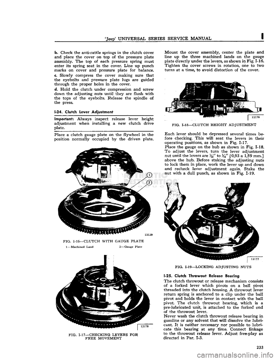
Place
a clutch
gauge
plate on the flywheel in the
position normally occupied by the driven plate.
FIG.
1-16—CLUTCH WITH GAUGE
PLATE
1—Machined
Land
2—Gauge Plate
FIG.
1-17—CHECKING
LEVERS
FOR
FREE
MOVEMENT
Mount
the cover assembly, center the plate and
line up the three machined lands on the
gauge
plate directly under the levers, as shown in
Fig.
1-16.
Tighten
the cover screws in rotation, one to two
turns
at a time, to avoid distortion of the cover.
FIG.
1-18—CLUTCH HEIGHT ADJUSTMENT
Each
lever should be depressed several times be
fore checking.
This
will
seat the levers in their operating positions, as shown in Fig. 1-17.
Place
the
gauge
on the hub as shown in Fig. 1-18.
To
adjust the levers,
turn
the lever adjustment nut until the levers are
%{'
to %6" [0,93 a 1,59 mm.]
above the hub. Before staking the adjusting nuts
to lock them in place, work the lever up and down
and
recheck lever adjustment again. Stake the nut with a
dull
punch, as shown in Fig. 1-19.
FIG.
1-19—LOCKING ADJUSTING NUTS
1-25.
Clutch Throwout
Release Bearing
The
clutch throwout or release mechanism consists
of a forked lever which pivots on a
ball
pivot threaded into the clutch housing. A throwout lever
return
spring is anchored to a clip under the
ball
pivot and holds the lever in contact with the
ball
pivot. The clutch throwout bearing, which is a
pre-lubricated
unit, is attached to the forked end of the throwout lever.
Never wash the clutch throwout release bearing in
gasoline or any solvent that
will
dissolve the
lubri
cant.
It is neither necessary nor possible to
lubri
cate this bearing at any time. Connect linkage
to the throwout release lever. Adjust free-play as
directed
in Par. 1-3. 233
Page 235 of 376
![JEEP CJ 1953 Service Manual
Jeep
UNIVERSAL
SERIES
SERVICE
MANUAL
I thickness: .285"
[0,724
cm.], .305"
[0,775
cm.].
Each
spacer should be hardened and ground to size, and then have the dimensional thickness
sta](/manual-img/16/57040/w960_57040-234.png "JEEP CJ 1953 Service Manual
Jeep
UNIVERSAL
SERIES
SERVICE
MANUAL
I thickness: .285\"
[0,724
cm.], .305\"
[0,775
cm.].
Each
spacer should be hardened and ground to size, and then have the dimensional thickness
sta")
'Jeep'
UNIVERSAL
SERIES
SERVICE
MANUAL
I thickness: .285"
[0,724
cm.], .305"
[0,775
cm.].
Each
spacer should be hardened and ground to size, and then have the dimensional thickness
stamped thereon.
c.
From
flat bar stock at least Vfe" [3 mm.] thick,
make a
gauge
as shown in Fig. 1-22. Harden, grind
to size, and stamp sizes on the
gauge.
1-27.
Clutch Installation
a.
Very
sparingly, apply wheel bearing lubricant
to inner surface of pilot bushing in crankshaft.
Caution:
If
excessive
lubricant is applied to pilot bushing, it
will
run out on face of flywheel when
hot and
ruin
the driven plate facings.
b. Make sure that splines in the driven plate hub
are
clean; apply a light coat of lubricant to splines
of hub and transmission drive gear shaft. Slide plate over gear shaft several times; remove plate
from shaft and wipe off
excess
lubricant.
Caution:
Driven plate facings must be kept clean
and
dry.
c.
Fill
groove
in throwout bearing collar with wheel bearing lubricant. See Fig. 1-23. Make sure
that front bearing retainer of transmission is clean;
apply a light coat of wheel bearing lubricant. Slide
throwout bearing over bearing retainer several times. Remove bearing from retainer and wipe off
excess
lubricant.
12736
FIG.
1-23—LUBRICATION
POINTS
—
CLUTCH
THROWOUT
BEARING
COLLAR
1—Coat
This
Groove 2—Pack
This
Recess
d.
Clean
and apply wheel bearing lubricant to ball
stud in flywheel housing and to the
seat
in clutch
fork.
e.
If disassembled, install pressure plate in the cover assembly, lining up the
groove
on its
edge
with the
groove
on the
edge
of the cover.
Install
pressure plate retracting springs, and the three
drive
strap-to-pressure plate
bolts
and lock washers.
Torque
bolts
11 lb-ft. [1,51 kg-m.].
Note:
The diaphragm
type
clutch assembly is fac
tory calibrated and requires no adjustment
before
installation. Refer to Par. 1-14 to adjust Borg and
Beck
coil spring
type
clutch assembly.
f.
Install
the pressure plate and driven plate on
flywheel. Support both assemblies with a spare
main
drive gear.
Note:
Be certain that
mark
on clutch cover is
aligned with the
mark
made on the flywheel during
clutch removal.
g.
Install
clutch attaching
bolts
and tighten alter nately so that clutch is drawn squarely
into
position
on flywheel.
Each
bolt
must be
tightened
one turn at a time to avoid bending the clutch cover flange.
Torque
bolts
30 to 40 lb-ft. [4,1 a 5,5 kg-m.].
h.
Lubricate
the ball stud and clutch fork with
wheel bearing lubricant and install clutch fork.
Note:
Be certain that fork retaining spring is
tight
on pivot ball stud.
i.
Install
flywheel housing on
engine
cylinder
block.
Caution:
Be certain that dowel pins are installed
in
cylinder block.
j.
Lubricate
the recess on the inside of the throw-
out bearing collar. Be careful not to use too much
lubricant.
See Fig. 1-23.
Caution:
Make certain that the lips of the spring
retainer (attached to the clutch fork) are in
groove
of the bearing. See Fig. 1-24.
k.
Install
throwout bearing assembly and connect
clutch linkage.
I.
Install
transmission as described in Section J. m. Adjust clutch for %"
[19,05
mm.] free travel,
see
Par.
1-3. 235
Page 237 of 376
'Jeep'
UNIVERSAL
SERIES
SERVICE
MANUAL
I
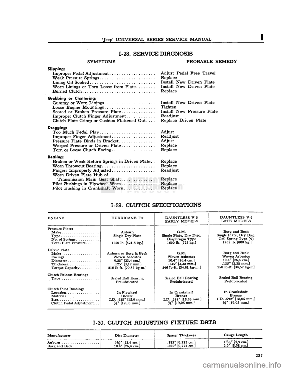
1-28.
SERVICE
DIAGNOSIS
SYMPTOMS
PROBABLE
REMEDY
Slipping:
Improper Pedal Adjustment Adjust Pedal Free
Travel
Weak Pressure Springs Replace
Lining
Oil Soaked Install New Driven Plate
Worn
Linings or
Torn
Loose from Plate Install New Driven Plate
Burned Clutch Replace
Grabbing
or
Chattering:
Gummy or Worn Linings Install New Driven Plate
Loose Engine
Mountings
Tighten Scored or Broken Pressure Plate Install New Pressure Plate
Improper Clutch Finger Adjustment............ Readjust
Clutch
Plate Crimp or Cushion Flattened Out.... Replace Driven Plate
Dragging: Too Much Pedal Play. Adjust Improper Finger Adjustment. Readjust
Pressure Plate Binds in Bracket Adjust
Warped Pressure or Driven Plate Replace
Torn
or Loose Clutch Facing. Replace
Rattling:
Broken or Weak Return Springs in Driven Plate.. Replace
Worn
Throwout Bearing Replace
Fingers Improperly Adjusted Readjust
Worn
Driven Plate Hub of Transmission Main Gear Shaft.............. Replace
Pilot Bushings in Flywheel Worn.
.............
Replace
Pilot Bushing in Crankshaft Worn Replace
1-29.
CLUTCH
SPECIFICATIONS
ENGINE
HURRICANE
F4
DAUNTLESS
V-6
DAUNTLESS
V-6
EARLY
MODELS
LATE
MODELS
Pressure Plate;
Auburn
G.M.
Borg and Beck
Type
Single
Dry Plate
Single
Plate, Dry Disc.
Single
Plate, Dry Disc.
No. of Springs 3 Diaphragm Type
Coil
Spring Type (9)
Total
Plate Pressure 1150 lb.
[521,6
kg.]
1600 lb. [725 kg.] 1765 lb. [800 kg.]
Driven Plate Make
Auburn
or Borg & Beck
G.M.
Borg and Beck
Facings Woven
Asbestos
Woven
Asbestos
Woven
Asbestos
Diameter 9.25" [23,4 cm.] 10.4" [26,4 cm.]
10.4" [26,4 cm.]
Thickness .125" [3,17 mm.] .135" [3,38 mm.]
.135" [3,38 mm.]
Torque Capacity 216 lb-ft.
[29,87
kg-m.]
246 lb-ft.
[34.01
kg-m.]
250 lb-ft.
[34,57
kg-m]
Clutch
Release Bearing: Sealed
Ball
Bearing
.
Type Sealed
Ball
Bearing Sealed
Ball
Bearing Sealed
Ball
Bearing
.
Type
Prelubricated Prelubricated
Prelubricated
Clutch
Pilot Bushing:
In
Crankshaft
In
Flywheel
In
Crankshaft
In
Crankshaft
Material
Bronze Bronze
Bronze
Size.
I.D.
.628" [15,9 mm.]
I.D.
.592"
[18,05
mm.]
I.D.
.592"
[18,05
mm.]
Clutch
Pedal Adjustment. .. W
[19,05
mm.]
%n
[19,05
mm.]
%n
[19,05
mm.]
1-30.
CLUTCH
ADJUSTING
FIXTURE
DATA
Manufacturer Disc Diameter Spacer Thickness Gauge Length
Auburn
9j£"
[23,4 cm.]
10.4" [26,4 cm.] .285"
.305"
0,723
cm.]
0,774
cm.]
mtf
[4,9 cm.]
2.0" [5,08 cm.]
9j£"
[23,4 cm.]
10.4" [26,4 cm.] .285"
.305"
0,723
cm.]
0,774
cm.]
mtf
[4,9 cm.]
2.0" [5,08 cm.]
Page 240 of 376

THREE-SPEED
TRANSMISSION
FIG.
J-l—TRANSMISSION
REMOTE
CONTROL
CJ-5
A,
CJ-6A
1— Stop Screw
2—
Bias
Spring
3—
Gearshift
Lever
4—
Lever
Ball
5—
Steering
Wheel 6—
Horn
Button 7—
Column
and Bearing
8—
End
Huts
9—
Shift
Rod
Ends
10—
Shift
Rod
11—
Shift
Rod
12—
Cross-Shift
Bracket
13—
Control
Shaft
14—
Lubrication
Fitting
15—
Lever
and
Clutch
16—
Adjusting
Yoke
17—
Aligning
Rod 11706
b.
Remove gearshift lever fulcrum pin and the
gearshift lever.
c.
Remove plates on the toe board at the steer
ing
post.
d.
Remove two screws holding remote control
housing to the steering
post
and lift the housing
from
the positioning pin.
e.
Remove the assembly down through the floor
pan.
f. Remove the lower clutch and shift lever from the housing by turning counterclockwise.
g. Remove upper clutch and shift lever in the same
manner.
h. Wash all parts in a suitable cleaning solution.
J-5.
Reassembly of
Remote
Control
•
Refer to
Fig.
J-l
Check
clearance of shift dog which
engages
in slot
of clutches, and if found to be greater than .009" [0,229 mm.] clearance, replace the worn parts.
Assemble upper clutch lever assembly in housing
making
sure that the alignment
hole
in the housing
faces toward the engine.
Turn
the upper lever as
sembly in as far as it
will
go and then back off one
full
turn
until the
hole
in the clutch lever aligns
with
hole
in the housing.
Assemble the lower clutch lever assembly in hous ing until faces of clutches contact then back off
not more than one-half
turn
which should bring
the aligning
hole
in the lever in line with the
hole
in
the housing. If the one-half
turn
does
not bring
the alignment
hole
in proper position, it
will
be
necessary to grind off (square with axis not to exceed .015") [0,397 mm.] the face of the lower
clutch;
in other words, backing off not more than
one-half
turn
from face to face contact
gives
the
proper
clearance of .015" to .031"
[0,397-0,794
mm.]
between
the two clutches.
Assemble the unit to the steering
post
in reverse
order
of dismantling and adjust remote control
rods.
After
assembly, if the shift dog catches on the
edge
of the slot in the clutch when moving the lever up
and
down, disconnect the shift rod at the
transmission
end and either lengthen or shorten it
slightly to correct this condition.
J-6.
TRANSMISSION
REMOVAL
The
following repair procedures given in Par. J-7
through J-ll for the standard
3-speed
transmission
apply
in general to all models listed. Minor dif
ferences
between
models that affect the procedure
are
noted. Procedure for the optional
4-speed
transmission
begins
with Section
J-l.
Removal
is as follows:
a.
Drain
the transmission and transfer case. Re place the
drain
plugs.
b.
Remove the floor pan inspection plate.
c.
Remove the shift lever and shift housing as sembly and its gasket from the transmission. On 240
Page 241 of 376
'Jeep'
UNIVERSAL
SERIES
SERVICE
MANUAL
J
10489
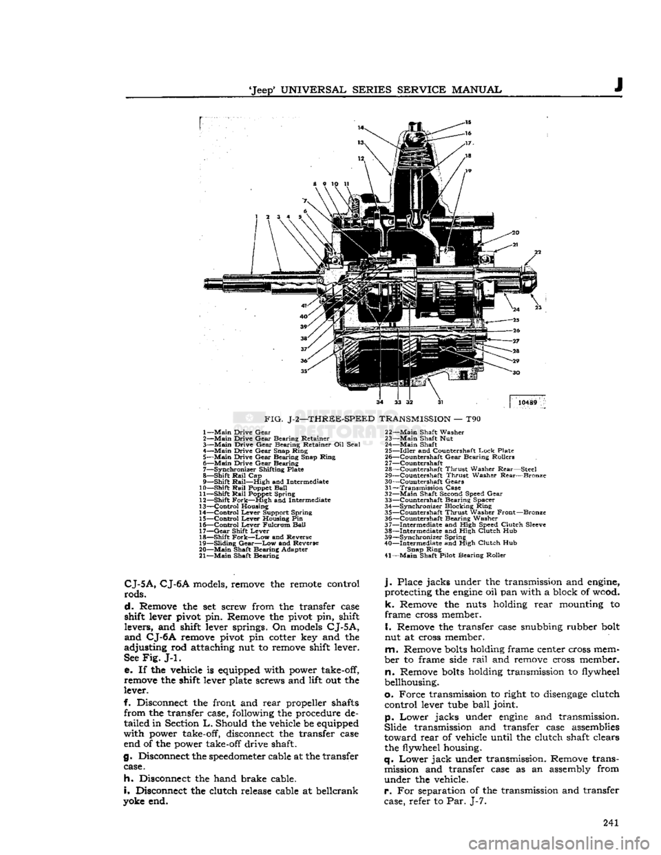
FIG.
J-2—THREE-SPEED
TRANSMISSION
— T90 1—
Main
Drive
Gear
2—
Main
Drive
Gear
Bearing
Retainer
3—
Main
Drive
Gear
Bearing
Retainer Oil
Seal
4—
Main
Drive
Gear
Snap
Ring
5—
Main
Drive
Gear
Bearing
Snap
Ring
6—
Main
Drive
Gear
Bearing
7—
Synchronizer
Shifting Plate
8—
Shift
Rail
Cap
9—
Shift
Rail—High
and Intermediate
10—
Shift
Rail
Poppet
Ball
11—
Shift
Rail
Poppet
Spring
12—
Shift
Fork—High
and Intermediate
13—
Control
Housing
14—
Control
Lever
Support
Spring
15—
Control
Lever
Housing Pin
16—
Control
Lever
Fulcrum
Ball
17—
Gear
Shift
Lever
18—
Shift
Fork—Low
and Reverse
19—
Sliding
Gear—Low
and Reverse
20—
Main
Shaft
Bearing
Adapter
21—
Main
Shaft
Bearing
22—
Main
Shaft
Washer
23—
Main
Shaft Nut
24—
Main
Shaft
25—
Idler
and Countershaft
Lock
Plate
26—
^Countershaft
Gear
Bearing
Rollers
2
7—Countershaft
28—
Countershaft
Thrust
Washer
Rear—Steel
29—
Countershaft
Thrust
Washer
Rear—Bronze
30—
Countershaft
Gears
31—
Transmission
Case
32—
Main
Shaft Second Speed
Gear
33—
Countershaft
Bearing
Spacer
34—
Synchronizer
Blocking
Ring
35—
Countershaft
Thrust
Washer
Front—Bronze
36—
Countershaft
Bearing
Washer
37—
Intermediate
and High Speed
Clutch
Sleeve
38—
Intermediate
and High
Clutch
Hub
39—
Synchronizer
Spring
40—
Intermediate
and High
Clutch
Hub
Snap
Ring
41—
Main
Shaft Pilot
Bearing
Roller
CJ-5A,
CJ-6A
models, remove the remote control
rods.
d.
Remove the set screw from the transfer case
shift lever pivot pin. Remove the pivot pin, shift
levers,
and shift lever springs. On models
CJ-5A,
and
CJ-6A
remove pivot pin cotter key and the
adjusting
rod attaching nut to remove shift lever.
See
Fig.
J-l.
e. If the vehicle is equipped with power take-off,
remove the shift lever plate screws and lift out the
lever.
f. Disconnect the front and
rear
propeller shafts
from
the transfer case, following the procedure de
tailed
in Section
L.
Should the vehicle be equipped
with
power take-off, disconnect the transfer case end of the power take-off drive shaft.
g. Disconnect the
speedometer
cable at the transfer case.
h.
Disconnect the hand brake cable.
i.
Disconnect the clutch release cable at beilcrank
yoke end.
j.
Place
jacks
under the transmission and engine,
protecting the
engine
oil pan with a block of wood,
k.
Remove the nuts holding
rear
mounting to
frame
cross member.
I.
Remove the transfer case snubbing rubber bolt
nut at cross member.
m.
Remove
bolts
holding frame center cross mem
ber
to frame side
rail
and remove cross member,
n.
Remove
bolts
holding transmission to flywheel
bellhousing.
o.
Force
transmission to right to
disengage
clutch
control
lever tube
ball
joint.
p.
Lower
jacks
under
engine
and transmission.
Slide
transmission and transfer case assemblies
toward
rear
of vehicle until the clutch shaft clears the flywheel housing.
q.
Lower
jack
under transmission. Remove trans mission and transfer case as an assembly from
under
the vehicle.
r.
For separation of the transmission and transfer
case, refer to Par. J-7. 241
Page 265 of 376
'Jeep'
UNIVERSAL SERIES SERVICE
MANUAL
Jl
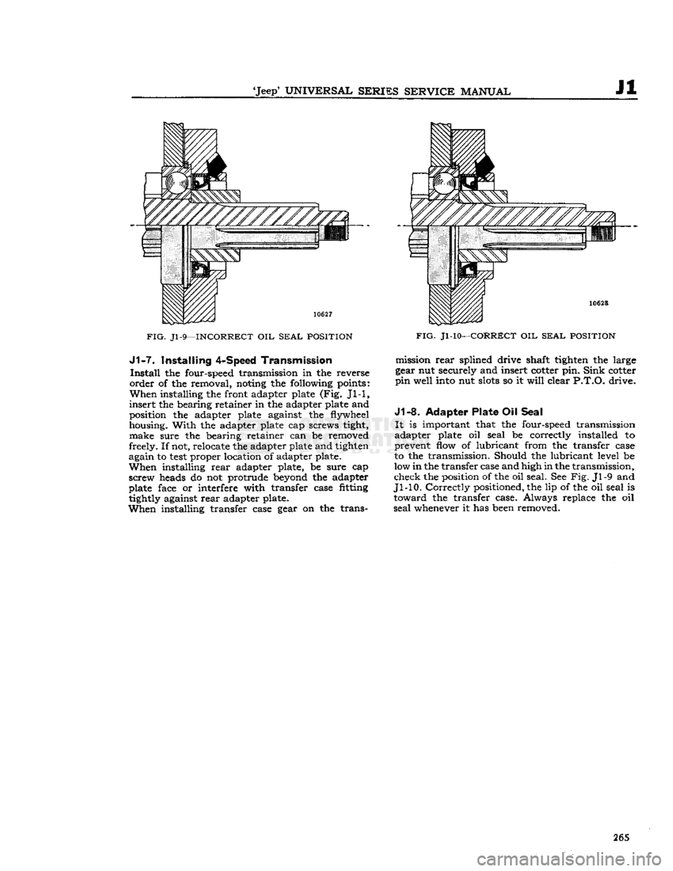
FIG.
Jl-9—INCORRECT
OIL
SEAL POSITION J1-7.
Installing
4-Speed
Transmission
Install
the four-speed transmission in the reverse
order
of the removal, noting the following points:
When
installing the front adapter plate (Fig. Jl-1,
insert
the bearing retainer in the adapter plate and
position the adapter plate against the flywheel
housing.
With
the adapter plate cap screws tight, make sure the bearing retainer can be removed
freely. If not, relocate the adapter plate and tighten
again to
test
proper location of adapter plate.
When
installing
rear
adapter plate, be sure cap
screw heads do not protrude beyond the adapter
plate face or interfere with transfer case fitting
tightly against
rear
adapter plate.
When
installing transfer case gear on the trans-
FIG.
Jl-10—CORRECT
OIL
SEAL POSITION
mission
rear
splined drive shaft tighten the large
gear nut securely and insert cotter pin.
Sink
cotter
pin
well into nut
slots
so it
will
clear
P.T.O.
drive.
J1-8.
Adapter Plate
Oil
Seal
It
is important that the four-speed transmission
adapter plate oil seal be correctly installed to
prevent flow of lubricant from the transfer case
to the transmission. Should the lubricant level be
low in the transfer case and high in the transmission,
check the position of the oil seal. See Fig. Jl-9 and
Jl-10.
Correctly
positioned, the lip of the oil seal is
toward
the transfer case. Always replace the oil
seal
whenever it has been removed. 265