1953 JEEP CJ Wheel bearing
[x] Cancel search: Wheel bearingPage 75 of 376

'Jeep'
UNIVERSAL SERIES
SERVICE
MANUAL
Dl
DAUNTLESS
V-6
ENGINE
Contents
SUBJECT
PAR.
SUBJEC
GENERAL
.... . . Dl-1 Oil Pump Cl(
ENGINE DESCRIPTION
D1-2
Engine
Mounts Dl-3
ENGINE REMOVAL
Dl-4
ENGINE DISASSEMBLY
Dl-5
Alternator
and Fan Belt Dl-11
Camshaft
.... Dl-26
Cooling Fan and Water Pump.
......
.Dl-12
Crankshaft
Front Oil Seal .Dl-21
Crankshaft
Pulley D1-17
Crankshaft
Vibration Damper Dl-18
Cylinder
Head Assembly Dl-24
Distributor
Dl-9
Exhaust
Manifold .Dl-8
Flywheel
Dl-28
Flywheel
Housing and
Clutch
Dl-27
Fuel
Pump. ... . .Dl-10
Intake
Manifold and
Carburetor
Assembly.
.............
.Dl-7
Main
Bearing and Crankshaft. Dl-32 Mounting Engine on Engine Stand. . . . .Dl-6
Oil
Dipstick. Dl-16
Oil
Filter
Dl-13
Oil
Pan.. ...
.......
.Dl-29
Oil
Pressure Sending Unit Dl-15
Oil
Pump Dl-19
Oil
Pump Intake Pipe and Screen Dl-30
Piston and Rod Assembly. Dl-31
Push
Rod and Valve
Lifter.
.Dl-25
Rocker
Arm Cover Dl-23
Starter
Motor Dl-14
Timing
Chain
and Sprocket Dl-22
Timing
Chain
Cover Dl-20
ENGINE CLEANING, INSPECTION AND REPAIR
. . ... .Dl-33
Camshaft
Cleaning and Inspection Dl-55
Connecting Rod Bearing Inspection
and
Fitting .Dl-49
Crankshaft
Cleaning Dl-38
Crankshaft
Inspection and Repair Dl-39
Crankshaft
Main Bearing Cleaning
and
Inspection Dl-41
Crankshaft
Main Bearings. Dl-40
Crankshaft
Pulley Inspection. Dl-70
Crankshaft
Vibration Damper Inspection. D1-69
Cylinder
Block .Dl-34
Cylinder
Block Cleaning Dl-35
Cylinder
Block Inspection Dl-36
Cylinder
Block Repair. .Dl-37
Cylinder
Head and Valve Repair .Dl-63
Cylinder
Head and Valve Cleaning
and
Inspection.. . .Dl-62
Flywheel
Cleaning and Inspection Dl-52
Flywheel
Housing Cleaning
and
Inspection Dl-54
Hydraulic
Valve
Lifter
Leakdown Test. .Dl-57
Main
Bearing Fitting or
Shim
Stock Dl-42, Dl-43
Oil
Pan Cleaning and Inspection .Dl-51
PAR.
and
Inspection. .... .Dl-68
Oil
Pump Intake and Screen Cleaning. . .Dl-50
Piston and Rod Assembly.
...........
.Dl-48
Piston and Rod Cleaning and Inspection.D1-45
Piston and Rod Disassembly Dl-44
Piston Fitting Dl-46
Piston Ring Fitting. .Dl-47
Ring
Gear
Replacement. .Dl-53
Rocker
Arm Assembly. Dl-60
Rocker
Arm Cleaning and Inspection. . .Dl-59
Rocker
Arm Cover Cleaning
and
Inspection D1-65
Rocker
Arm Disassembly .Dl-58
Timing
Chain
and Sprocket Inspection. . .Dl-66
Timing
Chain
Cover Cleaning
and
Inspection.. . Dl-67
Valve
Installation D1-64
Valve
Lifter
and Push Rod
Cleaning
and Inspection. . Dl-56
Valve
Removal Dl-61
ENGINE REASSEMBLY
Dl-71
Alternator
and Fan Belt Dl-96
Camshaft
Dl-80
Clutch
and Flywheel Housing Dl-79
Cooling Fan.. . .Dl-95
Crankshaft
End Play Check. . Dl-74
Crankshaft
Front Oil Seal Dl-85
Crankshaft
Pulley Dl-89
Crankshaft
Vibration Damper Dl-88
Cylinder
Block and Crankshaft
Rear
Oil Seals Dl-72
Cylinder
Head Assembly .Dl-82
Distributor
Dl-99
Exhaust
Manifold Dl-98
Flywheel
.Dl-78
Fuel
Pump.. .. . Dl-97
Intake
Manifold and Carburetor Assembly Dl-101
Main
Bearing and
Crankshaft
Installation
.
Dl-73
Oil
Filter
Dl-93
Oil
Level
Dipstick Dl-90
Oil
Pan Dl-77
Oil
Pressure Sending Unit Dl-91
Oil
Pump.. .Dl-87
Oil
Pump Intake and Screen Assembly. .Dl-76
Piston and Rod Installation Dl-75
Rocker
Arm Cover. Dl-83
Spark
Plugs.. Dl-100
Starter
Motor Dl-92
Timing
Chain
and Sprocket.
..........
.Dl-84
Timing
Chain
Cover Dl-86
Valve
Lifter
and Push Rod Dl-81
Water
Pump. Dl-94
ENGINE INSTALLATION
Dl-102
FINAL
IN-VEHICLE
ADJUSTMENTS.
D1-103
SERVICE
DIAGNOSIS
Dl-104
ENGINE SPECIFICATIONS
. .Dl-105 75
Page 77 of 376

'Jeep'
UNIVERSAL SERIES SERVICE
MANUAL
Dl
©©©©©©©©©
12697
FIG.
Dl-1—DAUNTLESS
V-6
ENGINE, SIDE SECTIONAL VIEW
1—
Fan
Blade
2—
Fan
Spacer
3—Fan
Pulley
4—
Water
Pump 5—
Timing
Chain
Cover
6—
Camshaft
Sprocket
7—
Thermostat
Bypass Hose
8—
Thermostat
Housing
9—
Thermostat
10—
Carburetor
11—
Intake
Manifold
12—
Rocker
Arm Cover 13—
Cylinder
Block 14—
Push
Rod
15—
Camshaft
16—
Flywheel
17—
Clutch
Pressure Plate
18—
Clutch
Driven Plate
19—
Clutch
Pilot Bearing
20—
Oil
Seal Packing
21—
Rear
Main
Bearing Shell
22— Connecting Rods
23—
Rear
Center
Main
Bearing Shell
24—
Oil
Screen
25—
Oil
Screen Pipe and Housing
26—
Oil
Pan 27—
Front
Center
Main
Bearing Shell
28—
Crankshaft
29—
Front
Main
Bearing Shell
30—
Timing
Chain
31—
Crankshaft
Sprocket
32—
Oil
Slinger
33—
Oil
Shedder 34 Oil Shedder Packing
35—
-Woodruff
Key
36—
"Vibration
Damper
37—
Crankshaft
Pulley
38—
Fan
Belt matic adjuster, to prevent lash in the valve operat
ing linkage. Hydraulic valve lifters also provide
a
cushion of oil to absorb operating shocks. As shown in Fig. Dl-3, all parts of a hydraulic lifter
are
housed in the body, which is the cam follower.
At
the beginning of valve operation, the valve lifter body rests on the camshaft base circle.
Plunger
spring tension prevents lash clearances in the valve linkage.
As
the camshaft forces the valve lifter body up
ward,
both oil in the lower chamber and check
ball
spring
tension firmly seat the check ball against the plunger to prevent appreciable
loss
of oil from
the lower chamber. Oil pressure forces the plunger
upward,
with the body, to operate the valve linkage.
As
the camshaft rotates to closed-valve position, the valve spring forces the linkage and lifter down
ward.
When the
engine
valve seats, the linkage
parts
and plunger stop, but the plunger spring forces
the body downward .002" to .003"
[0,050
a
0,076
mm.] until it again rests on the camshaft base
circle.
Oil pressure then forces the check ball away
from
its seat and allows passage of oil past the check ball into the lower chamber.
This
replaces
the slight amount of oil lost by leakage. During
the valve opening and closing operation, a very
slight amount of oil escapes
between
plunger and body, and returns to the crankcase.
This
slight
loss
of oil (leak-down) is beneficial. It provides a
gradual
change of oil in the valve lifter; fresh oil
enters the lower chamber at the end of each cycle
of operation. 77
Page 82 of 376
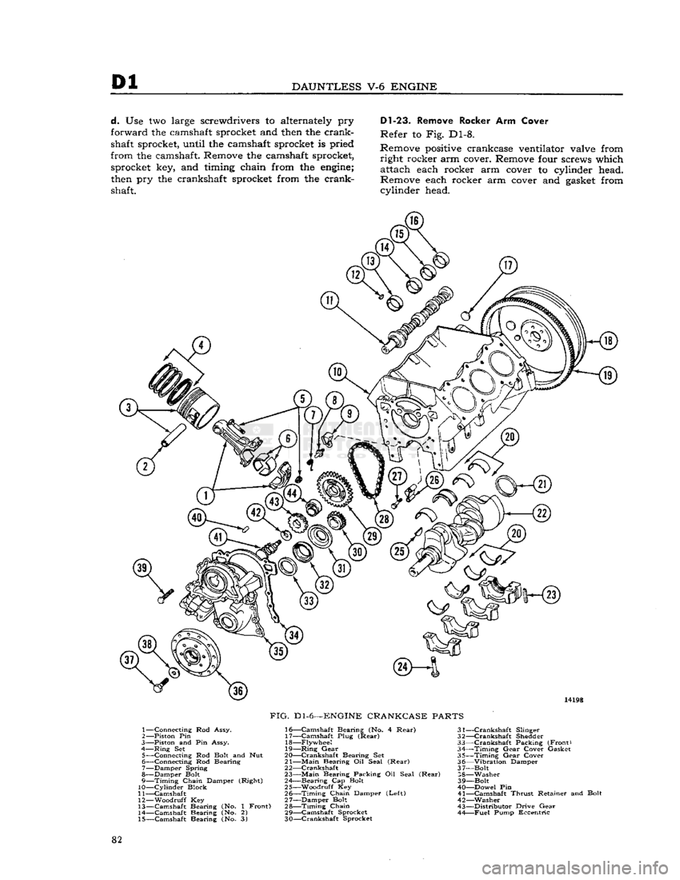
Dl
DAUNTLESS
V-6
ENGINE
d.
Use two large screwdrivers to alternately pry
forward the camshaft sprocket and
then
the crank
shaft sprocket, until the camshaft sprocket is pried
from the camshaft. Remove the camshaft sprocket, sprocket key, and timing chain from the
engine;
then
pry the crankshaft sprocket from the crankshaft.
Dl-23.
Remove Rocker Arm Cover
Refer to Fig. Dl-8.
Remove
positive
crankcase ventilator valve from right rocker arm cover. Remove four screws which attach each rocker arm cover to cylinder head.
Remove each rocker arm cover and
gasket
from cylinder head. 14198
FIG.
Dl-6—ENGINE
CRANKCASE
PARTS
1— Connecting Rod Assy.
2— —Piston Pin
3—
Piston and Pin Assy.
4—
Ring
Set 5— Connecting Rod
Bolt
and Nut
6— Connecting Rod Bearing
7— Damper Spring
8— Damper
Bolt
9—
Timing
Chain Damper (Right)
10—
Cylinder
Block
11— Camshaft
12—
Woodruff
Key
13— Camshaft Bearing (No. 1 Front) 14— Camshaft Bearing (No. 2)
15— Camshaft Bearing (No. 3) 16—
Camshaft
Bearing (No. 4
Rear)
31-
17—
Camshaft
Plug
(Rear)
32-18—
Flywheel
33-
19—
Ring
Gear
34-
20— Crankshaft Bearing Set 35-
21—
Main
Bearing Oil Seal
(Rear)
36-
2 2—Crankshaft 3 7-
23—
Main
Bearing Packing Oil Seal
(Rear)
28-
24— Bearing Cap
Bolt
39-
25— Woodruff Key 40-
26—
Timing
Chain Damper
(Left)
41-
27— Damper Bolt 42- 28—
Timing
Chain
43-
29—
Camshaft
Sprocket 44-
30— Crankshaft Sprocket
—Crankshaft
Slinger
—Crankshaft
Shedder
—Crankshaft
Packing (Front)
—Timing
Gear
Cover Gasket
—Timing
Gear
Cover
—Vibration
Damper
-Bolt
-Washer
-Bolt
—Dowel Pin
-Camshaft
Thrust
Retainer and Bolt
—Washer
-Distributor
Drive
Gear
—Fuel
Pump Eccentric
82
Page 83 of 376
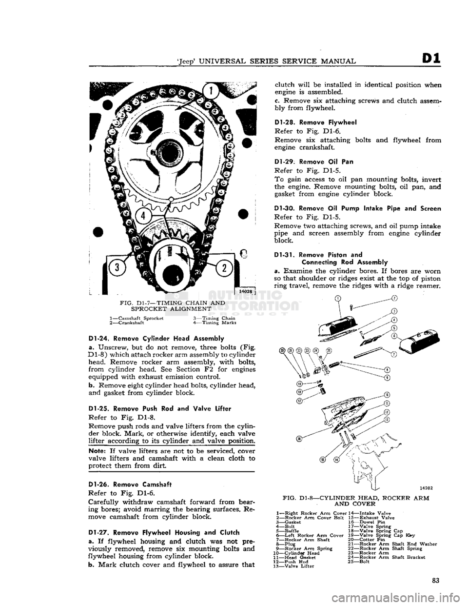
'Jeep'
UNIVERSAL
SERIES SERVICE
MANUAL
Dl
14028
j
FIG.
D1-7—TIMING
CHAIN
AND
SPROCKET ALIGNMENT 1—
Camshaft Sprocket
2—
Crankshaft
3—Timing
Chain
Timing
Marks
Dl-24.
Remove
Cylinder
Head Assembly
a.
Unscrew, but do not remove, three
bolts
(Fig.
Dl-8)
which attach rocker
arm
assembly to cylinder
head.
Remove rocker arm assembly, with bolts,
from
cylinder head. See Section F2 for
engines
equipped with exhaust emission control.
b. Remove
eight
cylinder head bolts, cylinder head,
and
gasket from cylinder block.
Dl-25.
Remove Push Rod and Valve
Lifter
Refer
to Fig. Dl-8. Remove push rods and valve lifters from the
cylin
der
block.
Mark,
or otherwise identify, each valve
lifter
according to its cylinder and valve position.
Note:
If valve lifters are not to be serviced, cover
valve lifters and camshaft with a clean cloth to
protect them from dirt
Dl-26.
Remove Camshaft
Refer
to Fig. Dl-6.
Carefully
withdraw camshaft forward from bear
ing bores; avoid marring the bearing surfaces. Re
move
camshaft from cylinder block.
Dl-27.
Remove Flywheel Housing and
Clutch
a.
If flywheel housing and clutch was not pre
viously removed, remove six mounting
bolts
and
flywheel housing from cylinder block.
b.
Mark
clutch cover and flywheel to assure that
clutch
will
be installed in identical position when
engine
is assembled.
c. Remove six attaching screws and clutch assem
bly from flywheel.
D1-28. Remove Flywheel
Refer
to Fig. Dl-6.
Remove six attaching
bolts
and flywheel from
engine
crankshaft.
Dl-29.
Remove Oil Pan
Refer
to Fig. Dl-5.
To
gain access to oil pan mounting bolts, invert
the
engine.
Remove mounting bolts, oil pan, and gasket from
engine
cylinder block.
Dl-30.
Remove Oil Pump Intake Pipe and Screen
Refer
to Fig. Dl-5.
Remove two attaching screws, and oil pump intake
pipe and screen assembly from
engine
cylinder block.
Dl-31.
Remove Piston and
Connecting
Rod Assembly
a.
Examine the cylinder bores. If bores are worn
so that shoulder or ridges exist at the top of piston
ring
travel, remove the ridges with a ridge reamer.
FIG.
Dl-8-
-CYLINDER HEAD,
AND COVER
ROCKER
ARM
1—
—Right
Rocker
Arm
Cover
2—
Rocker
Arm
Cover
Bolt
3—
Gasket
4—
Bolt
5—
Baffle
6—
Left
Rocker
Arm
Cover
7—
Rocker
Arm Shaft
8—Plug
9—
Rocker
Arm Spring
10—
Cylinder
Head
11—
Head
Gasket
12—
Push
Rod
13—
Valve
Lifter
14—
Intake
Valve
15—
Exhaust
Valve
16—
Dowel
Pin
17—
Valve
Spring 18—
Valve
Spring Cap
19—
Valve
Spring Cap Key
20—
Cotter
Pin
21—
Rocker
Arm Shaft End Washer
22—
Rocker
Arm Shaft Spring
23—
Rocker
Arm
24—
Rocker
Arm Shaft
Bracket
25—
Bolt
83
Page 84 of 376

Dl
DAUNTLESS
V-6
ENGINE
This
will
prevent damage to piston rings or
crack
ing piston lands during removal.
b. Use a silver pencil or quick-drying paint to mark
the cylinder number on all pistons, connecting rods,
and
caps. Starting at the front end of the crankcase,
the cylinders in the right bank are numbered 2-4-6
and
in the
left
bank are numbered
1-3-5.
c. Remove cap and lower connecting rod bearing
half
from No. 1 connecting rod.
d.
Push the piston and rod assembly away from
the crankshaft and remove it from top of cylinder bore. Then install cap and lower bearing half on
connecting rod.
e. Remove each connecting rod and piston as sembly as described in c and d, above.
FIG.
D1-9—CRANKSHAFT
MAIN
BEARING
CAPS
1—Thrust
Bearing
D1-32.
Remove
Main
Bearing and Crankshaft
a.
This
engine
has four crankshaft main bearings.
Front
to
rear,
they are numbered 1 to 4. Refer to
Fig.
Dl-9. With a silver pencil or quick-drying
paint, mark the bearing number on each main bearing cap.
b. Remove two
bolts
which secure first (front)
main
bearing cap to
engine
cylinder block. With
a
lifting bar, carefully pry the cap from the crank shaft and block. Be careful not to damage the cap,
block or crankshaft. Remove the bearing cap, with
lower main bearing half, from the cylinder block.
Keep
bearing half and cap
together.
Similarly, remove the next two main bearing caps with lower
main
bearing halves. To remove
rear
main bearing
cap,
use
rear
main bearing remover bolt W-323.
c. Remove the fabric seal from inside diameter of
fourth (rear) main bearing cap, and remove neo-
prene composition seal from outer surface of this
bearing cap. Discard both seals.
d.
Lift
and remove the crankshaft from
engine
cylinder
block. Do not remove upper main bearing
halves from block or lower main bearing halves
from
caps at this time. Mount main bearing caps
in
their original positions.
Dl-33.
ENGINE
CLEANING,
INSPECTION,
AND
REPAIR
The
cleaning, inspection, and repair procedures
detailed herein are recommended to be followed
when a
complete
engine
overhaul is to be made
with the
engine
out of the vehicle. These instruc
tions
can generally be applied individually with the
engine
in the vehicle. Wherever the procedure dif
fers due to the
engine
being in the vehicle, the necessary special instructions are provided. Inspec
tion and repair instructions are included to cover
the cylinder block, cylinder head, crankshaft and bearings, connecting rods and bearings, oil pump,
valves and tappets, pistons and rings, flywheel,
timing gears, and the camshaft and bearings. In
addition, fitting operations for
these
engine
com
ponents
are included.
D1-34.
Cylinder Block
The
cylinder block must be cleaned thoroughly, inspected, and repaired as necessary, as described
below.
Dl-35.
Cylinder Block Cleaning
Steam-clean the cylinder block, or clean it with
a
suitable cleaning solvent A scraper can be used
to remove
hard
deposits, but do not score machined
surfaces. Be certain that oil passages, valve cham
bers,
crankcase, and cylinder walls are free from sludge, dirt, and carbon deposits. After cleaning,
dry
the cylinder block carefully with compressed
air.
Dl-36.
Cylinder Block Inspection
a.
Inspect cylinder walls visually for scoring,
roughness, or ridges which indicate excessive wear.
Check
cylinder bores for taper and out-of-round
with an accurate cylinder
gauge.
Measure eact bore at top, middle and bottom, both parallel tc
and
at right
angles
to the centerline of the
engine
The
diameter of the cylinder bores at any poin
FIG.
Dl-10—MEASURING
CYLINDER
BORE
1—Telescope Gauge [90*
From
Piston Pin]
84
Page 90 of 376

DAUNTLESS
V-6
ENGINE
Note:
The rib on
edge
of cap and the conical
boss
on web of connecting rod must be toward
rear
of
engine
in all connecting rod assemblies of left
cyl
inder
bank and toward front of
engine
in all connecting rod assemblies of right cylinder bank.
Dl-50.
Oil
Pump Intake
and
Screen Cleaning
a.
Pry screen from housing and examine for clog
ging due to deposit of sludge or other foreign
material.
b.
Clean
the screen and housing thoroughly in sol
vent; dry with compressed air.
c.
Install
screen in housing.
Dl-51.
Oil Pan Cleaning and Inspection
Inspect
the oil pan for corrosion, dents, leaks, and
other damage. Inspect its mounting flange carefully
for damage or distortion to be certain that it
will
give
a
good
seal.
Dl-52.
Flywheel Cleaning
and
Inspection
Clean
the flywheel with suitable cleaning solvent;
dry
with compressed air. Inspect clutch face for
burned
or scuffed condition and for rivet grooves.
Inspection
for run out or improper mounting is de
scribed
in installation procedure.
Inspect
teeth
of the flywheel
ring
gear for
burrs,
nicks,
and minor distortion. If necessary and pos
sible, use a small emery wheel to remove
burrs
and
reshape teeth. If gear
teeth
are broken,
cracked,
seriously
burred
or deformed, the
ring
gear must be replaced.
Dl-53.
Ring Gear Replacement
a.
Drill
a
hole
between
two
ring
gear teeth; then
split
the gear with a cold chisel. Be careful not to
damage
ring
gear shoulder or seat surfaces of fly
wheel.
b.
Polish several
spots
on the new
ring
gear to be
installed.
With
a hot plate or slowly moving torch,
heat the new
ring
gear until polished
spots
become
blue, about
600°F.
[312°C.].
Caution:
Do not heat the
ring
gear to a temperature
greater than
800°F.
[424°C.].
Excessive heat
will
destroy heat treatment given to
ring
gear during
manufacture.
c.
Quickly
install
ring
gear on flywheel. Chamfered
edge
of
ring
gear must be toward
ring
gear shoulder
of flywheel. Be certain that
ring
gear is seated prop
erly.
Allow
ring
gear to cool slowly, so that it
will
be held tightly in place.
Dl-54.
Flywheel Housing Cleaning and Inspection
Both
flywheel and clutch are enclosed by a fly
wheel housing. Its front surface is bolted to the
engine
cylinder block, and its
rear
surface acts as
front
support to the transmission.
Clean
the fly wheel housing with a suitable cleaning solvent; dry
with
compressed air. Inspect front and
rear
surfaces
for distortion and improper alignment with each
other;
these
planes must be
parallel
to assure
proper
alignment
between
engine
and transmission.
Dl-55.
Camshaft Cleaning
and
Inspection
Clean
both camshaft and camshaft bearing surfaces
with
a suitable cleaning solvent; dry with com
pressed air.
Note:
The steel-backed babbitt-lined camshaft
bearings are pressed into the crankcase.
From
front
to
rear,
each bearing is .030" [0,76 mm.] smaller
in
diameter than the preceding bearing.
From
front
to
rear,
each camshaft
journal
is correspondingly
smaller
in diameter.
The
camshaft bearings must be line reamed to
proper
diameter after being pressed into crankcase.
Since
this operation requires special reaming equip
ment, the original bearings should be retained un
less
they are severly damaged. Slightly scored cam
shaft bearings are satisfactory if the surfaces of camshaft journals are polished, bearings are
polished to remove
burrs,
and
radial
clearance
between
camshaft and bearings is within .0015"
to .004" [0,038 a 0,102 mm.].
Dl-56.
Valve Lifter
and
Push
Rod
Cleaning and Inspection
a.
Examine the cam contact surface at lower end of each valve lifter body. If surface is excessively
worn,
galled, or otherwise damaged, discard the
valve lifter. Also examine the mating camshaft
lobe
for excessive wear or damage.
b.
Disassemble one or two valve lifters, as de
scribed
below, and inspect them for
dirt
or
varnish.
If
they are dirty or have a varnish deposit, clean
and
inspect all twelve valve lifters. Otherwise,
service
only
those
valve lifters which do not operate
properly.
c.
To disassemble each valve lifter, depress the
push
rod seat with a push rod, and remove the
plunger retainer from the valve lifter body with
a
retainer remover. Remove push rod seat and
plunger from valve lifter body. If plunger sticks
in
valve lifter body, place body in large end of
a
plunger remover tool, with plunger downward.
While
holding lifter with thumb, rap the open end
of remover against a block of wood with just enough force to jar the plunger from body. Refer to
Figs.
Dl-20, Dl-22 and Dl-23.
d.
Drain
oil from valve lifter and remove the check
valve retainer,
ball,
valve spring, and plunger
spring.
e. Keep all parts of each valve lifter separated
during
part cleaning and inspection. The valve
lifter
body and plunger are selectively fitted to each other and must not be interchanged with parts
of other valve lifters.
f. Rinse all valve lifter parts in kerosene to remove as much oil as possible.
This
will
reduce contamina
tion of the cleaning solvent. Immerse all parts in cleaning solvent for approximately one hour. The
time required
will
depend on varnish
deposits
and
effectiveness
of the solvent. After the varnish has
dissolved or has
softened
sufficiently to permit re
moval
by wiping, allow parts to
drain.
Varnish
can
then be cleaned from the valve lifter body
with
a
brush.
Rinse the parts in kerosene to dissolve 90
Page 97 of 376

'Jeep'
UNIVERSAL
SERIES SERVICE
MANUAL
Dl
size have
been
selected. If necessary, check or
select
connecting rod bearings as described in Par. Dl-49.
Note:
When a piston and connecting rod assembly
is properly installed, the oil spurt
hole
in the con necting rod
will
face the camshaft. The rib on the
edge
of the bearing cap
will
be on the same side
as the conical
boss
on the connecting rod web;
these
marks (rib and boss)
will
be toward the other
connecting rod on the same crankpin. The notch
on the piston
will
face the front of the
engine.
a.
Be certain that cylinder bores, pistons, connect
ing rod bearings and crankshaft journals are absolutely clean. Coat all bearing surfaces with
engine
oil.
b. Before installing a piston and connecting rod as
sembly into its bore, rotate the crankshaft so that
the corresponding crankpin is moved downward, away from the cylinder bore.
c. Remove bearing cap from connecting rod. With
upper bearing half seated in connecting rod, install connecting rod guides. These
guides
hold the upper
bearing half in place and prevent damage to the
crankshaft
crankpin during installation of the con
necting rod and piston assembly.
d.
Be certain that the gap in the oil ring rails faces
upward,
toward center of
engine.
Gaps of the com
pression rings shall not be aligned with each other
or
with the oil ring
rails.
e. Lubricate the piston and rings. Compress the
rings with a suitable piston ring compressor; install
the piston and connecting rod assembly from top of cylinder bore. Refer to Fig. Dl-33.
f.
Install
bearing cap, with lower bearing half, on connecting rod. Torque bolt nuts to 30 to 40 lb-ft. [4,1 a 5,5 kg-m.].
g.
Install
all other piston and connecting rod as
semblies in same manner.
h.
Check
end clearance
between
connecting rods
on each crankpin with a feeler
gauge.
Clearance should be .005,/ to .012" [0,127 a
0,305
mm.].
Dl-76.
Install
Oil
Pump
Intake
Pipe
and
Screen Assembly
Check
mating surfaces of oil pump intake pipe
and
engine
cylinder block to be certain that they
are
clean. Secure the pipe and screen assembly,
with a new gasket, to
engine
cylinder block with two attaching screws. See Fig. Dl-34. Torque screws 6 to 9 lb-ft. [0,83 a 1,24 kg-m.].
Dl-77.
Install
Oil Pan
Refer
to Fig. Dl-35.
Be
certain the flange surface of oil pan and cor
responding surface of
engine
cylinder block are
clean.
Install
a new oil pan gasket on the cylinder
block.
Secure
oil pan to cylinder block with mount ing bolts. Torque
bolts
10 to 15 lb-ft [1,4 a 2,1
kg-m.].
Dl-78.
Install
Flywheel
Refer
to Fig. Dl-7.
a.
Check
flywheel flange of
engine
crankshaft and corresponding surface of flywheel to
be
certain that
FIG.
Dl-33—INSTALLING
PISTON
AND
CONNECTING
ROD
ASSEMBLY
1—Ring
Compressor
FIG.
Dl-34-^-OIL
PUMP
INTAKE PIPE
AND
SCREEN
INSTALLATION
1—Pipe and Screen
97
Page 99 of 376

'Jeep'
UNIVERSAL SERIES SERVICE
MANUAL
Dl
both are clean. Any foreign material on either of
these
surfaces
will
cause flywheel run out and en
gine
vibration. Position flywheel to crankshaft and
secure with six mounting bolts. Torque mounting
bolts
50 to 65 lb-ft. [6,91 a 8,98 kg-m.].
Note:
Flywheel mounting
bolts
are unevenly
spaced so that flywheel can be installed in only
one position.
This
assures correct balance of fly
wheel and crankshaft.
b.
Mount a
dial
indicator on flywheel housing
flange of cylinder block and index its plunger to
the flywheel surface. Measure flywheel run out.
Maximum
allowable run out is .015"
[0,381
mm.].
Dl-82.
Install
Cylinder
Head Assembly
Refer
to Fig. Dl-9.
a.
Wipe cylinder head face of
engine
cylinder
block, and be certain no foreign material has fallen
into the cylinder bores, bolt holes, or in the valve
lifter
area.
It is
good
practice to clean out bolt
holes
with compressed air.
b.
Install
a new cylinder head gasket on the
cylin
der
block. Dowels in the block
will
hold the gasket
in
position. Always handle gaskets carefully to
avoid
kinking or damage to the surface treatment
of the gasket. Apply Perfect Seal Aerosol
Spray
Sealer
Part
No.
994757
on cylinder head gaskets.
Dl-79.
Install
Clutch
and Flywheel Housing
a.
Note
marks made on clutch assembly and fly
wheel during
engine
disassembly. Position clutch
assembly to flywheel, according to
marks,
and
fasten
loosely
with six attaching bolts. Torque
bolts
in rotation, one
turn
at a time, to 30 to 40 lb-ft. [4,1 a 5,5 kg-m.].
b.
Engage fork of clutch linkage to clutch and
position flywheel housing to
engine
cylinder block.
Secure
housing to block with six mounting bolts.
Torque
bolts
30 to 40 lb-ft. [4,1 a 5,5 kg-m.].
D1-80.
Install
Camshaft
Insert
camshaft into camshaft bearings of
engine
cylinder
block carefully to avoid damage to bear
ing surfaces. Make certain camshaft journals are
properly
seated in bearings.
12695
FIG.
D1-36—CAMSHAFT
AND
VALVE LINKAGE
1—
Rocker
Arm
2—
Push
Rod 3—
Valve
Lifter
4—
Camshaft
14203
FIG.
Dl-37—CYLINDER
HEAD
BOLT TIGHTENING SEQUENCE c.
Clean
gasket surface of cylinder head and care
fully
place on the
engine
block dowel pins.
d.
Clean
and lubricate the cylinder head
bolts
with
a
sealing compound
(Part
No. 994757, or equiv
alent).
e.
Install,
and alternately tighten the head bolts,
a
little at a time, in the sequence shown in Fig.
Dl-37.
Torque
bolts
65 to 85 lb-ft. [9,0 a 11,8
kg-m.].
f.
Tilt
the rocker arms toward the push rods and locate the top of each push rod in its rocker arm
seat.
g.
Mount the rocker arm and shaft assembly, tightening the bracket
bolts
a little at a time.
Torque
the bracket
bolts
25 to 35 lb-ft. [3,5 a 4,8
kg-m.].
Do not overtighten.
h.
See Section Fl and F2 for
engines
equipped
with
exhaust emission control.
D1-81.
Install
Valve Lifter
and Push Rod
Make
certain valve lifter guide
holes
and adjacent
area
of cylinder block are clean.
Liberally
lubricate
the camshaft and valve lifter bores with
engine
oil,
and install valve lifters.
Each
valve lifter must slide freely in its guide hole. See Fig. Dl-36.
Dl-83.
Install
Rocker Arm Cover
Install
a new gasket on each rocker arm cover.
Secure
each rocker arm cover to corresponding
cylinder
head with four attaching screws.
Install
the positive crankcase ventilation valve on right
rocker
arm cover. 99