1900 MITSUBISHI DIAMANTE hood release
[x] Cancel search: hood releasePage 371 of 408

BODYANDTRIM 10-3
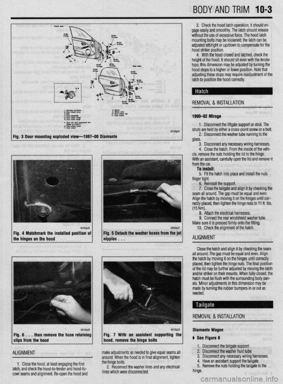
3. Check the hood latch operation; it should en-
gage easily and smoothly. The latch should release
without the use of excessive force. The hood latch
mounting bolts may be loosened; the latch can be
adjusted left/right or up/down to compensate for the
hood striker position.
4. With the hood closed and latched, check the
height of the hood. It should sit even with the fender
tops; this dimension may be adjusted by turning the
hood stops to a higher or lower position. Note that
adjusting these stops may require readjustment of the
latch to position the hood correctly.
REMOVAL &INSTALLATION
1999-92 Mirage
1. Disconnect the liftgate support or strut. The
9315Ql10 struts are held by either a cross-point screw or a bolt.
2. Disconnect the washer tube running to the
glass.
3. Disconnect any necessary wiring harnesses.
4. Close the hatch. From the inside of the vehi-
cle, remove the nuts holding the lid to the hinge.
With an assistant. carefullv ooen the lid and remove it
from the car. ’
To install:
5. Fit the hatch into place and install the nuts
finger tight.
6. Reinstall the support.
7. Close the tailgate and align it by checking the
seam all around. Thegap must be equal and even.
Align the hatch by moving it on the hinges until cor-
rectly placed, then tighten the hinge nuts to 11 ft. Ibs.
(15 Nm).
8. Attach the electrical harnesses.
9. Connect the rear windshield washer tube.
Make sure it is pressed firmly onto the fitting.
10. Check the alignment of the hatch.
ALIGNMENT
Close the hatch and align it by checking the seam
all around. The gap must be equal and even. Align
the hatch by moving it on the hinges until correctly
placed, then tighten the hinge nuts. The final position
of the lid may be further adjusted by moving the latch
and/or striker on their mounts. When fully closed, the
hatch must be flush with the surrounding body pan-
els. Minor adjustments in this dimension may be
made by turning the rubber bumpers in or out as
needed.
REMOVAL &INSTALLATION
then remove the hose retaining
ALIGNMENT
1, Close the hood, at least engaging the first
latch, and check the hood-to-fender and hood-to-
cowl seams and alignment. Re-open the hood and Fig. 7 With an assistant supporting the
make adjustments as needed to give equal seams all
around. When the hood is in final alignment, tighten
the hinge bolts.
2. Reconnect the washer lines and any electrical
lines which were disconnected. Diamante Wagon
ti See Figure 8
1. Disconnect the tailgate support.
2. Disconnect the washer fluid tube.
3. Disconnect any necessary wiring harnesses.
4. Have an assistant support the tailgate.
5. Remove the nuts holding the tailgate to the
hinge.
Page 375 of 408

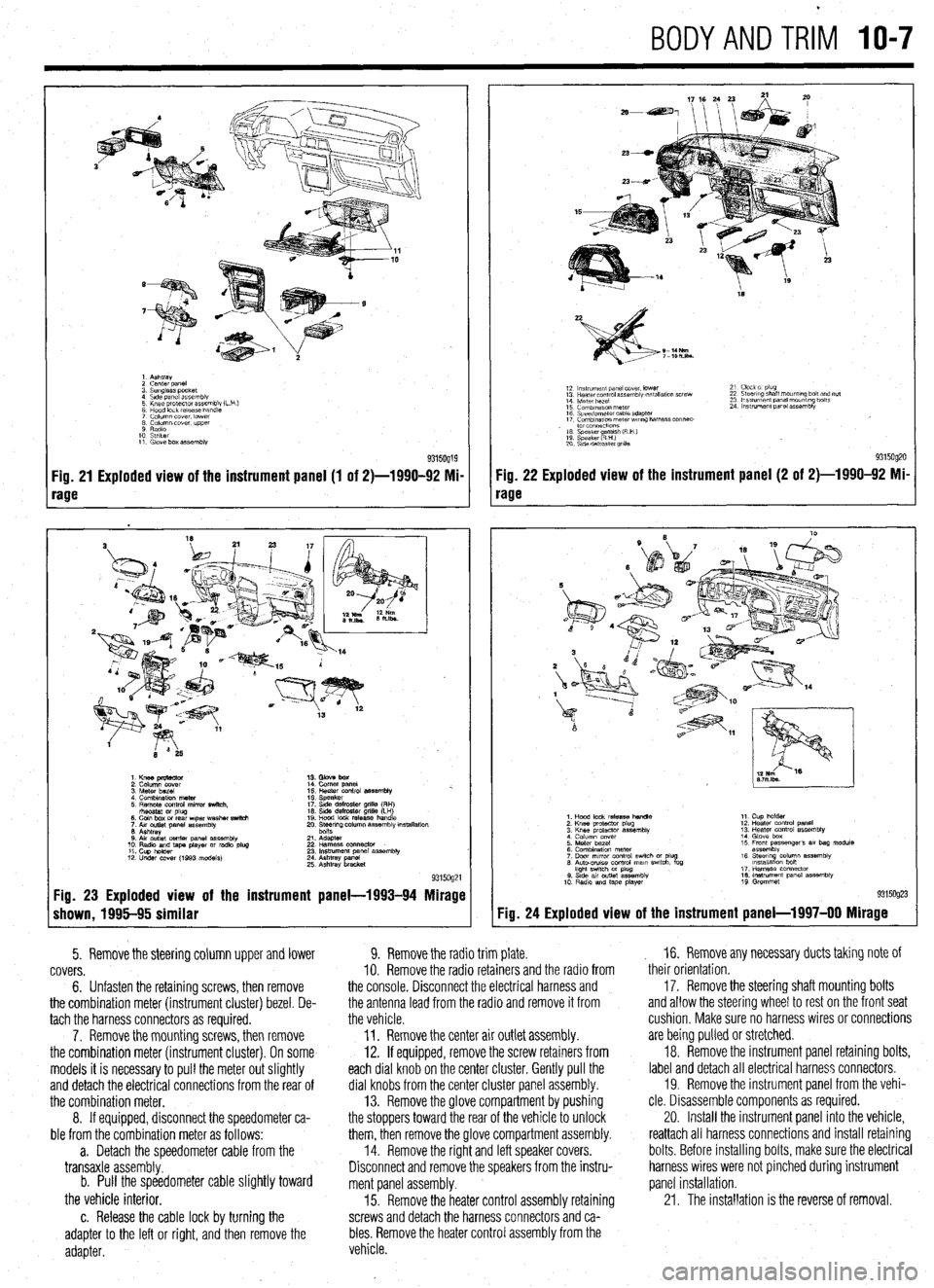
BODYANDTRIM IO-7
1. Ashtray
2 cenrer DaneI
3. Sunglass pocket
4 Side panel assembly
5 Knee protector assembly (L
6 Hood lock release handle
7 Column cover. lower
8 Column cover. upper
9 Radio
10 Striker
11. Glove box assembly
Fig. 21 Exploded view of the instrument panel (1 of 2)-1990-92 Mi-
rage
1. Knee pmtector
2. Column cover
3. Meter bezel
4. Combination meter
5. Remote control mirror switch.
rhsostat or plug
6. Coin box or rear wper washer switch
7. Aw outlet panel assembly
6. Ashtray
0. Air outlet center panel assembly
10. Radio and tape player or radio plug
11. Cup holder
12. Under COW (1993 models) 14. Comer panel
15. Heater control assembly %.
16. Speaker
17. Side defroster grille (RH)
16. Side defroster grille (LH)
19. Hood lock release handle
20. Ee$ng column assembly mstallation
21. Adapter
22 Harness oonnector
23. Instrument panel assembly
24. Ashtray panel
25. Ashtray bracket
9315og21 Fig. 23 Exploded view of the instrument panel-1993-94 Mirage
shown, 1995-95 similar
5. Remove the steering column upper and lower
covers.
6. Unfasten the retaining screws, then remove
the combination meter (instrument cluster) bezel. De-
tach the harness connectors as required.
7. Remove the mounting screws, then remove
the combination meter (instrument cluster). On some
models it is necessary to pull the meter out slightly
and detach the electrical connections from the rear of
the combination meter.
8. If equipped, disconnect the speedometer ca-
ble from the combination meter as follows:
a. Detach the speedometer cable from the
transaxle assembly.
b. Pull the speedometer cable slightly toward
the vehicle interior.
c. Release the cable lock by turning the
adapter to the left or right, and then remove the
adapter.
18
S-14Nm
7-lOh.lbs.
12 ln~v~rnent panel cover. lower
13 Hearer control assembly w,tallatlon screw
14 Meter bezel
15 Combination meter
16 Speedometer cable adapter
17 Comblnawn meterwr~ng harness connec-
. to1 co”“ectlo”s
16 Speaker amlsh (R H )
19 Speaker RHI e
20 S\de defroster grllla 21 Clock 01 plug
22 Steering shaft mount,ng bolt and nut
23 Ins!rument panel mounting bolts
24 Instrument panel assembly
9315og20 Fig. 22 Exploded view of the instrument panel (2 of 2)-1990-92 Mi-
rage
Fig. 24
1. Hood lock release handle
2. Knee protactor plug
3. Knee protector assembly
4 Column cover
5. Meter bezel
6. Combination meter
7. Door mrror control swich or plug
6. Auto-CNISO control mam swtch. fog
hght swtch M plug
0. Stde av outlet assembly
10 Radio and tape player 11. Cup holder
12. Heater control panel
13. Heater control assembly
14. Glove box
15 Front passenger’s 81, bag module
assembly
16. Steerq column assembly
lnstallatlon bon
17. Harness connector
16. Instrument panel assembly
19 Grommet
Exploded view of the instrument panel-l 997-00 Mirage
9. Remove the radio trim plate.
IO. Remove the radio retainers and the radio from
the console. Disconnect the electrical harness and
the antenna lead from the radio and remove it from
the vehicle.
11. Remove the center air outlet assembly.
12. If equipped, remove the screw retainers from
each dial knob on the center cluster. Gently pull the
dial knobs from the center cluster panel assembly.
13. Remove the glove compartment by pushing
the stoppers toward the rear of the vehicle to unlock
them, then remove the glove compartment assembly.
14. Remove the right and left speaker covers.
Disconnect and remove the speakers from the instru-
ment panel assembly.
15. Remove the heater control assembly retaining
screws and detach the harness connectors and ca-
bles. Remove the heater control assembly from the
vehicle. , 16. Remove any necessary ducts taking note of
their orientation,
17. Remove the steering shaft mounting bolts
and allow the steering wheel to rest on the front seat
cushion, Make sure no harness wires or connections
are being pulled or stretched.
18. Remove the instrument panel retaining bolts,
label and detach all electrical harness connectors.
19. Remove the instrument panel from the vehi-
cle. Disassemble components as required.
20. Install the instrument panel into the vehicle,
reattach all harness connections and install retaining
bolts. Before installing bolts, make sure the electrical
harness wires were not pinched during instrument
panel installation.
21. The installation is the reverse of removal.
Page 376 of 408

IO-8 BODYANDTRIM
cFroni 1990 ma&Is>
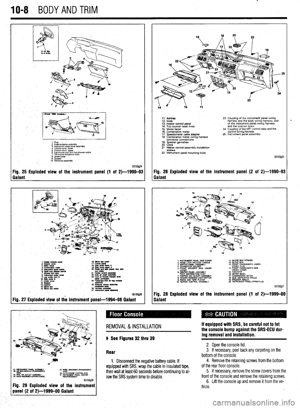
1 Plug
2 Knee pr&ctor assembb
3 lnsuumen~ under covet assembly
4. Column lxwer. lower :
5. Column cover upper
6 Lap shower duct and foot shcwai nozzle
7 Ttlt bracket installalm bolts
0 Undercover
9. stopper
10 Glove box assembly
93150@4 Fig. 25 Exploded view of the instrument panel (1 of 2)-1990-93 Fig. 26 Exploded view of the instrument panel (2 of 2)-1990-93
Galant Galant
1.CUllUCU+RC&pllU 16. Gbve bm eewr
i: iiiikz!!T 17. cucw gmnl
4. Cfnnbinuion meta 19. qds cww bww A
5 ‘~fiJzg%L L: ,“zr&, beat. md
21 L% sssemuy
8lmwmemu&cowr 236&1ou(W~
S.LapOdrduQB
10. slds cw4# B 23 ~u,~e-
11. LIdsI corn
::: s%ZZ
14. Gbw bx / ;:+q-=:-
kmasa
IS. Gkw ba SIiikw 2&HWSSCCl!ZL
2rtnsmlmuapr*lrvrnbly
@ma
Fig. 27 Exploded view of the instrument panel-1994-98 Galant
1;. p;;w
13: Heater control panel
14. Trip counter reset knob
15. Meter bezel
16. Combination meter
17. Speedometer cable adapter
18. Combrnatron meter wiring harness
connector connecttons
19. Speaker garnrshes
20. Clock 23. Coupling of the Instrument panel wiring
harness and the body wiring harness, and
of the Instrument panel wrring harness
and the junctlon block
24. Coupling of the MFI control relay and the
control wiring harness
25. Instrument panel assembly
21. Heater control assembly installation
9C?WS 22. Instrument panel mounting bolts
93150925
1. INSTRUMENT PANEL SIDE COVER
2. HOOD LOCK RELEASE HANDLE
3. SWITCH PANEL ASSEMBLY
4 CONNECTOR H+DER
5. ER DRIVERS SIDE UNDER
6. CENTER PANEL ASSEMBLY
FOOT MSTRISUTION DUCT
7. CENTER AIR OUTLET ASSEMBLY
8. HAZARO WARNING LIGHT SWfTCti
9. RADIO AN0 TAPE PLAYER
10. H!ZATER CONTROL ASSEMBLY 1,. GLOV2 BOX STRIKER
12. GLOVE SOX
13 FRONT PASSENGER’S UNOER
COVER PLUG
14. FRONT PASSENGER’S SIDE
UNDER COVER
15. RHEOSTAT
16. METER BEZEL
17. COMBINATION METER
18. SIDE DEFROSTER GRILLE
19 SPEAKER GRILLE
mo. INSTRUMENT PANEL UPPER PLUG
93159927
Fig. 28 Exploded view of the instrument panel (1 of 2)-1999-00
Galant
~~~~~~~~~
Fig. 29 Exploded view of the instrument
REMOVAL &INSTALLATION
) See Figures 32 thru 39 If equipped with SRS, be careful not to let
the console bump against the SRS-ECU dur-
ing removal and installation.
Rear 2. Open the console lid. 3. If necessary, peel back any carpeting on the
bottom of the console.
1. Disconnect the negative battery cable. If
equipped with SRS, wrap the cable in insulated tape,
then wait at least 60 seconds before continuing to al-
low the SRS system time to disable.
4. Remove the retaining screws from the bottom
of the rear floor console.
5. If necessary, remove the screw covers from the
front of the console and remove the retaining screws.
6. Lift the console up and remove it from the ve-
hicle.
rb
Page 377 of 408

c BODYANDTRi'l IO-9
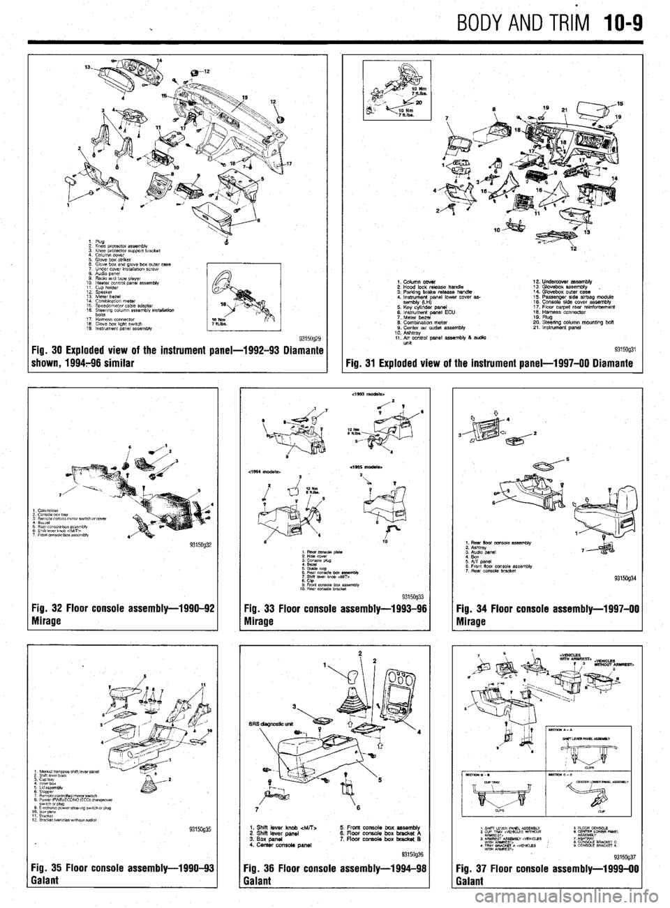
:: k% protector assembly
3. Knee protector support bracket
4. Column cover
5 Glove box striker
6 Glove box and glove box outer case
7 Under cover mstallatmn screw
8. Audio panel
9 Radio and tape player
10 Heater control panel
assembly 11 Cup holder
12. Speaker
13 Meter bezel
14 Combination meter
15 Speeoometer cable adapter
16 %&rrng column assembly rnstallatioh
17 Harness connector
18. Glove box kght swatch
19. Instrument panel assembly
9315og29 Fig. 30 Exploded view of the instrument panel-1992-93 Diamante
shown, 1994796 similar
I Cam holder
2 Console box tray
3 Remote control mrror swatch drcover
1 Berrel
3 Rear cms~ie box assembly
3 Shift lever knob 4vitT>
7 Front eonsale box assembly
Fig. 32 Floor console assembly-1990-92
Yg. 33 Floor console assembly-1993-96
Nlirage
Mirage
1 Manual tmnsaxle shrft lever panel 2 Shrft lever boat 3. cup tray 4 lnnerbdx
6 Lrd assembly
6 Stopper 7 Remote cO”trOned nl,rrorSwl,Ch 8 PowerlFVWECONO (EC01 changeover
12 Bracket Wvcles wrthout addlo)
Fig. 35 Floor console assembly-l 990-93
Galant
4’
2
ia
9315og31 Fig. 31
Exploded view of the instrument
panel-l 997-00 Diamante
1. Column cover
2. Hood lock release handle
3. Parking brake release handle
4. Instrument anal lower cover as-
sembly (LH
P 5. Key cylinder panel
6. instrument panel ECU
7. Meter bezel
0. Combination meter 9. Center air outlet assembly
10. Ashtray
11. Air control panel assembly 8 audio
unit 12. Undercover assembly
13. Glovebox assembly
14. Glovebox outer case
15. Passenger side airbag module
16. Console side cover assemblv
17. Flow carpet rear rainforcem&t
18. Harness connector
19. Plug
20. Steering column mountlng bolt
21. Instrument panel
6 Rear cmsole box es%mbly
7
Shrff lever knob
6. CtQ 9 Front console box assembfk
10. Rear console bracket 9315og33
7 6
1. Shii lever knob &ATT:.
2. Shi lever panel
3. Box panel
4. Center console panel 5. Front console box assembly
6. Floor console box bracket A
7. floar console box bradret B
Fig. 36 Floor console assembly-1994-98
Galant
1. Rear floor console assembly
2. Ashtray
6. Front floor console assembly
7 Rear console bracket
Fig. 34 Floor console assembly-1997-00
Mirage
Fig. 37 Floor console assembly-l 999-00
Galant