2024 GMC SIERRA DENALI parking brake
[x] Cancel search: parking brakePage 341 of 440
GMC Sierra/Sierra Denali 2500 HD/3500 HD Owner Manual (GMNA-
Localizing-U.S./Canada-16908340) - 2024 - CRC - 12/7/22
Vehicle Care 339
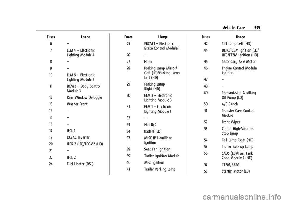
FusesUsage
6 –
7 ELM 4 –Electronic
Lighting Module 4
8 –
9 –
10 ELM 6 –Electronic
Lighting Module 6
11 BCM 3 –Body Control
Module 3
12 Rear Window Defogger
13 Washer Front
14 –
15 –
16 –
17 IECL 1
19 DC/AC Inverter
20 IECR 2 (LD)/EBCM2 (HD) 21 –
22 IECL 2
24 Fuel Heater (DSL) Fuses
Usage
25 EBCM 1 –Electronic
Brake Control Module 1
26 –
27 Horn
28 Parking Lamp Mirror/ Grill (LD)/Parking Lamp
Left (HD)
29 Parking Lamp Right (HD)
30 ELM 3 –Electronic
Lighting Module 3
31 ELM 1 –Electronic
Lighting Module 1
32 –
33 Not R/C
34 Radars (LD) 37 MISC IP Headliner Ignition
38 Seat Fan Ignition
39 Trailer Ignition Module
40 Misc Ignition 41 Trailer Parking Lamp Fuses
Usage
42 Tail Lamp Left (HD)
44 DEFC/ICCM Ignition (LD/ HD)/FTZM Ignition (HD)
45 Secondary Axle Motor
46 Engine Control Module Ignition
47 –
48 –
49 Transmission Auxiliary Oil Pump (LD)
50 A/C Clutch 51 Transfer Case Control Module
52 Front Wiper
53 Center High-Mounted Stop Lamp
54 Tail Lamp Right (HD) 55 Trailer Back-up Lamp
56 SADS (LD)/Fuel Tank Zone Module 2 (HD)
57 TTPM/SBZA
58 Starter Motor (LD)
Page 342 of 440

GMC Sierra/Sierra Denali 2500 HD/3500 HD Owner Manual (GMNA-
Localizing-U.S./Canada-16908340) - 2024 - CRC - 12/7/22
340 Vehicle Care
FusesUsage
60 Powertrain Sensor 2 (DSL)
61 Active Hydraulic Steering (HD)
62 DEFC Batt 1/CVS
63 Trailer Brake
65 –
66 Cooling Fan Motor Left (LD)
67 –
68 DEFC Batt 2
69 Starter Pinion (LD Gas)/ Starter Motor (HD)
71 Cooling Fan Lower (LD)
72 Cooling Fan Right (LD)
73 Trailer Stop/Turn Lamp Left
74 Trailer Interface Module 2
75 Integrated Chassis Control Module
76 Electric RNG BDS Fuses
Usage
78 Engine Control Module
79 Cabin Cool Pump 17W (LD)/Auxiliary
Battery (HD)
80 Powertrain Sensor 1 (DSL)
81 Trailer Stop/Turn Lamp Right
82 Trailer Interface Module 1
83 FTZM 1
84 Trailer Battery 85 –
86 Engine Control Module 87 Injector B Even
88 O2 B Sensor
89 O2 A Sensor
90 Injector A Odd 91 Engine Control Module Throttle Control (HD) Fuses
Usage
92 Cool Fan Clutch (HD DSL)/Aeroshutter
(LD/HD)
Relays Usage
5 Rear Window Defogger
18 DC/AC Inverter
23 Fuel Heater (DSL)
35 Parking Lamp
36 Run/Crank
43 Secondary Axle Motor
59 A/C Clutch
64 Starter Motor (LD)/Cool Fan Clutch (HD DSL)
70 Starter Pinion (LD Gas)/ Starter Motor (HD)
77 Powertrain
Page 355 of 440

GMC Sierra/Sierra Denali 2500 HD/3500 HD Owner Manual (GMNA-
Localizing-U.S./Canada-16908340) - 2024 - CRC - 12/7/22
Vehicle Care 353
.The TPMS sensor matching process was
not done or not completed successfully
after rotating the tires. The malfunction
light and the DIC message should go off
after successfully completing the sensor
matching process. See "TPMS Sensor
Matching Process" later in this section.
.One or more TPMS sensors are missing or
damaged. The malfunction light and the
DIC message should go off when the
TPMS sensors are installed and the sensor
matching process is performed
successfully. See your dealer for service.
.Replacement tires or wheels do not match
the original equipment tires or wheels.
Tires and wheels other than those
recommended could prevent the TPMS
from functioning properly. SeeBuying
New Tires 0360.
.Operating electronic devices or being near
facilities using radio wave frequencies
similar to the TPMS could cause the TPMS
sensors to malfunction.
If the TPMS is not functioning properly, it
cannot detect or signal a low tire pressure
condition. See your dealer for service if the
TPMS malfunction light and DIC message
come on and stay on.
Tire Fill Alert (If Equipped)
This feature provides visual and audible
alerts outside the vehicle to help when
inflating an underinflated tire to the
recommended cold tire pressure.
When the low tire pressure warning light
comes on: 1. Park the vehicle in a safe, level place.
2. Set the parking brake firmly.
3. Place the vehicle in P (Park).
4. Add air to the tire that is underinflated. The turn signal lamp will flash.
When the recommended pressure is
reached, the horn sounds once and the
turn signal lamp will stop flashing and
briefly turn solid.
Repeat these steps for all underinflated tires
that have illuminated the low tire pressure
warning light.
{Warning
Overinflating a tire could cause the tire
to rupture and you or others could be
injured. Do not exceed the maximum (Continued)
Warning (Continued)
pressure listed on the tire sidewall. See
Tire Sidewall Labeling0346 and
Vehicle Load Limits 0210.
If the tire is overinflated by more than
35 kPa (5 psi), the horn will sound multiple
times and the turn signal lamp will continue
to flash for several seconds after filling
stops. To release and correct the pressure,
while the turn signal lamp is still flashing,
briefly press the center of the valve stem.
When the recommended pressure is reached,
the horn sounds once.
If the turn signal lamp does not flash within
15 seconds after starting to inflate the tire,
the tire fill alert has not been activated or is
not working.
If the hazard warning flashers are on, the
tire fill alert visual feedback will not work
properly.
The TPMS will not activate the tire fill alert
properly under the following conditions:
.There is interference from an external
device or transmitter.
.The air pressure from the inflation device
is not sufficient to inflate the tire.
Page 356 of 440

GMC Sierra/Sierra Denali 2500 HD/3500 HD Owner Manual (GMNA-
Localizing-U.S./Canada-16908340) - 2024 - CRC - 12/7/22
354 Vehicle Care
.There is a malfunction in the TPMS.
.There is a malfunction in the horn or turn
signal lamps.
.The TPMS sensor identification code is not
registered to the system.
.The TPMS sensor battery is low.
If the tire fill alert does not operate due to
TPMS interference, move the vehicle about
1 m (3 ft) back or forward and try again.
If the tire fill alert feature is not working,
use a tire pressure gauge.
TPMS Sensor Matching Process
Use this TPMS Sensor Matching Process if
your vehicle is equipped with dual rear
wheels:
Each TPMS sensor has a unique
identification code. The identification code
needs to be matched to a new tire/wheel
position after rotating the vehicle’s tires or
replacing one or more of the TPMS sensors.
Also, the TPMS sensor matching process
should be performed after replacing a spare
tire with a road tire containing the TPMS
sensor. The malfunction light and the DIC
message should go off at the next ignition
cycle. The sensors are matched to the tire/
wheel positions, using a TPMS relearn tool,
in the following order: driver side front tire, passenger side front tire, passenger side
outer rear tire, passenger side inner rear
tire, driver side outer rear tire, and driver
side inner rear tire. See your dealer for
service or to purchase a relearn tool.
A TPMS relearn tool can also be purchased.
See Tire Pressure Monitor Sensor Activation
Tool at www.gmtoolsandequipment.com or
call 1-800-GM TOOLS (1-800-468-6657).
There are two minutes to match the first
tire/wheel position, and five minutes overall
to match all six tire/wheel positions. If it
takes longer, the matching process stops
and must be restarted.
The TPMS sensor matching process is:
1. Set the parking brake.
2. Turn the ignition on without starting the vehicle.
3. Uplevel DIC Only: Make sure the Tire Pressure info page option is turned on.
The info pages on the DIC can be turned
on and off through the Options menu.
See Driver Information Center (DIC) (Base
Level) 0131 or
Driver Information Center (DIC) (Uplevel)
0 133. 4. If the vehicle has an uplevel DIC, use the
DIC controls on the right side of the
steering wheel to scroll to the Tire
Pressure screen under the DIC info page.
If the vehicle has a base level DIC, use
the trip odometer reset stem to scroll to
the Tire Pressure screen.
5. If the vehicle has an uplevel DIC, press and hold the thumbwheel located in the
center of the DIC controls on the right
side of the steering wheel.
If the vehicle has a base level DIC, press
and hold the trip odometer reset stem
for about five seconds. A message asking
if the process should begin should
appear. Select yes and press the trip
odometer reset stem to confirm the
selection.
The horn sounds twice to signal the
receiver is in relearn mode and the TIRE
LEARNING ACTIVE message displays on
the DIC screen.
6. Start with the driver side front tire.
7. Place the relearn tool against the tire sidewall, near the valve stem. Then press
the button to activate the TPMS sensor.
A horn chirp confirms that the sensor
identification code has been matched to
this tire and wheel position.
Page 367 of 440
GMC Sierra/Sierra Denali 2500 HD/3500 HD Owner Manual (GMNA-
Localizing-U.S./Canada-16908340) - 2024 - CRC - 12/7/22
Vehicle Care 365
If a tire goes flat, avoid further tire and
wheel damage by driving slowly to a level
place, well off the road, if possible. Turn on
the hazard warning flashers. SeeHazard
Warning Flashers 0146.
If your vehicle is loaded at or near
maximum cargo capacity, it may be difficult
to fit the jack under the vehicle due to the
environment (shoulder slope, road debris,
etc.). Removal of some weight may improve
the ability to fit the jack under the vehicle
at the correct jacking location.
{Warning
Changing a tire can be dangerous. The
vehicle can slip off the jack and roll over
or fall causing injury or death. Find a
level place to change the tire. To help
prevent the vehicle from moving:
1. Set the parking brake firmly.
2. Shift the vehicle to P (Park).
3. For vehicles with four-wheel drive with an N (Neutral) transfer case
position, be sure the transfer case is
in a drive gear —not in N (Neutral).
(Continued)
Warning (Continued)
4. Turn off the engine and do notrestart while the vehicle is raised.
5. Do not allow passengers to remain in the vehicle.
6. Place wheel blocks, if equipped, on both sides of the tire at the opposite
corner of the tire being changed.
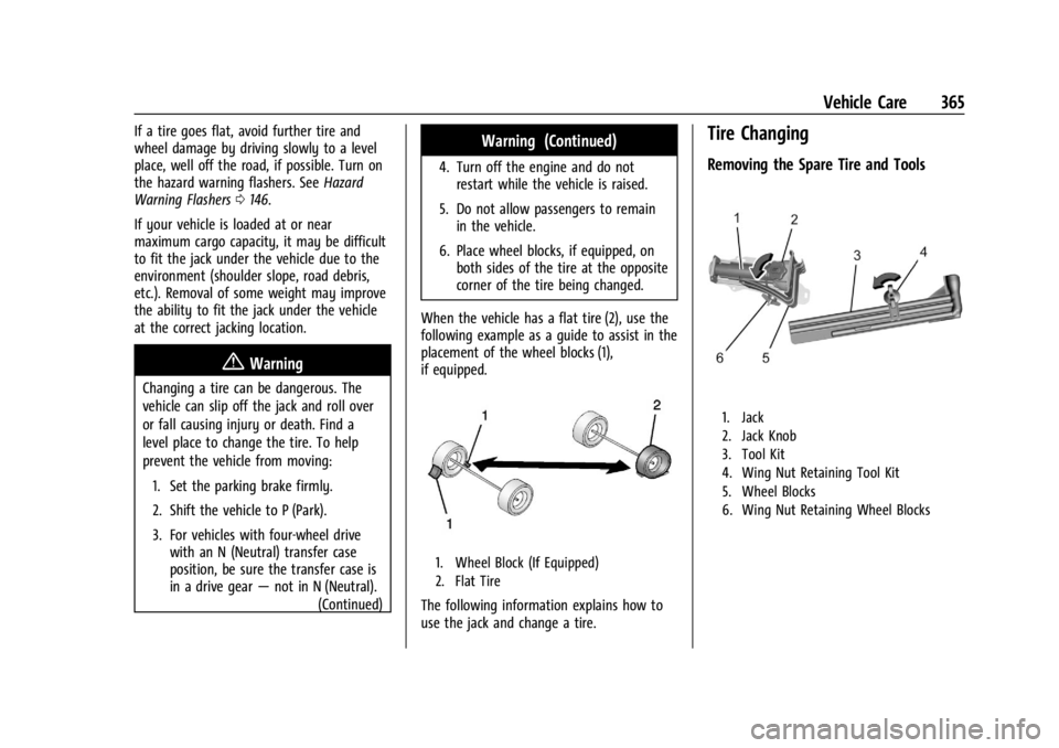
When the vehicle has a flat tire (2), use the
following example as a guide to assist in the
placement of the wheel blocks (1),
if equipped.
1. Wheel Block (If Equipped)
2. Flat Tire
The following information explains how to
use the jack and change a tire.
Tire Changing
Removing the Spare Tire and Tools
1. Jack
2. Jack Knob
3. Tool Kit
4. Wing Nut Retaining Tool Kit
5. Wheel Blocks
6. Wing Nut Retaining Wheel Blocks
Page 379 of 440
GMC Sierra/Sierra Denali 2500 HD/3500 HD Owner Manual (GMNA-
Localizing-U.S./Canada-16908340) - 2024 - CRC - 12/7/22
Vehicle Care 377
Caution (Continued)
by the vehicle warranty. Always connect
and remove the jumper cables in the
correct order, making sure that the cables
do not touch each other or other metal.
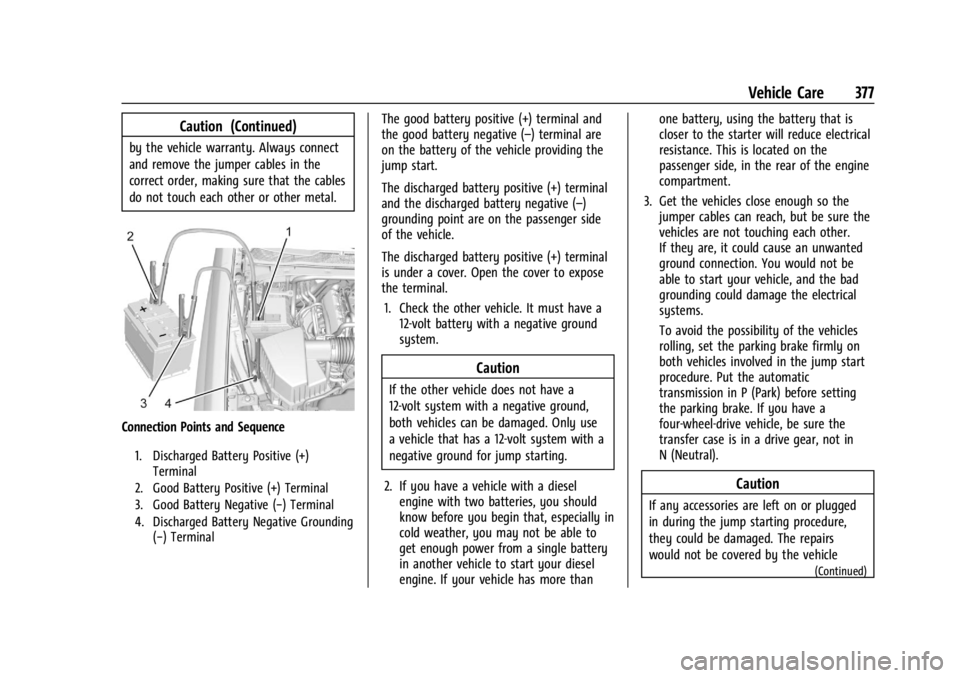
Connection Points and Sequence
1. Discharged Battery Positive (+)Terminal
2. Good Battery Positive (+) Terminal
3. Good Battery Negative (−) Terminal
4. Discharged Battery Negative Grounding (−) Terminal
The good battery positive (+) terminal and
the good battery negative (–) terminal are
on the battery of the vehicle providing the
jump start.
The discharged battery positive (+) terminal
and the discharged battery negative (–)
grounding point are on the passenger side
of the vehicle.
The discharged battery positive (+) terminal
is under a cover. Open the cover to expose
the terminal.
1. Check the other vehicle. It must have a 12-volt battery with a negative ground
system.
Caution
If the other vehicle does not have a
12-volt system with a negative ground,
both vehicles can be damaged. Only use
a vehicle that has a 12-volt system with a
negative ground for jump starting.
2. If you have a vehicle with a diesel engine with two batteries, you should
know before you begin that, especially in
cold weather, you may not be able to
get enough power from a single battery
in another vehicle to start your diesel
engine. If your vehicle has more than one battery, using the battery that is
closer to the starter will reduce electrical
resistance. This is located on the
passenger side, in the rear of the engine
compartment.
3. Get the vehicles close enough so the jumper cables can reach, but be sure the
vehicles are not touching each other.
If they are, it could cause an unwanted
ground connection. You would not be
able to start your vehicle, and the bad
grounding could damage the electrical
systems.
To avoid the possibility of the vehicles
rolling, set the parking brake firmly on
both vehicles involved in the jump start
procedure. Put the automatic
transmission in P (Park) before setting
the parking brake. If you have a
four-wheel-drive vehicle, be sure the
transfer case is in a drive gear, not in
N (Neutral).
Caution
If any accessories are left on or plugged
in during the jump starting procedure,
they could be damaged. The repairs
would not be covered by the vehicle
(Continued)
Page 381 of 440
GMC Sierra/Sierra Denali 2500 HD/3500 HD Owner Manual (GMNA-
Localizing-U.S./Canada-16908340) - 2024 - CRC - 12/7/22
Vehicle Care 379
11. Start the vehicle with the good batteryand run the engine for a while.
12. Try to start the vehicle that had the dead battery. If it will not start after a
few tries, it probably needs service.
Jumper Cable Removal
Reverse the sequence exactly when
removing the jumper cables.
After starting the disabled vehicle and
removing the jumper cables, allow it to idle
for several minutes.
Towing the Vehicle
Transporting a Disabled Vehicle
Caution
Incorrectly transporting a disabled vehicle
may cause damage to the vehicle. Use
proper tire straps to secure the vehicle to
the flatbed tow truck. Do not strap or
hook to any frame, underbody,
or suspension component not specified
below. Do not move vehicles with drive
axle tires on the ground. Damage is not
covered by the vehicle warranty.
Caution
The vehicle may be equipped with an
electric parking brake and/or a
mechanical transmission range select
shifter. In the event of a loss of 12-volt
battery power, the electric parking brake
cannot be released, and the vehicle
cannot be shifted to N (Neutral). Tire
skates or dollies must be used under the
non-rolling tires to prevent damage while
loading/unloading the vehicle. Dragging
the vehicle will cause damage not
covered by the vehicle warranty.
Caution
The vehicle may be equipped with a tow
eye. Improper use of the tow eye may
cause damage to the vehicle and is not
covered by the vehicle warranty.
If equipped, use the tow eye to load the
vehicle onto a flatbed tow truck from a
flat road surface, or to move the vehicle
a very short distance at a walking pace.
The tow eye is not designed for off-road
(Continued)
Caution (Continued)
recovery. The vehicle must be in
N (Neutral) with the electric parking
brake released when using the tow eye.
Contact a professional towing service if the
disabled vehicle must be transported. GM
recommends a flatbed tow truck to
transport a disabled vehicle. Use ramps to
help reduce approach angles, if necessary.
If equipped, a tow eye may be located near
the spare tire or emergency jack. Do not use
the tow eye to pull the vehicle from the
snow, mud, sand, or ditch. Tow eye threads
may have right or left-hand threads. Use
caution when installing or removing the
tow eye.
The vehicle must be in N (Neutral) and the
electric parking brake must be released
when loading the vehicle onto a flatbed tow
truck.
.If the 12-volt battery is dead and/or
electric parking brake is not released, the
vehicle will not move. Try to jump start
the vehicle with a known good 12-volt
battery, shift the car into N (Neutral), and
release the electric parking brake. Refer to
Jump Starting - North America 0376.
Page 383 of 440
GMC Sierra/Sierra Denali 2500 HD/3500 HD Owner Manual (GMNA-
Localizing-U.S./Canada-16908340) - 2024 - CRC - 12/7/22
Vehicle Care 381
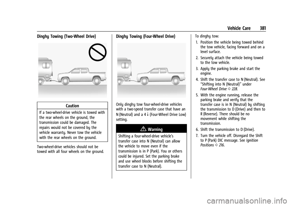
Dinghy Towing (Two-Wheel Drive)
Caution
If a two-wheel-drive vehicle is towed with
the rear wheels on the ground, the
transmission could be damaged. The
repairs would not be covered by the
vehicle warranty. Never tow the vehicle
with the rear wheels on the ground.
Two-wheel-drive vehicles should not be
towed with all four wheels on the ground.
Dinghy Towing (Four-Wheel Drive)
Only dinghy tow four-wheel-drive vehicles
with a two-speed transfer case that have an
N (Neutral) and a 4
n(Four-Wheel Drive Low)
setting.
{Warning
Shifting a four-wheel-drive vehicle's
transfer case into N (Neutral) can allow
the vehicle to move even if the
transmission is in P (Park). You or others
could be injured. Set the parking brake
and use wheel blocks before shifting the
transfer case to N (Neutral). To dinghy tow:
1. Position the vehicle being towed behind the tow vehicle, facing forward and on a
level surface.
2. Securely attach the vehicle being towed to the tow vehicle.
3. Apply the parking brake and start the engine.
4. Shift the transfer case to N (Neutral). See “Shifting into N (Neutral)” under
Four-Wheel Drive 0228.
5. With the engine running, release the parking brake and verify that the
transfer case is in N (Neutral) by shifting
the transmission to D (Drive) and then to
R (Reverse). There should be no
movement while shifting the
transmission.
6. Shift the transmission to D (Drive).
7. Turn the vehicle off. Disregard the Shift to P (Park) DIC message. See Ignition
Positions 0216.