2024 FORD F650/750 air condition
[x] Cancel search: air conditionPage 217 of 386
VEHICLE INSPECTION
INFORMATION
To make sure your vehicle is ready tooperate, conduct a pre-trip inspection atthe beginning of each work period. Followthe steps listed in this section to verify aproper vehicle inspection procedure.
WARNING: Exercise great cautionwhen working on a vehicle equipped withan automatic fan clutch. The fan startsin motion only after the engine coolantreaches a predetermined temperatureor the refrigerant pressure (if equippedwith air conditioning) reaches apredetermined setting. The fan starts atthis point with no advance warning.Never reach near, or permit objects toprotrude into, the fan blade radius whilethe engine is running as this could resultin vehicle damage, personal injury ordeath.
WARNING: Do not operate thevehicle if any suspension conditionslisted in the following charts are evident.Loss of steering or suspension couldresult in property damage, personal injuryor death.
WARNING: If a wheel must bechanged, obtain expert tire service help.Mounting and un-mounting of tiresshould only be performed by a qualifiedtechnician using necessary safetyprocedures and equipment, otherwisethe result could be property damage,personal injury or death.
Note:Always make sure you apply theparking brake before starting the engine.
Engine compartment (with engine off)
Use the dipstick to verify the oil level is in the proper operatingrange. See Engine Oil Dipstick (page 227).Engine oil
Look through the plastic reservoir and verify the coolant levelis within the proper operating range. Do not remove thepressure cap until the coolant has cooled. See EngineCoolant Check (page 238).
Engine coolant
Verify that the fluid level is in the proper operating range. SeePower Steering Fluid Check (page 246).Power steering fluid
Remove the master cylinder caps and inspect the fluid level.See Brake Fluid Check (page 245).Brake fluid
213
2024 F-650/750 (TBC) , enUSA, Edition date: 202210, First-PrintingVehicle Inspection Guide
Page 218 of 386
Engine compartment (with engine off)
Inspect for glazing, fraying or cracking. There should be nomore than 5-7 cracks per rib, per 1 in (2.5 cm)Belts (fan, alternator,water pump and airconditioningcompressor)
Inspect for signs of fluid puddles or dripping fluid on theground under the engine, or the underside of the engine.Fluid leaks
Inspect for debris that may have collected on the HVAC airinlet grille or inside the exterior module as this may reducesystem performance.
HVAC air inlet
Engine starting (with parking brake applied)
Before entering the cab, verify that the vehicle is equippedwith spare electrical fuses (if used), three red reflectivetriangles, a properly charged and rated fire extinguisher andwheel chocks.
Safety and emergencyequipment
Walk around the vehicle and verify all steps and grab handles,inside and out (as well as behind), are tight and clean. Useextreme caution and a three-point stance at all times.
Inspect door latches for proper closing, latching and locking.
Set the parking brake. Make sure the gearshift lever is inneutral (N) or park (P) (if equipped with a park position).Starting the engine
Diesel engine: Turn the key to the on position. Turn the keyto start when the wait to start indicator light in the instrumentcluster turns off.
Gasoline engine: Turn the key to start, and then release itas soon as the engine starts.
Verify pressure builds to normal operating range.Engine oil pressure
A tone indicating low air pressure should sound immediatelyafter the engine starts but before the compressor has built-up pressure. The tone should stop when the air pressurereaches 70 psi (483 kPa). Let the air pressure build togoverned cutout pressure, which should occur between115–130 psi (793–896 kPa).
Low air pressure warningtone (if equipped with anair compressor)
Press the accelerator and verify that it operates smoothly,without any binding or irregular feel. Release the pedal andverify the engine returns to idle speed immediately.
Accelerator
214
2024 F-650/750 (TBC) , enUSA, Edition date: 202210, First-PrintingVehicle Inspection Guide
Page 224 of 386
Rear brakes
Inspect for cracked, worn or frayed hoses, and that all coup-lings are secure.Hoses
Verify that there are no cracks or dents, and that the cham-bers are securely mounted.Brake chambers
Inspect for broken, loose or missing parts.Slack adjusters
Note: The angle between the push rod and adjuster armshould be approximately 90 degrees when the brakes areapplied. When pulled by hand, the push rod should not movemore than approximately 1 in (2.5 cm).
Verify that there are no cracks, dents, holes, and no loose ormissing bolts and that the brake linings are not worn,dangerously thin or contaminated by lubricant.
Drums
Rear wheels
Check for even separation of dual wheels, and that the tiresare not touching each other.Spacers
Inspect for damaged or bent rims. They should not havewelding repairs, and there should be no rust trails, whichindicate it is loose on the wheel.
Rims
Verify all lug nuts are present and not loose (look for rusttrails around the lug nuts). There should be no cracks radiatingfrom the lug bolt holes or distortion of the bolt holes.
Lug nuts
Trailer
If you are pulling a trailer, perform aninspection of the trailer similar to that ofthe tractor. The inspection should followtrailer manufacturer recommendationsand should include at a minimum: generalcondition, landing gear, doors, sides, lights,reflectors, suspension, brakes, tires,wheels, cargo placement, stability andtie-downs.
Transmission
WARNING: If the unit starts in gearand/or the neutral start switch is notfunctioning correctly, the vehicle mayinadvertently move which could resultin property damage, personal injury ordeath.
Regularly inspect the transmission'sneutral start switch. The engine shouldonly start in neutral (N) or park (P) (ifequipped with a park position).
220
2024 F-650/750 (TBC) , enUSA, Edition date: 202210, First-PrintingVehicle Inspection Guide
Page 234 of 386
Action and DescriptionMessage
Oil Life: 100%
When the oil change indic-ator resets, the instrumentcluster displays 100%.
Repeat the process if the oilchange indicator does notreset.
CHANGING THE ENGINE AIR
FILTER - 6.7L DIESEL
Air Filter Restriction Gauge
WARNING: To reduce the risk ofvehicle damage and personal burninjuries, do not start your engine with theair cleaner removed and do not removeit while the engine is running.
Note:Operating your vehicle in heavysnowfall or extreme rain conditions mayallow excessive amounts of snow or waterinto the air intake system. This could plugor soak the air filter and cause the engine tolose power or shut down.
The restriction gauge, on the upper housingof the air filter assembly, measures thevacuum inside the air filter. The more theair filter is dirty or clogged, the higher thevacuum reading.
Check the air filter restriction gaugewhenever you open the hood to performgeneral engine maintenance or at leastevery 7,500 mi (12,000 km). If you operateyour vehicle in extremely dusty conditions,check and reset the gauge at least every500 mi (800 km), or two weeks, whichevercomes first. Change the air filter when therestriction gauge reads near the changefilter line and the gauge is yellow. If youallow the restriction gauge to reachmaximum restriction, you can affect yourengine performance and fuel economy.
Note:Do not blow out the air filter elementwith compressed air since the compressedair could damage the filter paper.
Note:Do not rely on filter appearancealone. A filter which appears to be dirty mayhave several thousand miles (kilometers)of life remaining.
After installation of the new filter element,reset the gauge by pressing the resetbutton on top of the gauge.
230
2024 F-650/750 (TBC) , enUSA, Edition date: 202210, First-PrintingMaintenanceE163372 E163373
Page 236 of 386
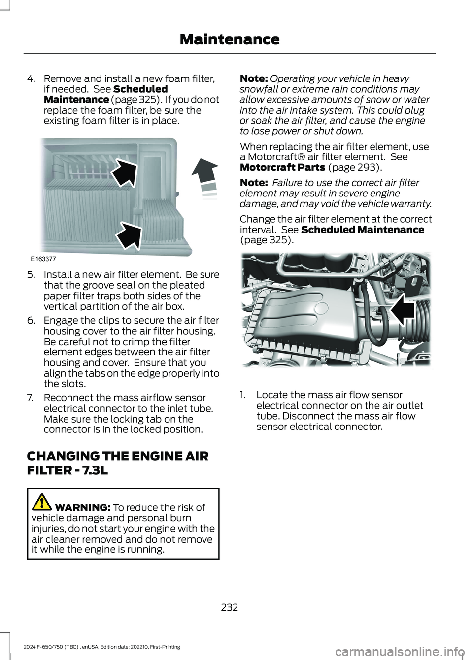
4.Remove and install a new foam filter,if needed. See ScheduledMaintenance (page 325). If you do notreplace the foam filter, be sure theexisting foam filter is in place.
5.Install a new air filter element. Be surethat the groove seal on the pleatedpaper filter traps both sides of thevertical partition of the air box.
6.Engage the clips to secure the air filterhousing cover to the air filter housing.Be careful not to crimp the filterelement edges between the air filterhousing and cover. Ensure that youalign the tabs on the edge properly intothe slots.
7.Reconnect the mass airflow sensorelectrical connector to the inlet tube.Make sure the locking tab on theconnector is in the locked position.
CHANGING THE ENGINE AIR
FILTER - 7.3L
WARNING: To reduce the risk ofvehicle damage and personal burninjuries, do not start your engine with theair cleaner removed and do not removeit while the engine is running.
Note:Operating your vehicle in heavysnowfall or extreme rain conditions mayallow excessive amounts of snow or waterinto the air intake system. This could plugor soak the air filter, and cause the engineto lose power or shut down.
When replacing the air filter element, usea Motorcraft® air filter element. SeeMotorcraft Parts (page 293).
Note: Failure to use the correct air filterelement may result in severe enginedamage, and may void the vehicle warranty.
Change the air filter element at the correctinterval. See Scheduled Maintenance(page 325).
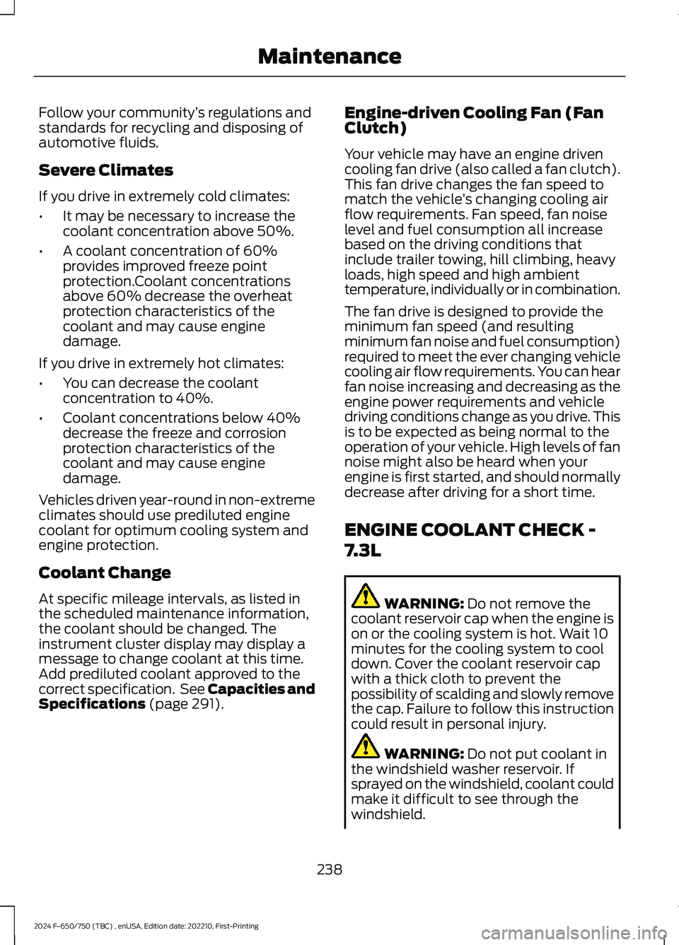
1.Locate the mass air flow sensorelectrical connector on the air outlettube. Disconnect the mass air flowsensor electrical connector.
232
2024 F-650/750 (TBC) , enUSA, Edition date: 202210, First-PrintingMaintenanceE163377 E317615
Page 238 of 386
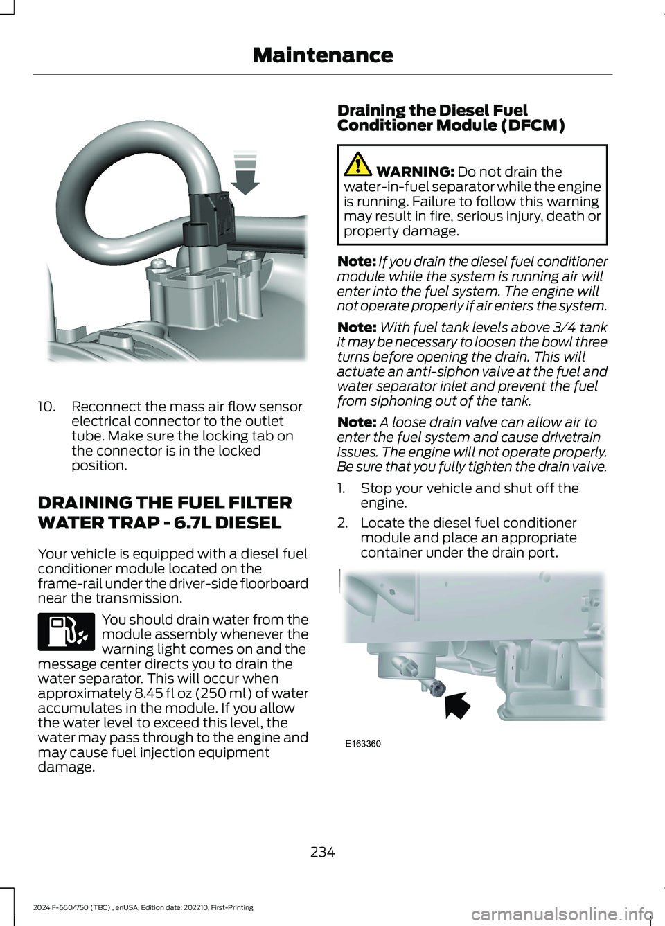
10.Reconnect the mass air flow sensorelectrical connector to the outlettube. Make sure the locking tab onthe connector is in the lockedposition.
DRAINING THE FUEL FILTER
WATER TRAP - 6.7L DIESEL
Your vehicle is equipped with a diesel fuelconditioner module located on theframe-rail under the driver-side floorboardnear the transmission.
You should drain water from themodule assembly whenever thewarning light comes on and themessage center directs you to drain thewater separator. This will occur whenapproximately 8.45 fl oz (250 ml) of wateraccumulates in the module. If you allowthe water level to exceed this level, thewater may pass through to the engine andmay cause fuel injection equipmentdamage.
Draining the Diesel FuelConditioner Module (DFCM)
WARNING: Do not drain thewater-in-fuel separator while the engineis running. Failure to follow this warningmay result in fire, serious injury, death orproperty damage.
Note:If you drain the diesel fuel conditionermodule while the system is running air willenter into the fuel system. The engine willnot operate properly if air enters the system.
Note:With fuel tank levels above 3⁄4 tankit may be necessary to loosen the bowl threeturns before opening the drain. This willactuate an anti-siphon valve at the fuel andwater separator inlet and prevent the fuelfrom siphoning out of the tank.
Note:A loose drain valve can allow air toenter the fuel system and cause drivetrainissues. The engine will not operate properly.Be sure that you fully tighten the drain valve.
1.Stop your vehicle and shut off theengine.
2.Locate the diesel fuel conditionermodule and place an appropriatecontainer under the drain port.
234
2024 F-650/750 (TBC) , enUSA, Edition date: 202210, First-PrintingMaintenanceE317619 E163360
Page 239 of 386
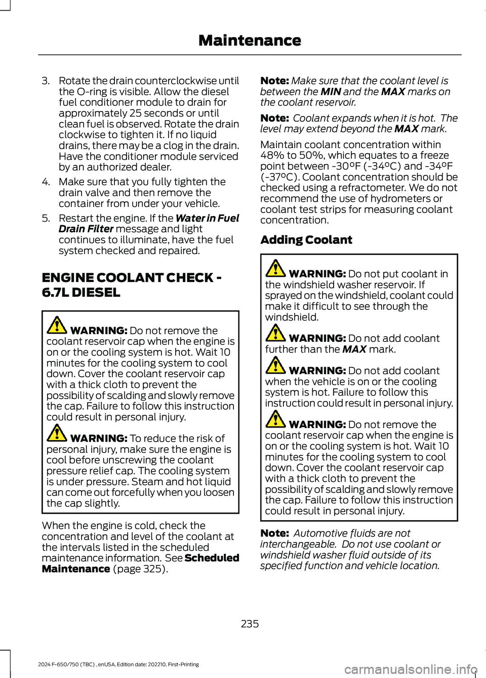
3.Rotate the drain counterclockwise untilthe O-ring is visible. Allow the dieselfuel conditioner module to drain forapproximately 25 seconds or untilclean fuel is observed. Rotate the drainclockwise to tighten it. If no liquiddrains, there may be a clog in the drain.Have the conditioner module servicedby an authorized dealer.
4.Make sure that you fully tighten thedrain valve and then remove thecontainer from under your vehicle.
5.Restart the engine. If the Water in FuelDrain Filter message and lightcontinues to illuminate, have the fuelsystem checked and repaired.
ENGINE COOLANT CHECK -
6.7L DIESEL
WARNING: Do not remove thecoolant reservoir cap when the engine ison or the cooling system is hot. Wait 10minutes for the cooling system to cooldown. Cover the coolant reservoir capwith a thick cloth to prevent thepossibility of scalding and slowly removethe cap. Failure to follow this instructioncould result in personal injury.
WARNING: To reduce the risk ofpersonal injury, make sure the engine iscool before unscrewing the coolantpressure relief cap. The cooling systemis under pressure. Steam and hot liquidcan come out forcefully when you loosenthe cap slightly.
When the engine is cold, check theconcentration and level of the coolant atthe intervals listed in the scheduledmaintenance information. See ScheduledMaintenance (page 325).
Note:Make sure that the coolant level isbetween the MIN and the MAX marks onthe coolant reservoir.
Note: Coolant expands when it is hot. Thelevel may extend beyond the MAX mark.
Maintain coolant concentration within48% to 50%, which equates to a freezepoint between -30°F (-34°C) and -34°F(-37°C). Coolant concentration should bechecked using a refractometer. We do notrecommend the use of hydrometers orcoolant test strips for measuring coolantconcentration.
Adding Coolant
WARNING: Do not put coolant inthe windshield washer reservoir. Ifsprayed on the windshield, coolant couldmake it difficult to see through thewindshield.
WARNING: Do not add coolantfurther than the MAX mark.
WARNING: Do not add coolantwhen the vehicle is on or the coolingsystem is hot. Failure to follow thisinstruction could result in personal injury.
WARNING: Do not remove thecoolant reservoir cap when the engine ison or the cooling system is hot. Wait 10minutes for the cooling system to cooldown. Cover the coolant reservoir capwith a thick cloth to prevent thepossibility of scalding and slowly removethe cap. Failure to follow this instructioncould result in personal injury.
Note: Automotive fluids are notinterchangeable. Do not use coolant orwindshield washer fluid outside of itsspecified function and vehicle location.
235
2024 F-650/750 (TBC) , enUSA, Edition date: 202210, First-PrintingMaintenance
Page 242 of 386
Follow your community’s regulations andstandards for recycling and disposing ofautomotive fluids.
Severe Climates
If you drive in extremely cold climates:
•It may be necessary to increase thecoolant concentration above 50%.
•A coolant concentration of 60%provides improved freeze pointprotection.Coolant concentrationsabove 60% decrease the overheatprotection characteristics of thecoolant and may cause enginedamage.
If you drive in extremely hot climates:
•You can decrease the coolantconcentration to 40%.
•Coolant concentrations below 40%decrease the freeze and corrosionprotection characteristics of thecoolant and may cause enginedamage.
Vehicles driven year-round in non-extremeclimates should use prediluted enginecoolant for optimum cooling system andengine protection.
Coolant Change
At specific mileage intervals, as listed inthe scheduled maintenance information,the coolant should be changed. Theinstrument cluster display may display amessage to change coolant at this time.Add prediluted coolant approved to thecorrect specification. See Capacities andSpecifications (page 291).
Engine-driven Cooling Fan (FanClutch)
Your vehicle may have an engine drivencooling fan drive (also called a fan clutch).This fan drive changes the fan speed tomatch the vehicle’s changing cooling airflow requirements. Fan speed, fan noiselevel and fuel consumption all increasebased on the driving conditions thatinclude trailer towing, hill climbing, heavyloads, high speed and high ambienttemperature, individually or in combination.
The fan drive is designed to provide theminimum fan speed (and resultingminimum fan noise and fuel consumption)required to meet the ever changing vehiclecooling air flow requirements. You can hearfan noise increasing and decreasing as theengine power requirements and vehicledriving conditions change as you drive. Thisis to be expected as being normal to theoperation of your vehicle. High levels of fannoise might also be heard when yourengine is first started, and should normallydecrease after driving for a short time.
ENGINE COOLANT CHECK -
7.3L
WARNING: Do not remove thecoolant reservoir cap when the engine ison or the cooling system is hot. Wait 10minutes for the cooling system to cooldown. Cover the coolant reservoir capwith a thick cloth to prevent thepossibility of scalding and slowly removethe cap. Failure to follow this instructioncould result in personal injury.
WARNING: Do not put coolant inthe windshield washer reservoir. Ifsprayed on the windshield, coolant couldmake it difficult to see through thewindshield.
238
2024 F-650/750 (TBC) , enUSA, Edition date: 202210, First-PrintingMaintenance