2024 FORD F650/750 fuse
[x] Cancel search: fusePage 215 of 386

CHANGING A FUSE
Fuses
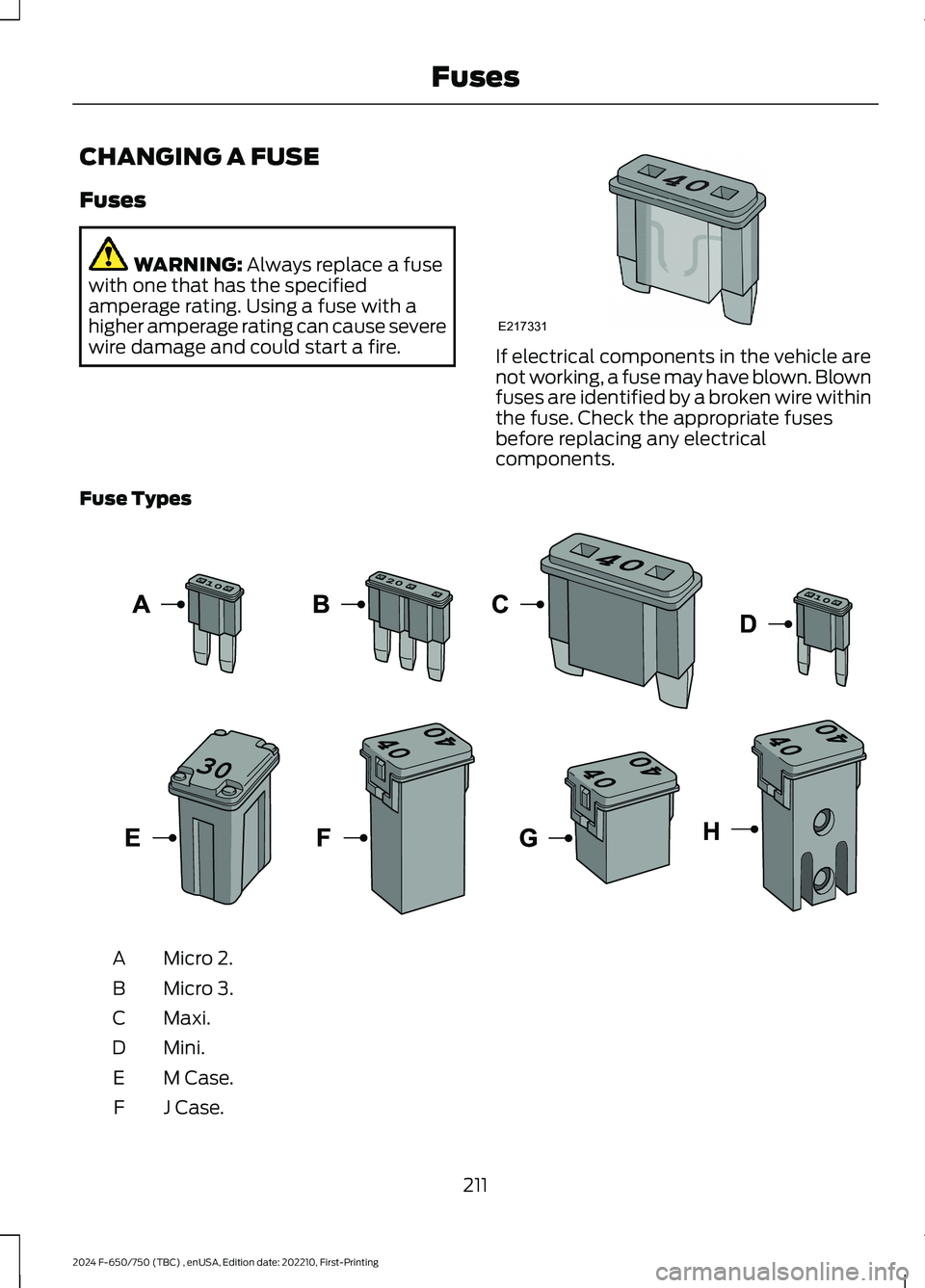
WARNING: Always replace a fusewith one that has the specifiedamperage rating. Using a fuse with ahigher amperage rating can cause severewire damage and could start a fire.If electrical components in the vehicle arenot working, a fuse may have blown. Blownfuses are identified by a broken wire withinthe fuse. Check the appropriate fusesbefore replacing any electricalcomponents.
Fuse Types
Micro 2.A
Micro 3.B
Maxi.C
Mini.D
M Case.E
J Case.F
211
2024 F-650/750 (TBC) , enUSA, Edition date: 202210, First-PrintingFusesE217331 E267379
Page 216 of 386

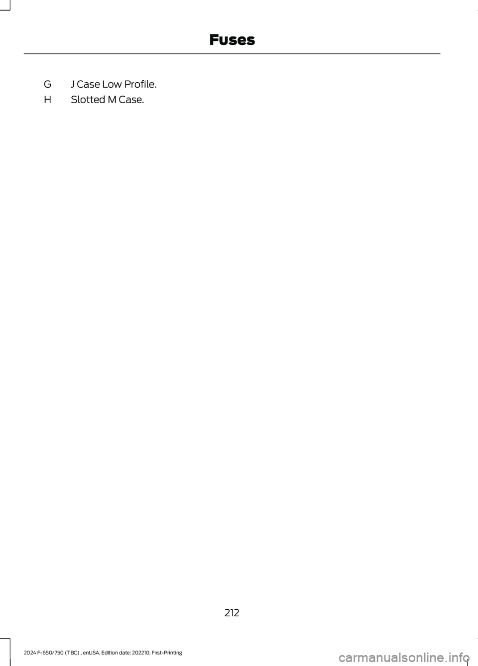
J Case Low Profile.G
Slotted M Case.H
212
2024 F-650/750 (TBC) , enUSA, Edition date: 202210, First-PrintingFuses
Page 218 of 386

Engine compartment (with engine off)
Inspect for glazing, fraying or cracking. There should be nomore than 5-7 cracks per rib, per 1 in (2.5 cm)Belts (fan, alternator,water pump and airconditioningcompressor)
Inspect for signs of fluid puddles or dripping fluid on theground under the engine, or the underside of the engine.Fluid leaks
Inspect for debris that may have collected on the HVAC airinlet grille or inside the exterior module as this may reducesystem performance.
HVAC air inlet
Engine starting (with parking brake applied)
Before entering the cab, verify that the vehicle is equippedwith spare electrical fuses (if used), three red reflectivetriangles, a properly charged and rated fire extinguisher andwheel chocks.
Safety and emergencyequipment
Walk around the vehicle and verify all steps and grab handles,inside and out (as well as behind), are tight and clean. Useextreme caution and a three-point stance at all times.
Inspect door latches for proper closing, latching and locking.
Set the parking brake. Make sure the gearshift lever is inneutral (N) or park (P) (if equipped with a park position).Starting the engine
Diesel engine: Turn the key to the on position. Turn the keyto start when the wait to start indicator light in the instrumentcluster turns off.
Gasoline engine: Turn the key to start, and then release itas soon as the engine starts.
Verify pressure builds to normal operating range.Engine oil pressure
A tone indicating low air pressure should sound immediatelyafter the engine starts but before the compressor has built-up pressure. The tone should stop when the air pressurereaches 70 psi (483 kPa). Let the air pressure build togoverned cutout pressure, which should occur between115–130 psi (793–896 kPa).
Low air pressure warningtone (if equipped with anair compressor)
Press the accelerator and verify that it operates smoothly,without any binding or irregular feel. Release the pedal andverify the engine returns to idle speed immediately.
Accelerator
214
2024 F-650/750 (TBC) , enUSA, Edition date: 202210, First-PrintingVehicle Inspection Guide
Page 229 of 386

UNDER HOOD OVERVIEW - 6.7L DIESEL
Engine compartment fuse box. See Fuses (page 202).A
Windshield washer fluid reservoir. See Washer Fluid Check (page 249).B
Secondary Cooling System Reservoir. See Engine Coolant Check (page 235).C
Engine coolant reservoir. See Engine Coolant Check (page 235).D
Secondary fuel filter. See Draining the Fuel Filter Water Trap (page 234).E
Engine oil separator. See Changing the Engine Oil and Oil Filter (page 228).F
Engine oil filler cap. See Engine Oil Check (page 227).G
Brake fluid reservoir. See Brake Fluid Check (page 245).H
Power steering fluid reservoir. See Power Steering Fluid Check (page 246).I
Air brake compressor. See Brake System Inspection (page 256).J
Engine oil dipstick. See Engine Oil Dipstick (page 227).K
Air cleaner assembly. See Changing the Engine Air Filter (page 230).L
225
2024 F-650/750 (TBC) , enUSA, Edition date: 202210, First-PrintingMaintenanceE389955
Page 230 of 386

UNDER HOOD OVERVIEW - 7.3L
Engine compartment fuse box. See Fuses (page 202).A
Engine oil dipstick. See Engine Oil Dipstick (page 227).B
Windshield washer fluid reservoir. See Washer Fluid Check (page 249).C
Automatic transmission fluid dipstick. See Automatic Transmission FluidCheck (page 243).D
Engine coolant reservoir. See Engine Coolant Check (page 238).E
Engine oil filler cap. See Engine Oil Check (page 227).F
Brake fluid reservoir. See Brake Fluid Check (page 245).G
Power steering fluid reservoir. See Power Steering Fluid Check (page 246).H
Air cleaner assembly. See Changing the Engine Air Filter (page 232).I
226
2024 F-650/750 (TBC) , enUSA, Edition date: 202210, First-PrintingMaintenanceE330964
Page 255 of 386

Headlamp bulbs must be marked with anauthorized D.O.T. marking for NorthAmerica to make sure they have the properlamp performance, light brightness, lightpattern and safe visibility.
Install in the reverse order unless otherwisestated.
Headlamp Bulbs
1.Switch all of the lamps and the ignitionoff.
2.Remove the headlamp. SeeRemoving a Headlamp (page 250).
3.Release the clip and remove the bulb.
Note:Do not touch the bulb glass.
Note:If the bulb is accidentally touched, itshould be cleaned with rubbing alcoholbefore being used.
Front Clearance and IdentificationLamp (If Equipped)
1.Switch all of the lamps and the ignitionoff.
2.Remove the screw and lens from thelamp assembly.
3.Press the bulb in and turn the bulbcounterclockwise to remove it.
Brake Lamp, Rear Lamp, RearDirection Indicator, License PlateLamp and Reverse Lamp
1.Switch all of the lamps and the ignitionoff.
2.Remove the four screws and the lamplens from lamp assembly.
3.Remove the bulb by pulling it straightout.
CHANGING THE ENGINE-
MOUNTED AND DIESEL FUEL
CONDITIONER MODULE FUEL
FILTERS - 6.7L DIESEL
WARNING: Do not dispose of fuelin the household refuse or the publicsewage system. Use an authorized wastedisposal facility.
Your vehicle has two fuel filters. The firstfilter mounts on top of the engine on theleft-hand side. The second filter is insidethe diesel fuel conditioner module. Themodule is mounted between the inboardside of the fuel tank and the frame rail.
251
2024 F-650/750 (TBC) , enUSA, Edition date: 202210, First-PrintingMaintenanceE163825 E163828
Page 260 of 386

BRAKE SYSTEM INSPECTION
WARNING: Always wear arespirator approved by the NationalInstitute of Occupational Studies ofHealth (NIOSH) or Mine Safety andAppliance (MSA) during all brake serviceprocedures. Wear the respirator fromremoval of the wheels through assembly.Never use compressed air or dry brushingto clean brake parts or assemblies.Clean brake parts and assemblies inopen air. During assembly, carefullyplace all parts on the floor to avoidgetting dust in the air. Use an industrialvacuum cleaner with a HEPA filtersystem to clean dust from the brakedrums, backing plates and other brakeparts. After using the vacuum, removeany remaining dust with a rag soaked inwater and wrung until nearly dry.Never use compressed air or drysweeping to clean the work area. Use anindustrial vacuum cleaner with a HEPAfilter system and rags soaked in waterand wrung until nearly dry. Dispose ofused rags with care to avoid getting dustin the air. Use an approved respiratorwhen emptying vacuum cleaners andhandling used rags.Worker clean-up: Wash your handsbefore eating, drinking or smoking.Vacuum your work clothes after use andthen launder them separately, withoutshaking them, to prevent fiber dustgetting into the air.
Your vehicle is equipped withnon-asbestos brake linings. However,exposure to excessive amounts of brakematerial (whether asbestos ornon-asbestos, fiberglass, mineral wool,aramid or carbon) may be a serious healthhazard.
Air Brakes
WARNING: Do not manually adjustthe automatic slack adjusters to correctexcessive push rod stroke as it may resultin reduced brake effectiveness and avehicle crash. Excessive push rod strokeindicates that a problem exists with theautomatic adjuster, with the installationof the adjuster, or with foundation brakecomponents that manual adjustmentdoes not remedy. Seek service from aqualified facility for excessive push rodstroke.
Inspection and Adjustment
Establish a regular schedule for periodiccleaning, lubrication and adjustmentinspection based on vehicle use. Exactmaintenance intervals are difficult topredetermine due to vehicle applicationsand operating conditions. If you areuncertain of the proper schedule for yourvehicle, contact an authorized dealer.
Regular inspections should include:
•Periodic checking (every serviceinterval) of push rod travel or brakeadjustment. This is essential foreffective braking. Brake chamber pushrods on original equipment chambersnow incorporate an orange paintmarker near the base of the push rod
256
2024 F-650/750 (TBC) , enUSA, Edition date: 202210, First-PrintingMaintenance
Page 325 of 386

AUXILIARY SWITCHES (IF
EQUIPPED)
For maximum vehicle performance, keepthe following information in mind whenadding accessories or equipment to yourvehicle:
•When adding accessories, equipment,passengers and luggage to yourvehicle, do not exceed the total weightcapacity of the vehicle or of the frontor rear axle (GVWR or GAWR asindicated on the Safety ComplianceCertification label). Ask an authorizeddealer for specific weight information.
•The Federal CommunicationsCommission (FCC) and CanadianRadio TelecommunicationsCommission (CRTC) regulate the useof mobile communications systemsequipped with radio transmitters, forexample, two-way radios, telephonesand theft alarms. Any such equipmentinstalled in your vehicle should complywith Federal CommunicationsCommission (FCC) and CanadianRadio TelecommunicationsCommission (CRTC) regulations, andshould be installed by an authorizeddealer.
•An authorized dealer needs to installmobile communications systems.Improper installation may harm theoperation of your vehicle, particularlyif the manufacturer did not design themobile communication systemspecifically for automotive use.
•If you or an authorized Ford dealer addany non-Ford electrical or electronicaccessories or components to yourvehicle, you may adversely affectbattery performance and durability. Inaddition, you may also adversely affectthe performance of other electricalsystems in the vehicle.
The auxiliary switch option packageprovides four switches, mounted in thecenter of the instrument panel. Theseswitches operate when the ignition is onor from battery power, depending on theswitchable power distribution box fuselocations #82 and #83. We recommend,however, that the engine remain runningto maintain battery charge when using theauxiliary switches for extended periods oftime or higher current draws.
Note:When your vehicle has a dieselengine, use the auxiliary switches only whilethe engine is running. The glow plugs alsodrain battery power when the ignition key isin the on position. Using the auxiliaryswitches, even for limited amounts of time,can cause your battery to drain quickly andprevent your vehicle from restarting.
When switched on, the auxiliary switchesprovide 20 amps or 40 amps of electricalbattery power for a variety of personal orcommercial uses.
The relays for the auxiliary switches are inthe power distribution box under the hoodby the right-hand fender. See yourauthorized dealer for service.
Each switch includes a power lead, ablunt-cut and sealed wire below theinstrument panel and to the left of thesteering column in the driver footwell area.
The power leads are coded as shown:
321
2024 F-650/750 (TBC) , enUSA, Edition date: 202210, First-PrintingAccessoriesE163431