2023 TOYOTA VENZA HYBRID air condition
[x] Cancel search: air conditionPage 337 of 560
3375-1. Using the air conditioning system and defogger
5
Interior features
*: If equipped
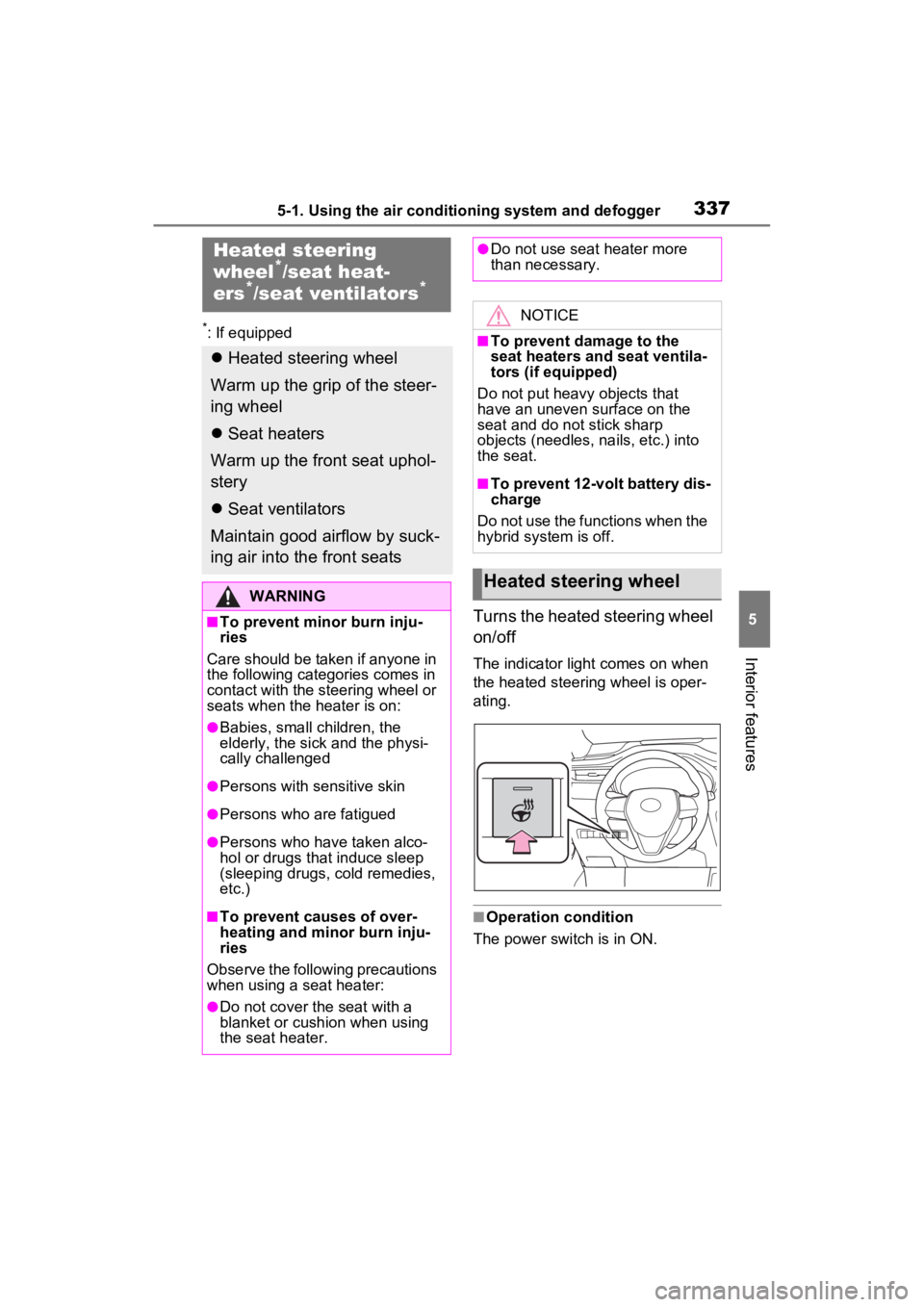
Turns the heated steering wheel
on/off
The indicator light comes on when
the heated steering wheel is oper-
ating.
■Operation condition
The power switch is in ON.
Heated steering
wheel*/seat heat-
ers*/seat ventilators*
Heated steering wheel
Warm up the grip of the steer-
ing wheel
Seat heaters
Warm up the front seat uphol-
stery
Seat ventilators
Maintain good airflow by suck-
ing air into the front seats
WARNING
■To prevent minor burn inju-
ries
Care should be taken if anyone in
the following categories comes in
contact with the steering wheel or
seats when the heater is on:
●Babies, small children, the
elderly, the sick and the physi-
cally challenged
●Persons with sensitive skin
●Persons who are fatigued
●Persons who have taken alco-
hol or drugs that induce sleep
(sleeping drugs, cold remedies,
etc.)
■To prevent causes of over-
heating and minor burn inju-
ries
Observe the following precautions
when using a seat heater:
●Do not cover the seat with a
blanket or cushion when using
the seat heater.
●Do not use seat heater more
than necessary.
NOTICE
■To prevent damage to the
seat heaters and seat ventila-
tors (if equipped)
Do not put heavy objects that
have an uneven surface on the
seat and do not stick sharp
objects (needles, nails, etc.) into
the seat.
■To prevent 12-volt battery dis-
charge
Do not use the functions when the
hybrid system is off.
Heated steering wheel
Page 338 of 560
3385-1. Using the air conditioning system and defogger
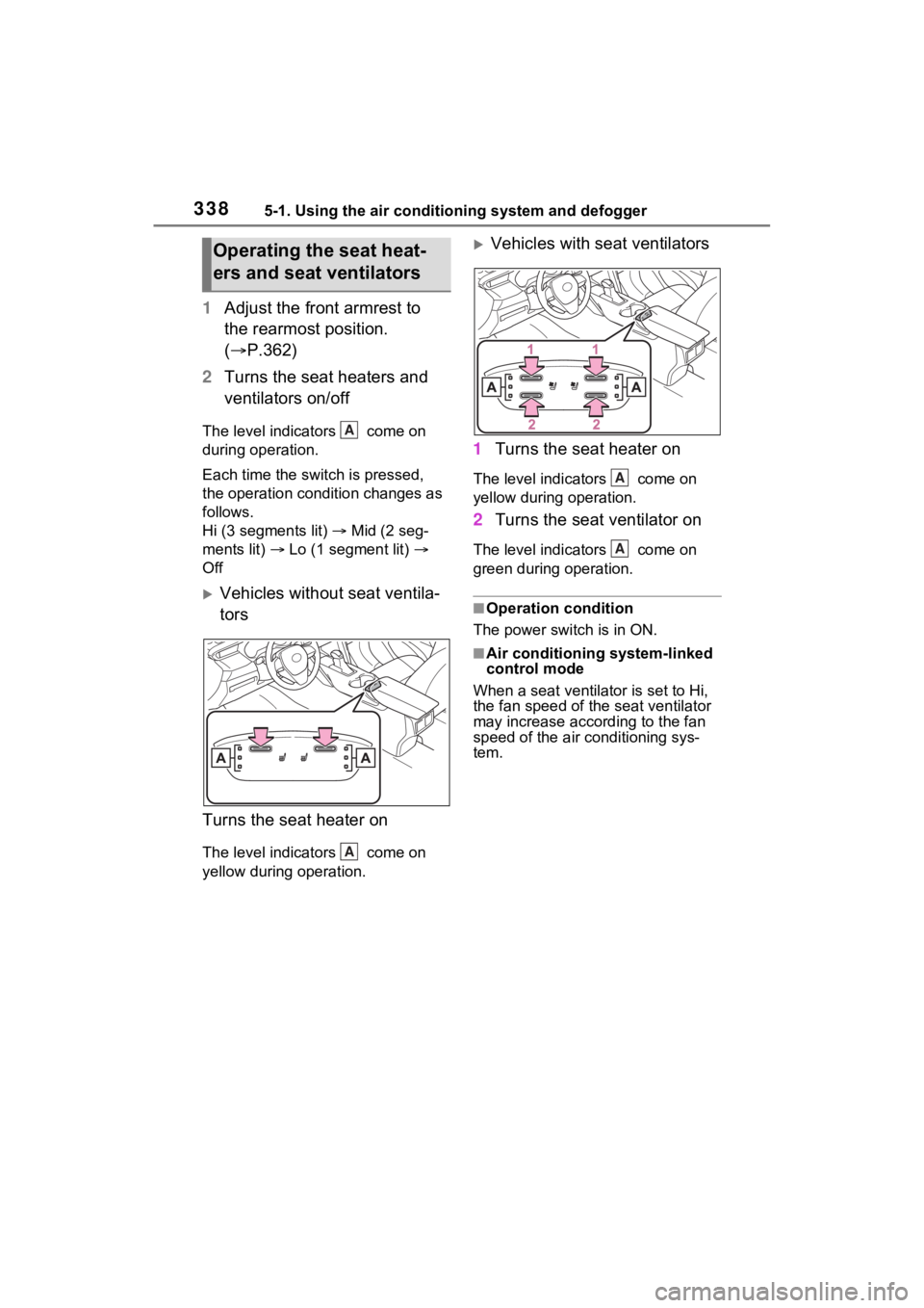
1Adjust the front armrest to
the rearmost position.
( P.362)
2 Turns the seat heaters and
ventilators on/off
The level indicators come on
during operation.
Each time the switch is pressed,
the operation condition changes as
follows.
Hi (3 segments lit) Mid (2 seg-
ments lit) Lo (1 segment lit)
Off
Vehicles without seat ventila-
tors
Turns the seat heater on
The level indicators come on
yellow during operation.
Vehicles with seat ventilators
1 Turns the seat heater on
The level indica tors come on
yellow during operation.
2 Turns the seat ventilator on
The level indica tors come on
green during operation.
■Operation condition
The power switch is in ON.
■Air conditioning system-linked
control mode
When a seat ventilator is set to Hi,
the fan speed of the seat ventilator
may increase according to the fan
speed of the air conditioning sys-
tem.
Operating the seat heat-
ers and seat ventilators
A
A
A
A
Page 340 of 560
3405-2. Using the interior lights
tronic key, whether the doors are
locked/unlocked, and whether the
doors are opened/closed.
●If the interior lights remain on
when the power switch is turned to
OFF, the lights will go off automat-
ically after 20 minutes.
■Interior lights brightness reduc-
tion
The brightness of the following
lights will be reduc ed when shifting
the shift lever to any position other
than P.
●Instrument panel lower illumina-
tion (if equipped)
●Footwell lights (if equipped)
●Upper console lights (if equipped)
●Front console light
●Inside door handle lights (if
equipped)
■The interior lights may turn on
automatically when
If any of the SRS airbags deploy
(inflate) or in the event of a strong
rear impact, the interior lights will
turn on automatically.
The interior lights will turn off auto-
matically after approximately 20
minutes.
The interior lights can be turned off
manually. However, in order to help
prevent further collisions, it is rec-
ommended that they be left on until
safety can be ensured.
(The interior lights may not turn on
automatically depending on the
force of the impact and conditions of
the collision.)
■When the illuminated entry sys-
tem do not turn on
The electronic key battery-saving
function may be activated.( P.155)
■Customization
Setting (e.g. the time elapsed before
the lights turn off) can be changed.
(Customizable features: P.513)
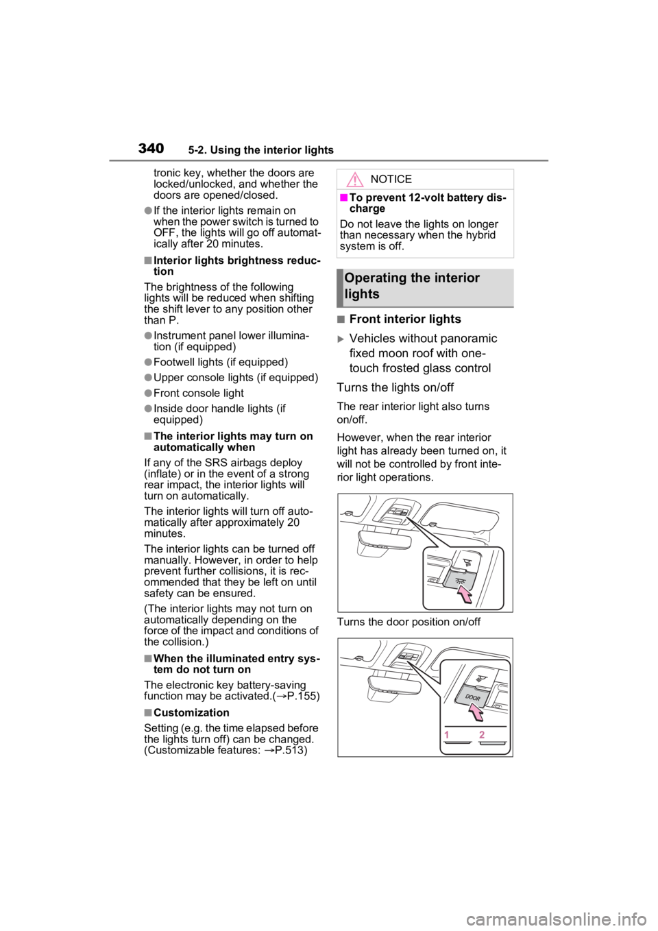
■Front interior lights
Vehicles without panoramic
fixed moon roof with one-
touch frosted glass control
Turns the lights on/off
The rear interior light also turns
on/off.
However, when the rear interior
light has already been turned on, it
will not be controlle d by front inte-
rior light operations.
Turns the door position on/off
NOTICE
■To prevent 12-volt battery dis-
charge
Do not leave the lights on longer
than necessary when the hybrid
system is off.
Operating the interior
lights
Page 371 of 560
371
6
6
Maintenance and care
Maintenance and care
6-1. Maintenance and careCleaning and protecting the vehicle exterior .......... 372
Cleaning and protecting the vehicle interior ........... 376
6-2. Maintenance Maintenance requirements.................................. 379
General maintenance.. 381
Emission inspection and maintenance (I/M) pro-
grams ........................ 383
6-3. Do-it-yourself mainte- nance
Do-it-yourself service pre- cautions ..................... 385
Hood ........................... 387
Positioning a floor jack 388
Engine compartment ... 390
12-volt battery ............. 397
Tires ............................ 400
Tire inflation pressure . 412
Wheels ......... ...............414
Air conditioning filter .... 415
Cleaning the hybrid battery (traction battery) air intake
vent ........................... 417
Wiper insert replacement .................................. 421
Electronic key battery.. 424
Checking and replacing fuses.......................... 426Headlight aim ..............
429
Exterior lights .............. 430
Page 375 of 560
3756-1. Maintenance and care
6
Maintenance and care
NOTICE
■Cleaning the radiator grille
Observe the following precautions
to avoid damage to the radiator
grille surface.
●Do not use a hard brush. Use a
soft cloth or sponge to wipe.
●Remove any dirt by using a
neutral detergent. Do not use
waxes or alcohols (e.g. glass
cleaner).
●Wash detergent off with water
after washing the vehicle.
■When using an automatic car
wash (vehicles with rain-
sensing windshield wipers)
Set the wiper switch to off posi-
tion.
If the wiper switch is in “AUTO”,
the wipers may operate and the
wiper blades may be damaged.
■When using a high pressure
car wash
●When washing the vehicle, do
not spray the came ra or its sur-
rounding area directly with a
high pressure washer. Shock
applied from high pressure
water may cause the device to
not operate normally.
●Do not spray water directly on
the radar which is equipped
behind the radar sensor cover.
Otherwise it may cause the
device to be damaged.
●Do not bring the nozzle tip close
to boots (rubber or resin manu-
factured cover), connectors or
the following parts. The parts
may be damaged if they come
into contact with high-pressure
water.
• Traction re lated parts
• Steering parts
• Suspension parts
• Brake parts
●Keep the cleaning nozzle at
least 11.9 in. (30 cm) away from
the vehicle body. Otherwise
resin section, s uch as moldings
and bumpers, may be deformed
and damaged. Also, do not con-
tinuously hold the nozzle in the
same place.
●Do not spray the lower part of
the windshield continuously. If
water enters the air conditioning
system intake located near the
lower part of the windshield, the
air conditioning system may not
operate correctly.
●Do not wash the underside of
the vehicle using a high pres-
sure car washer.
Page 394 of 560
3946-3. Do-it-yourself maintenance
borate coolant with long-life hybrid
organic acid technology.
U.S.A.:
“Toyota Super Long Life Coolant” is
a mixture of 50% coolant and 50%
deionized water. (Minimum tem-
perature: -31°F [-35°C])
Canada:
“Toyota Super Long Life Coolant” is
a mixture of 55% coolant and 45%
deionized water. (Minimum tem-
perature: -44°F [-42°C])
For more details about coolant, con-
tact your Toyota dealer.
■If the coolant level drops within
a short time of replenishing
Visually check the radiators, hoses,
engine/power control unit coolant
reservoir caps, drain cock and water
pump.
If you cannot find a leak, have your
Toyota dealer, t est the cap and
check for leaks in the cooling sys-
tem.
Check the radiator and con-
denser, and clear away any for-
eign objects.
If either of the above parts is
extremely dirty or you are not
sure of their condition, have
your vehicle inspected by your
Toyota dealer.
■Checking fluid level
The brake fluid level should be
between the “MAX” and “MIN”
WARNING
■When the hybrid system is
hot
Do not remove the engine/power
control unit coolant reservoir caps
or the radiator cap.
The cooling system may be under
pressure and may spray hot cool-
ant if the cap is removed, causing
serious injuries, such as burns.
NOTICE
■When adding coolant
Coolant is neither plain water nor
straight antifreeze. The correct
mixture of water and antifreeze
must be used to provide proper
lubrication, corrosion protection
and cooling. Be sure to read the
antifreeze or coolant label.
■If you spill coolant
Be sure to wash it off with water to
prevent it from damaging parts or
paint.
Checking the radiator and
condenser
WARNING
■When the hybrid system is
hot
Do not touch the radiator or con-
denser as they may be hot and
cause serious injuries, such as
burns.
■When the electric cooling fan
is operating
Do not touch the engine compart-
ment.
With the power switch in ON, the
electric cooling fa n may automati-
cally start to run if the air condi-
tioning is on and/or the coolant
temperature is high. Be sure the
power switch is OFF when work-
ing near the electric cooling fan or
radiator grille.
Checking and adding the
brake fluid
Page 400 of 560
4006-3. Do-it-yourself maintenance
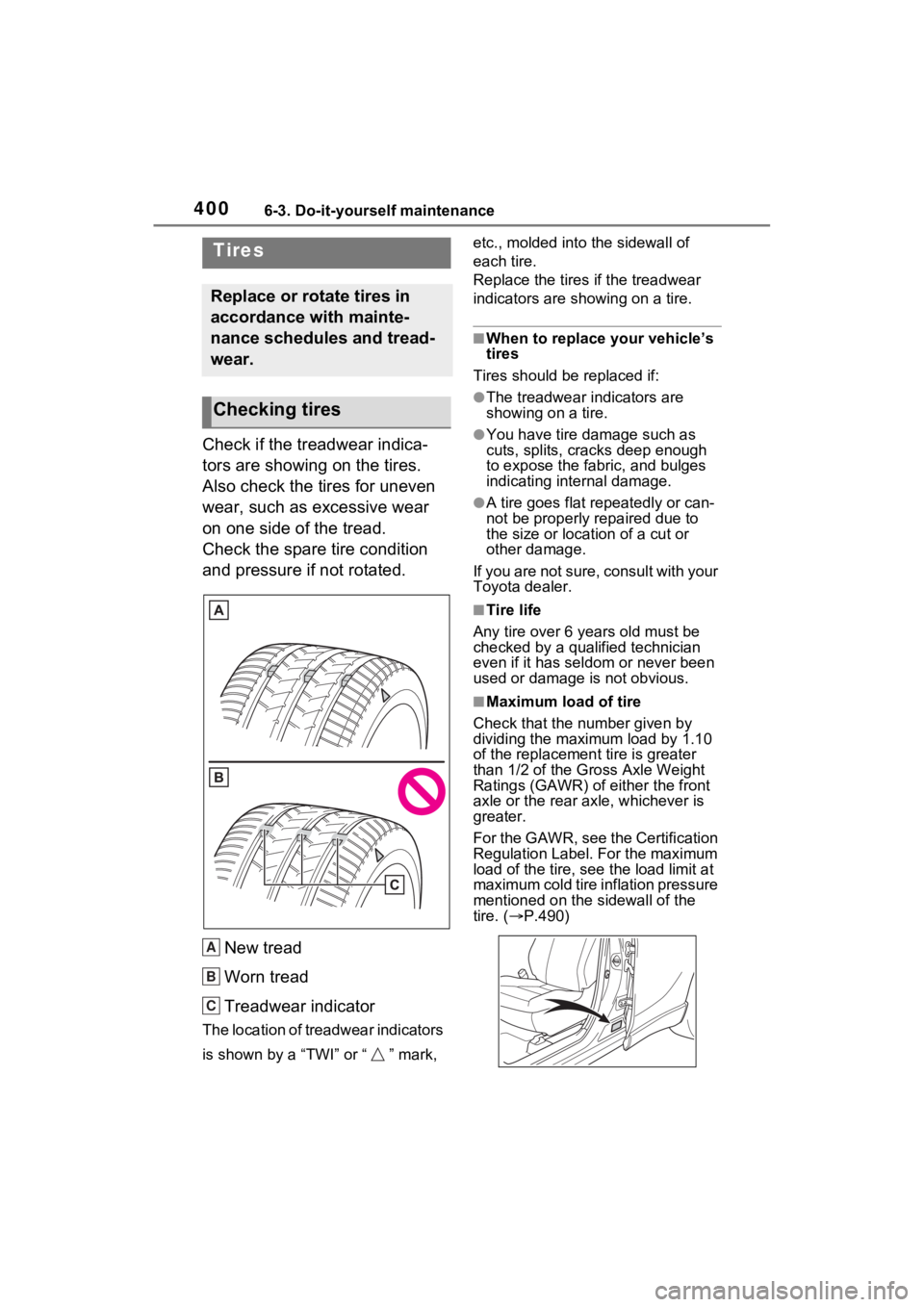
Check if the treadwear indica-
tors are showing on the tires.
Also check the tires for uneven
wear, such as excessive wear
on one side of the tread.
Check the spare tire condition
and pressure if not rotated.
New tread
Worn tread
Treadwear indicator
The location of treadwear indicators
is shown by a “TWI” or “ ” mark, etc., molded into the sidewall of
each tire.
Replace the tires if the treadwear
indicators are s
howing on a tire.
■When to replace your vehicle’s
tires
Tires should be replaced if:
●The treadwear indicators are
showing on a tire.
●You have tire damage such as
cuts, splits, cracks deep enough
to expose the fabric, and bulges
indicating internal damage.
●A tire goes flat repeatedly or can-
not be properly repaired due to
the size or location of a cut or
other damage.
If you are not sure, consult with your
Toyota dealer.
■Tire life
Any tire over 6 years old must be
checked by a qualified technician
even if it has seldom or never been
used or damage is not obvious.
■Maximum load of tire
Check that the n umber given by
dividing the maximum load by 1.10
of the replacement tire is greater
than 1/2 of the Gross Axle Weight
Ratings (GAWR) of either the front
axle or the rear axle, whichever is
greater.
For the GAWR, see the Certification
Regulation Label. For the maximum
load of the tire, see the load limit at
maximum cold tire in flation pressure
mentioned on the sidewall of the
tire. ( P.490)
Tires
Replace or rotate tires in
accordance with mainte-
nance schedules and tread-
wear.
Checking tires
A
B
C
Page 404 of 560

4046-3. Do-it-yourself maintenance
3Press and hold to display
the cursor on the content dis-
play area (center) of the
multi-information display.
4 Press or of the meter
control switches to select
and then press .
5 Press or of the meter
control switches and select
, and then press .
6 Press or of the meter
control switches and select
“TPWS”, and then press .
7 Press or to select
“Pressure unit setting”.
8 Press or to select the
desired unit and then press
.
■Routine tire inflation pressure
checks
The tire pressure warning system
does not replace routine tire inflation
pressure checks. Make sure to
check tire inflation pressure as part
of your routine of daily vehicle
checks.
■Tire inflation pressure
●It may take a few minutes to dis-
play the tire inflation pressure
after the power switch is turned to
ON. It may also take a few min-
utes to display the tire inflation
pressure after inflation pressure
has been adjusted.
●Tire inflation p ressure changes
with temperature.
The displayed values may also be
different from th e values mea-
sured using a tire pressure gauge.
■Situations in which the tire
pressure warning system may
not operate properly
●In the following cases, the tire
pressure warning system may not
operate properly.
• If non-genuine Toyota wheels are used.
• A tire has been replaced with a tire that is not an OE (Original
Equipment) tire.
• A tire has been replaced with a tire that is not of the specified size.
• Tire chains, etc. are equipped.
• An auxiliary-support ed run-flat tire
is equipped.
• If a window tint that affects the
radio wave signals is installed.
• If there is a lot of snow or ice on the vehicle, particularly around the
wheels or wheel housings.
• If the tire inflation pressure is extremely higher than the speci-
fied level.
• If wheels without tire pressure warning valves and transmitters
are used.
• If the ID code on the tire pressure warning valves and transmitters is
not registered in the tire pressure
warning computer.
●Performance may be affected in
the following situations.
• Near a TV tower, electric power
plant, gas station, radio station,
large display, airpo rt or other facil-
ity that generates strong radio
waves or electrical noise
• When carrying a portable radio, cellular phone, cordless phone or
other wireless communication
device
If tire position information is not
correctly displayed due to the
radio wave conditions, the display
may be corrected by driving and
changing the radio wave condi-
tions.
●When the vehicle is parked, the
time taken for the warning to start
or go off could be extended.
●When tire inflation pressure