2023 TOYOTA TUNDRA HYBRID turn signal
[x] Cancel search: turn signalPage 260 of 618
2604-5. Using the driving support systems
Owners Manual_USA_M0C052_encontrol continues to keep your vehicle stopped.
When the turn signal lever is ope
rated and your vehicle moves to an over-
taking lane while driving at 50 mph (80 km/h) or more, the vehi cle will accel-
erate to help to overt ake a passing vehicle.
The system’s identification of what is an overtaking lane may be determined
solely based on the location of the steering wheel in the vehicle (left side
driver position versus right side driver position.) If the vehi cle is driven to a
region where the overtaking lane is on a different side from wh ere the vehi-
cle is normally driven, the vehicle may accelerate when the tur n signal lever
is operated in the opposite direction to the overtaking lane (e .g., if the driver
normally operates the vehicle in a region where the overtaking lane is to the
right but then drives to a region where the overtaking lane is to the left, the
vehicle may accelerate when the right turn signal is activated).
Example of acceleration
When there are no longer any preceding vehicles driving slower
than the set speed
The system accelerates until the set speed is reached. The system then
returns to constan t speed cruising.
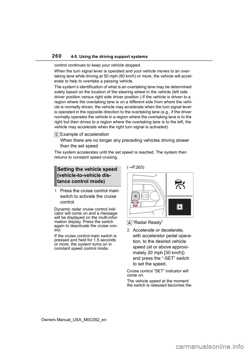
1Press the cruise control main
switch to activate the cruise
control.
Dynamic radar cruise control indi-
cator will come on and a message
will be displayed on the multi-infor-
mation display. Press the switch
again to deactivate the cruise con-
trol.
If the cruise cont rol main switch is
pressed and held for 1.5 seconds
or more, the syste m turns on in
constant speed control mode. (
P.263)
“Radar Ready”
2 Accelerate or decelerate,
with accelerator pedal opera-
tion, to the desired vehicle
speed (at or above approxi-
mately 20 mph [30 km/h])
and press the “-SET” switch
to set the speed.
Cruise control “SET” indicator will
come on.
The vehicle speed at the moment
the switch is released becomes the
Setting the vehicle speed
(vehicle-to-vehicle dis-
tance control mode)
Page 268 of 618

2684-5. Using the driving support systems
Owners Manual_USA_M0C052_en
Meter control switches
Turning the Blind Spot Monitor
on/off.
Outside rear view mirror indi-
cators
When a vehicle is detected in a
blind spot of the outside rear view
mirrors or approaching rapidly from
behind into a blind spot, the outside
rear view mirror indicator on the
detected side will illuminate. If the
turn signal lever is operated toward
the detected side, the outside rear
view mirror indicator flashes.
■Outside rear view mirror indica-
tor visibility
In strong sunlight, the outside rear
view mirror indicato r may be difficult
to see.
■When “Blind Spot Monitor
Unavailable” is shown on the
multi-information display
Ice, snow, mud, etc., may be
attached to the rear bumper around
the sensors. ( P.269) The system
should return to normal operation
after removing the ice, snow, mud,
etc., from the rear bumper. Addition-
ally, the sensors may not operate
normally when driving in extremely
hot or cold environments.
■When “Blind Spot Monitor Mal-
function Visit Your Dealer” is
shown on the multi-information
display
There may be a sensor malfunction
or misaligned. Have the vehicle
inspected by your Toyota dealer.
■Customization
Some functions can be customized.
( P.568)
■Certification
P.614
System components
WARNING
■To ensure the system can
operate properly
Blind Spot Monitor sensors are
installed behind the left and right
sides of the rear bumper respec-
tively. Observe the following to
ensure the Blind Spot Monitor can
operate correctly.
Page 308 of 618
3084-5. Using the driving support systems
Owners Manual_USA_M0C052_en
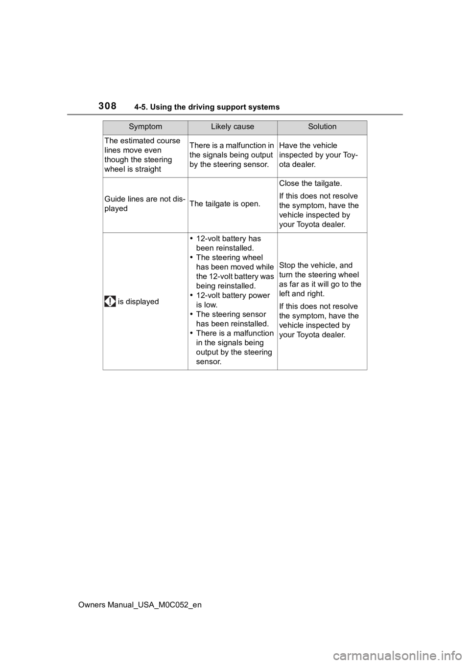
The estimated course
lines move even
though the steering
wheel is straightThere is a malfunction in
the signals being output
by the steering sensor.Have the vehicle
inspected by your Toy-
ota dealer.
Guide lines are not dis-
playedThe tailgate is open.
Close the tailgate.
If this does not resolve
the symptom, have the
vehicle inspected by
your Toyota dealer.
is displayed
12-volt battery has
been reinstalled.
The steering wheel
has been moved while
the 12-volt battery was
being reinstalled.
12-volt battery power
is low.
The steering sensor
has been reinstalled.
There is a malfunction
in the signals being
output by the steering
sensor.
Stop the vehicle, and
turn the steering wheel
as far as it will go to the
left and right.
If this does not resolve
the symptom, have the
vehicle inspected by
your Toyota dealer.
SymptomLikely causeSolution
Page 436 of 618
4385-4. Using the other interior features
Owners Manual_USA_M0C052_en
Link® indicator to start flash-
ing).
■Before programming
●Install a new battery in the trans-
mitter.
●The battery side of the transmitter
must be pointed away from the
HomeLink
® buttons.
Press the appropriate Home-
Link
® button. The HomeLink®
indicator light should turn on.
The status of the opening and
closing of a garage door is
shown by the garage door
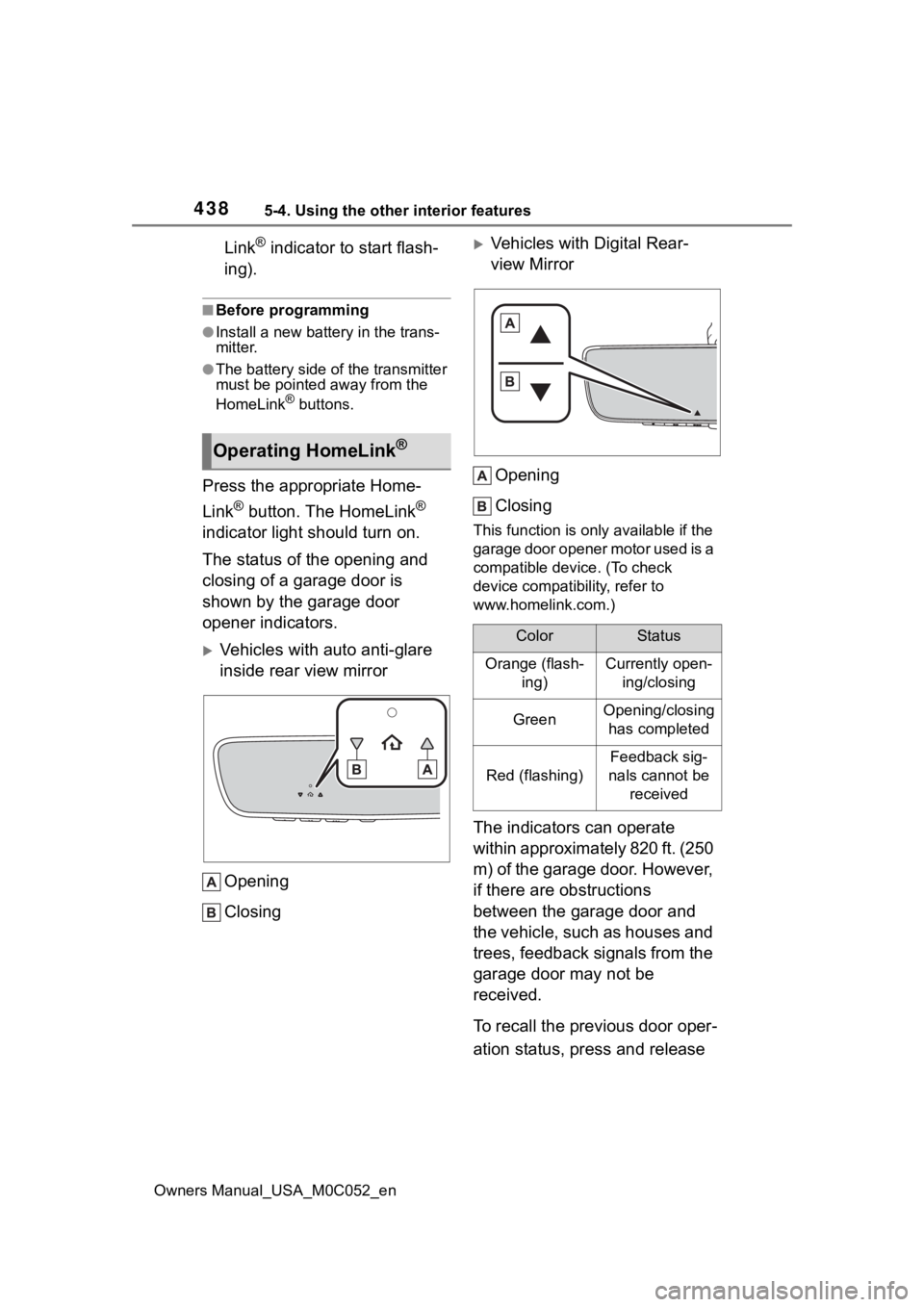
opener indicators.
Vehicles with auto anti-glare
inside rear view mirror
Opening
Closing
Vehicles with Digital Rear-
view MirrorOpening
Closing
This function is only available if the
garage door opener motor used is a
compatible device. (To check
device compatibility, refer to
www.homelink.com.)
The indicators can operate
within approximately 820 ft. (250
m) of the garage door. However,
if there are obstructions
between the garage door and
the vehicle, such as houses and
trees, feedback signals from the
garage door may not be
received.
To recall the previous door oper-
ation status, press and release
Operating HomeLink®
ColorStatus
Orange (flash- ing)Currently open-ing/closing
GreenOpening/closing has completed
Red (flashing)
Feedback sig-
nals cannot be received
Page 467 of 618

4696-3. Do-it-yourself maintenance
Owners Manual_USA_M0C052_en
6
Maintenance and care
■How to change the unit
1 Park the vehicle in a safe
place and turn the power
switch off.
Changing the unit cannot be per-
formed while the vehicle is moving.
2Turn the power switch to ON.
3 Press or of the meter
control switch to select .
4 Press or to select
“Vehicle Settings” and then
press and hold .
5 Press or to select
“TPWS” and then press .
6 Press or to select “Set
Unit” and then press .
7 Press or to select the
desired unit and then press
.
■Routine tire inflation pressure
checks
The tire pressure warning system
does not replace routine tire inflation
pressure checks. Make sure to
check tire inflation pressure as part
of your routine of daily vehicle
checks.
■Tire inflation pressure
●It may take a few minutes to dis-
play the tire inflation pressure
after the power switch is turned to
ON. It may also take a few min-
utes to display the tire inflation
pressure after inflation pressure
has been adjusted.
●Tire inflation pressure changes
with temperature. The displayed
values may also be different from
the values measured using a tire
pressure gauge.
■Situations in which the tire
pressure warning system may
not operate properly
●In the following cases, the tire
pressure warning system may not
operate properly.
• If non-genuine Toyota wheels are
used.
• A tire has been replaced with a
tire that is not an OE (Original
Equipment) tire.
• A tire has been replaced with a
tire that is not of the specified size.
• Tire chains, etc. , are equipped.
• An auxiliary-support ed run-flat tire
is equipped.
• If a window tint that affects the radio wave signals is installed.
• If there is a lot of snow or ice on
the vehicle, particularly around the
wheels or wheel housings.
• If the tire inflation pressure is
extremely higher than the speci-
fied level.
• If wheels without tire pressure
warning valves and transmitters
are used.
• If the ID code on the tire pressure
warning valves and transmitters is
not registered in the tire pressure
warning computer.
●Performance may be affected in
the following situations.
• Near a TV tower, electric power plant, gas station, radio station,
large display, airpo rt or other facil-
ity that generates strong radio
waves or electrical noise
• When carrying a portable radio,
cellular phone, cordless phone or
other wireless communication
device
If tire position info rmation is not cor-
rectly displayed due to the radio
wave conditions, the display may be
corrected by driving and changing
the radio wave c onditions may
Page 487 of 618
4896-3. Do-it-yourself maintenance
Owners Manual_USA_M0C052_en
6
Maintenance and care
tecting the wiring harness from
damage.
■When replacing light bulbs
Toyota recommends that you use
genuine Toyota products designed
for this vehicle.
Because certain bulbs are con-
nected to circuits designed to pre-
vent overload, non-genuine parts or
parts not designed for this vehicle
may be unusable.
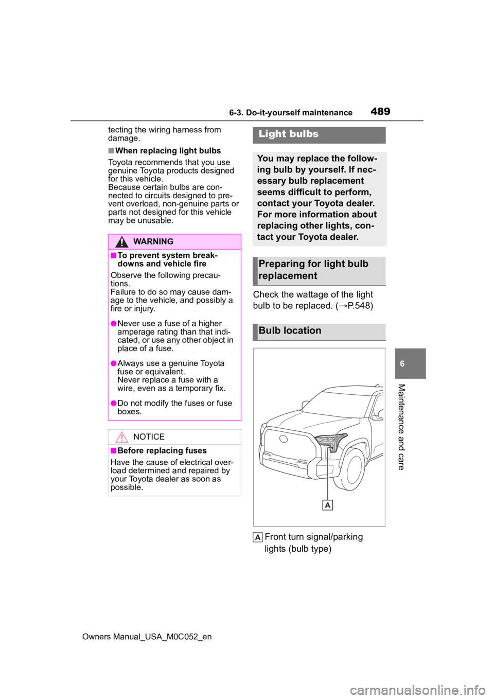
Check the wattage of the light
bulb to be replaced. ( P.548)
Front turn signal/parking
lights (bulb type)
WARNING
■To prevent system break-
downs and vehicle fire
Observe the following precau-
tions.
Failure to do so may cause dam-
age to the vehicle, and possibly a
fire or injury.
●Never use a fuse of a higher
amperage rating than that indi-
cated, or use any other object in
place of a fuse.
●Always use a genuine Toyota
fuse or equivalent.
Never replace a fuse with a
wire, even as a temporary fix.
●Do not modify the fuses or fuse
boxes.
NOTICE
■Before replacing fuses
Have the cause of electrical over-
load determined and repaired by
your Toyota dealer as soon as
possible.
Light bulbs
You may replace the follow-
ing bulb by yourself. If nec-
essary bulb replacement
seems difficult to perform,
contact your Toyota dealer.
For more information about
replacing other lights, con-
tact your Toyota dealer.
Preparing for light bulb
replacement
Bulb location
Page 488 of 618

4906-3. Do-it-yourself maintenance
Owners Manual_USA_M0C052_en
■Lights that need to be
replaced by your Toyota
dealer
Headlights
Daytime running lights
Front turn signal/parking lights
(LED type)
Front fog lights
Side marker lights
Side turn signal lights
Trailering light (if equipped)
Tail lights
Stop lights
Back-up light
Rear turn signal lights
High mounted stoplight/cargo
lamp
Trailer hitch light (if equipped)
Bed lamp (if equipped)
Auxiliary lights (if equipped)
Light bar (if equipped)
Arch molding marker lights (if
equipped)
■When replacing the light bulbs
Confirm that they are properly
engaged with the bulb base and that
there is no light leakage.
■LED Lights
The lights other th an front turn sig-
nal/parking lights (bulb type) consist
of a number of LEDs. If any of the
LEDs burn out, take your vehicle to
your Toyota dealer to have the light
replaced.
■Condensation build-up on the
inside of the lens
Temporary condensation build-up
on the inside of t he headlight lens
does not indicate a malfunction.
Contact your Toyota dealer for more
information in t he following situa-
tions:
●Large drops of water have built up
on the inside of the lens.
●Water has built up inside the
headlight.
■When replacing light bulbs
P.489
■Front turn signal/parking
lights (bulb type)
1 To allow enough working
space, turn the steering
wheel to the opposite side of
the bulb to be replaced.
Remove the screws, and
remove the fender liner.
Turn the steering wheel to the left
when replacing the right side light
bulb, and turn the steering wheel to
the right when replacing the left
side light bulb.
Replacing light bulb
Page 492 of 618
4947-1. Essential information
Owners Manual_USA_M0C052_en
7-1.Essential information
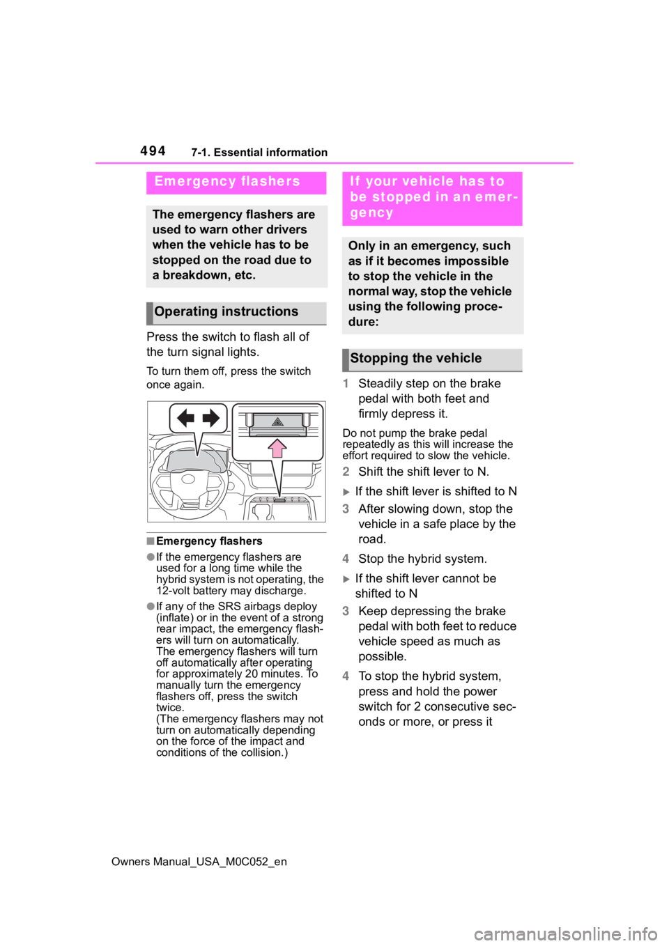
Press the switch to flash all of
the turn signal lights.
To turn them off, press the switch
once again.
■Emergency flashers
●If the emergency flashers are
used for a long time while the
hybrid system is not operating, the
12-volt battery may discharge.
●If any of the SRS airbags deploy
(inflate) or in the event of a strong
rear impact, the emergency flash-
ers will turn on automatically.
The emergency flashers will turn
off automatically after operating
for approximately 20 minutes. To
manually turn t he emergency
flashers off, press the switch
twice.
(The emergency flashers may not
turn on automatically depending
on the force of the impact and
conditions of the collision.)
1 Steadily step on the brake
pedal with both feet and
firmly depress it.
Do not pump the brake pedal
repeatedly as this will increase the
effort required to slow the vehicle.
2Shift the shift lever to N.
If the shift lever is shifted to N
3 After slowing down, stop the
vehicle in a safe place by the
road.
4 Stop the hybrid system.
If the shift lever cannot be
shifted to N
3 Keep depressing the brake
pedal with both feet to reduce
vehicle speed as much as
possible.
4 To stop the hybrid system,
press and hold the power
switch for 2 consecutive sec-
onds or more, or press it
Emergency flashers
The emergency flashers are
used to warn other drivers
when the vehicle has to be
stopped on the road due to
a breakdown, etc.
Operating instructions
If your vehicle has to
be stopped in an emer-
gency
Only in an emergency, such
as if it becomes impossible
to stop the vehicle in the
normal way, stop the vehicle
using the following proce-
dure:
Stopping the vehicle