Page 403 of 618
4055-1. Using the air conditioning system and defogger
Owners Manual_USA_M0C052_en
5
Interior features
To turn on the “SYNC” mode,
operate the “SYNC” toggle
upwards or downwards.
The driver’s side temperature con-
trol toggle can be used to adjust the
temperature for the driver’s and
front passenger’s side. To enter
individual mode, operate the front
passenger’s side temperature con-
trol toggle or press the “SYNC” tog-
gle again.
When the “SYNC” mode is on, the
“SYNC” indicator is illuminate.
This feature is used to prevent
ice from building up on the wind-
shield and wiper blades.
Press the rear window and out-
side rear view mirror defoggers
switch.
The windshield wiper de-icer will
automatically turn off after 15 min-
utes.
Turning the rear window and out-
side rear view mirror defoggers on
will turn the windshield wiper de-
icer on.
When the rear window and outside
rear view mirror defoggers switch is
on, the indicator illuminates on the
rear window and ou tside rear view
mirror defoggers switch.
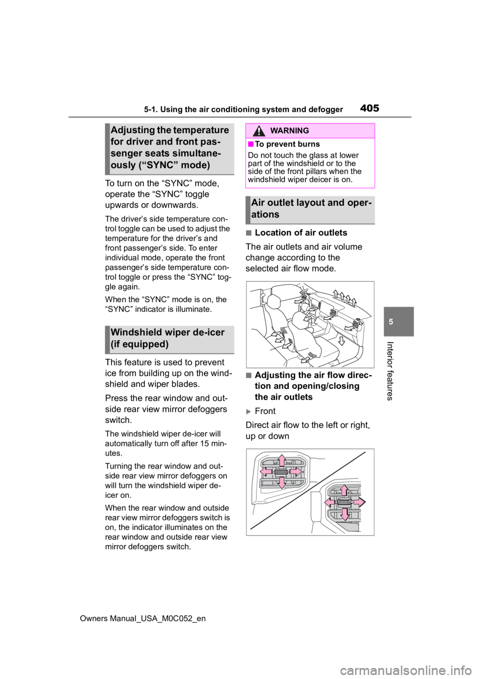
■Location of air outlets
The air outlets and air volume
change according to the
selected air flow mode.
■Adjusting the air flow direc-
tion and opening/closing
the air outlets
Front
Direct air flow to the left or right,
up or down
Adjusting the temperature
for driver and front pas-
senger seats simultane-
ously (“SYNC” mode)
Windshield wiper de-icer
(if equipped)
WARNING
■To prevent burns
Do not touch the glass at lower
part of the windshield or to the
side of the front p illars when the
windshield wiper deicer is on.
Air outlet layout and oper-
ations
Page 404 of 618
4065-1. Using the air conditioning system and defogger
Owners Manual_USA_M0C052_en
1Open the vent
2 Close the vent
Rear
Direct air flow to the left or right,
up or down
1 Open the vent
2 Close the vent
WARNING
■To not interrupt the wind-
shield defogger from operat-
ing
Do not place anything on the
instrument panel which may cover
the air outlets. Otherwise, air flow
may be obstructed, preventing the
windshield defoggers from defog-
ging.
Page 405 of 618
4075-1. Using the air conditioning system and defogger
Owners Manual_USA_M0C052_en
5
Interior features
*: If equipped
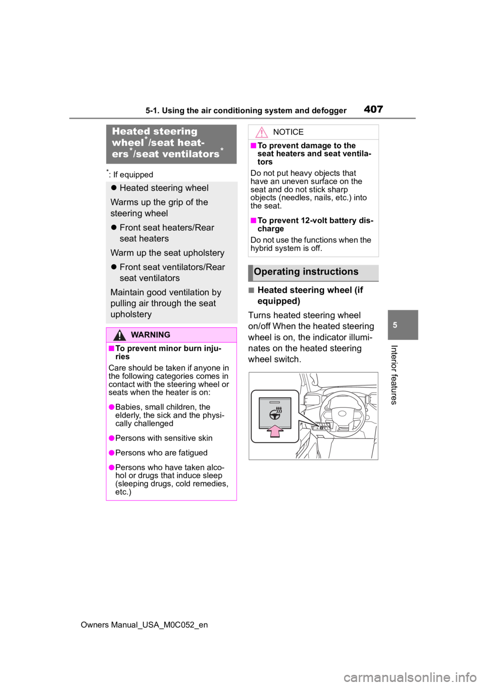
■Heated steering wheel (if
equipped)
Turns heated steering wheel
on/off When the heated steering
wheel is on, the indicator illumi-
nates on the heated steering
wheel switch.
Heated steering
wheel*/seat heat-
ers*/seat ventilators*
Heated steering wheel
Warms up the grip of the
steering wheel
Front seat heaters/Rear
seat heaters
Warm up the seat upholstery
Front seat ventilators/Rear
seat ventilators
Maintain good ventilation by
pulling air through the seat
upholstery
WARNING
■To prevent minor burn inju-
ries
Care should be taken if anyone in
the following categories comes in
contact with the steering wheel or
seats when the heater is on:
●Babies, small children, the
elderly, the sick and the physi-
cally challenged
●Persons with sensitive skin
●Persons who are fatigued
●Persons who have taken alco-
hol or drugs that induce sleep
(sleeping drugs, cold remedies,
etc.)
NOTICE
■To prevent damage to the
seat heaters and seat ventila-
tors
Do not put heavy objects that
have an uneven surface on the
seat and do not stick sharp
objects (needles, nails, etc.) into
the seat.
■To prevent 12-volt battery dis-
charge
Do not use the functions when the
hybrid system is off.
Operating instructions
Page 406 of 618
4085-1. Using the air conditioning system and defogger
Owners Manual_USA_M0C052_en
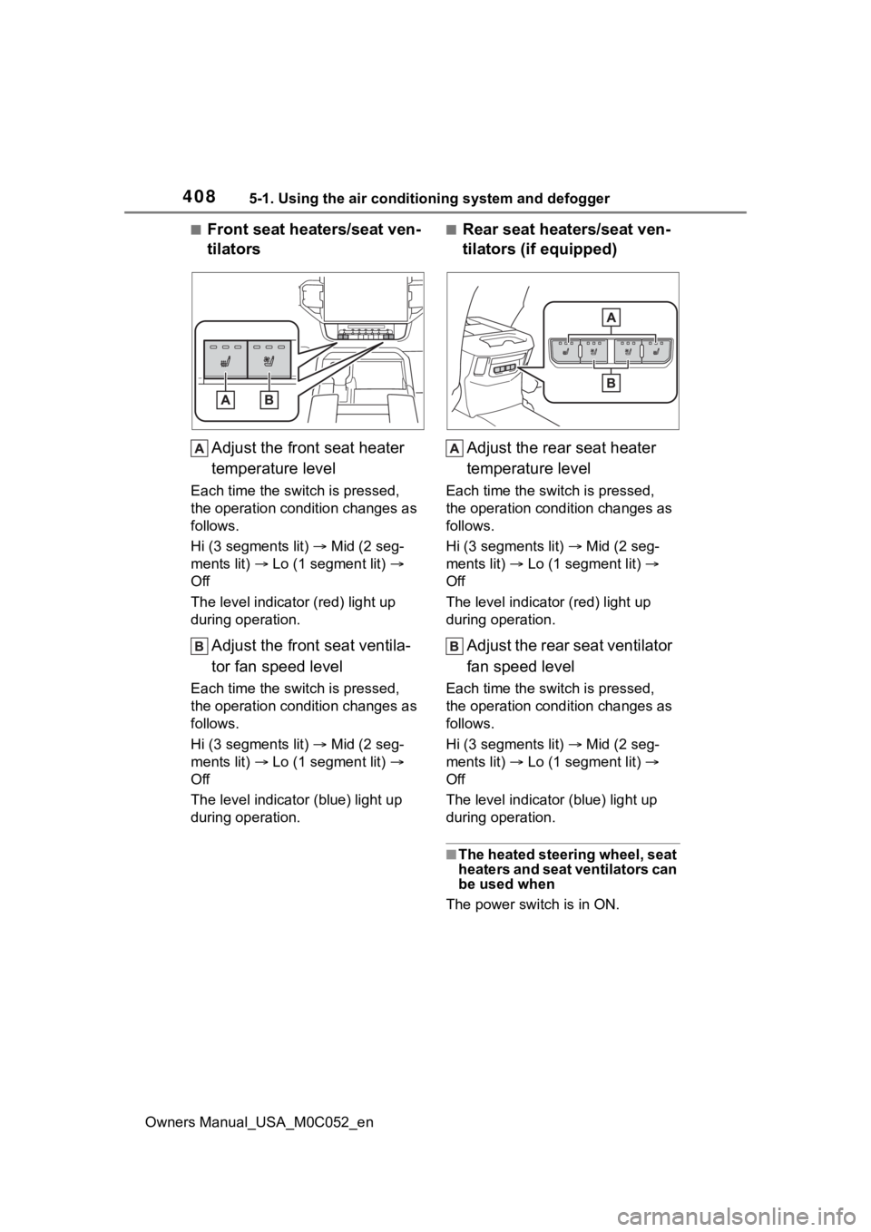
■Front seat heaters/seat ven-
tilatorsAdjust the front seat heater
temperature level
Each time the switch is pressed,
the operation condition changes as
follows.
Hi (3 segments lit) Mid (2 seg-
ments lit) Lo (1 segment lit)
Off
The level indicato r (red) light up
during operation.
Adjust the front seat ventila-
tor fan speed level
Each time the switch is pressed,
the operation condition changes as
follows.
Hi (3 segments lit) Mid (2 seg-
ments lit) Lo (1 segment lit)
Off
The level indicator (blue) light up
during operation.
■Rear seat heaters/seat ven-
tilators (if equipped)
Adjust the rear seat heater
temperature level
Each time the switch is pressed,
the operation condition changes as
follows.
Hi (3 segments lit) Mid (2 seg-
ments lit) Lo (1 segment lit)
Off
The level indicato r (red) light up
during operation.
Adjust the rear seat ventilator
fan speed level
Each time the switch is pressed,
the operation condition changes as
follows.
Hi (3 segments lit) Mid (2 seg-
ments lit) Lo (1 segment lit)
Off
The level indicato r (blue) light up
during operation.
■The heated steering wheel, seat
heaters and seat ventilators can
be used when
The power switch is in ON.
Page 407 of 618
4095-1. Using the air conditioning system and defogger
Owners Manual_USA_M0C052_en
5
Interior features
WARNING
■To prevent overheating and
minor burn injuries
Observe the following precautions
when using the seat heaters.
●Do not cover the seat with a
blanket or cushion when using
the seat heater.
●Do not use seat heater more
than necessary.
Page 427 of 618
4295-4. Using the other interior features
Owners Manual_USA_M0C052_en
5
Interior features
stable power supply
●Devices that require a constant
power supply from the power out-
let, such as a device with a timer.
■When the power supply func-
tion cannot be used
If the “AC120V” switch is pressed
but the switch indicator does not illu-
minate, the protection circuit may
have operated.
In this case, perform the appropriate
procedures as follows.
●Disconnect the plug of each
device from the p ower outlets,
check that the total power con-
sumption of all devices to be con-
nected to the power outlets,
reconnect the devices and then
press the “AC120V” switch again.
●Disconnect the plug of each
device from the p ower outlets,
check that the devices are not
malfunctioning, reconnect the
devices and then press the
“AC120V” switch again.
●If the temperature inside the vehi-
cle is high, such as after the vehi-
cle has been parked under the
sun, move the vehicle to a shaded
area, use the air conditioning sys-
tem to sufficiently cool the interior,
and then press the “AC120V”
switch again.
If the power outlets cannot be used
even after performing the appropri-
ate procedures above, have the
vehicle inspected by your Toyota
dealer.
●If any electrical device has mal-
functioned, park the vehicle in a
safe location and turn the
“AC120V” switch off.
●If the protection f unction activates
and power is cut, perform the fol-
lowing procedure.
1 Stop the vehicle in a safe place
and set the parking brake.
2 Ensure that the shift lever is in P
or N. 3
Check that the power consumed
by the electrical devices is within
400 W and any device has not
malfunctioned.
4 Press the “AC120V” switch.
If the inside of the vehicle is hot,
open the windows to lower the tem-
perature and turn the switch back on
once the inside of the vehicle
reaches a normal temperature. If
following the procedure above does
not restore power, have the vehicle
inspected at your Toyota dealer.
WARNING
■For safe use
Observe the following precau-
tions.
Failure to do so may lead to an
accident, resulting in death or
serious injury.
●Do not use devices such as the
following when driving:
• Devices which cannot be prop- erly secured within the vehicle.
• Devices which may distract the driver and be a hindrance to
safe driving, such as a TV, DVD
player, etc.
• Unsecured devices which gen- erate heat, such as a toaster,
microwave, electric heater, elec-
tric kettle, coffee maker, etc., as
they may cause burns or a fire
in the case of sudden braking or
an accident.
• Devices which may fall under the pedals and prevent the
brake pedal from being
depressed.
Page 429 of 618
4315-4. Using the other interior features
Owners Manual_USA_M0C052_en
5
Interior features
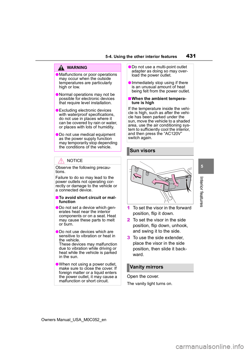
1 To set the visor in the forward
position, flip it down.
2 To set the visor in the side
position, flip down, unhook,
and swing it to the side.
3 To use the side extender,
place the visor in the side
position, then slide it back-
ward.
Open the cover.
The vanity lig ht turns on.
WARNING
●Malfunctions or poor operations
may occur when the outside
temperatures are particularly
high or low.
●Normal operations may not be
possible for electronic devices
that require level installation.
●Excluding electronic devices
with waterproof specifications,
do not use in places where it
can be covered by rain or water,
or places with lots of humidity.
●Do not use medical equipment
as the power s upply function
may temporarily stop depending
the conditions of the vehicle.
NOTICE
Observe the following precau-
tions.
Failure to do so m ay lead to the
power outlets not operating cor-
rectly or damage to the vehicle or
a connected device.
■To avoid short circuit or mal-
function
●Do not set a device which gen-
erates heat near the interior
components or on a seat. Heat
may cause these parts to melt
or burn.
●Do not use devices which are
sensitive to vibration or heat in
the vehicle.
These devices may malfunction
due to vibration while driving or
heat while the vehicle is parked
in the sun.
●When not using a power outlet,
make sure to close the cover. If
foreign matter or a liquid enters
the power outlet, it may cause a
malfunction or short circuit.
●Do not use a mul ti-point outlet
adapter as doing so may over-
load the power outlet.
●Immediately stop using if there
is an unusual amount of heat
being felt from th e power outlet.
■When the ambient tempera-
ture is high
If the temperature inside the vehi-
cle is high, such as after the vehi-
cle has been parked under the
sun, move the vehicle to a shaded
area, use the air conditioning sys-
tem to sufficiently cool the interior,
and then press the “AC120V”
switch again.
Sun visors
Vanity mirrors
Page 439 of 618
441
Owners Manual_USA_M0C052_en
6
6
Maintenance and care
Maintenance and care
6-1. Maintenance and careCleaning and protecting the vehicle exterior .......... 442
Cleaning and protecting the vehicle interior ........... 445
6-2. Maintenance Maintenance requirements.................................. 448
General maintenance.. 449
Emission inspection and maintenance (I/M) pro-
grams ........................ 452
6-3. Do-it-yourself mainte- nance
Do-it-yourself service pre- cautions ..................... 454
Hood ........................... 456
Engine compartment ... 457
12-volt battery ............. 463
Tires ............................ 466
Tire inflation pressure.. 476
Wheels ......... ...............478
Air conditioning filter .... 479
Cleaning the hybrid battery (traction battery) air intake
vents.......................... 481
Electronic key battery.. 484
Checking and replacing fuses.......................... 486
Light bulbs................... 489