2023 TOYOTA TUNDRA HYBRID height
[x] Cancel search: heightPage 148 of 618
1483-4. Adjusting the steering wheel and mirrors
Owners Manual_USA_M0C052_en
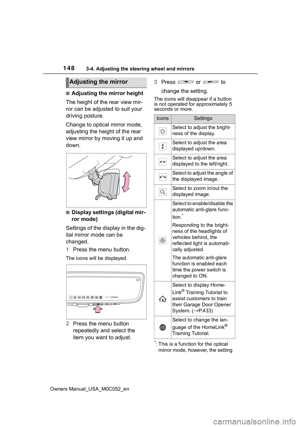
■Adjusting the mirror height
The height of the rear view mir-
ror can be adjusted to suit your
driving posture.
Change to optical mirror mode,
adjusting the height of the rear
view mirror by moving it up and
down.
■Display settings (digital mir-
ror mode)
Settings of the display in the dig-
ital mirror mode can be
changed.
1 Press the menu button.
The icons will be displayed.
2Press the menu button
repeatedly and select the
item you want to adjust. 3
Press or to
change the setting.
The icons will disappear if a button
is not operated fo r approximately 5
seconds or more.
*: This is a functi on for the optical
mirror mode, however, the setting
Adjusting the mirror
IconsSettings
Select to adjust the bright-
ness of the display.
Select to adjust the area
displayed up/down.
Select to adjust the area
displayed to the left/right.
Select to adjust the angle of
the displayed image.
Select to zoom in/out the
displayed image.
Select to enable/disable the
automatic anti-glare func-
tion.
*
Responding to the bright-
ness of the headlights of
vehicles behind, the
reflected light is automati-
cally adjusted.
The automatic anti-glare
function is enabled each
time the power switch is
changed to ON.
Select to display Home-
Link
® Training Tutorial to
assist customers to train
their Garage Door Opener
System. ( P.433)
Select to change the lan-
guage of the HomeLink
®
Training Tutorial.
Page 167 of 618
1673-5. Opening, closing the windows and moon roof
Owners Manual_USA_M0C052_en
3
Before driving
WARNING
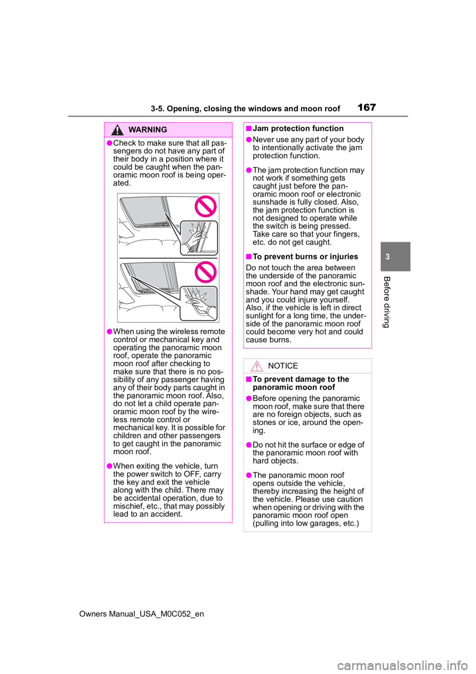
●Check to make sure that all pas-
sengers do not have any part of
their body in a position where it
could be caught when the pan-
oramic moon roof is being oper-
ated.
●When using the wireless remote
control or mechanical key and
operating the panoramic moon
roof, operate the panoramic
moon roof afte r checking to
make sure that there is no pos-
sibility of any passenger having
any of their body parts caught in
the panoramic moon roof. Also,
do not let a child operate pan-
oramic moon roof by the wire-
less remote control or
mechanical key. It is possible for
children and other passengers
to get caught in the panoramic
moon roof.
●When exiting the vehicle, turn
the power switch to OFF, carry
the key and exit the vehicle
along with the child. There may
be accidental operation, due to
mischief, etc., that may possibly
lead to an accident.
■Jam protection function
●Never use any part of your body
to intentionally activate the jam
protection function.
●The jam protection function may
not work if something gets
caught just before the pan-
oramic moon roof or electronic
sunshade is fully closed. Also,
the jam protection function is
not designed to operate while
the switch is being pressed.
Take care so that your fingers,
etc. do not get caught.
■To prevent burns or injuries
Do not touch the area between
the underside of the panoramic
moon roof and the electronic sun-
shade. Your hand may get caught
and you could injure yourself.
Also, if the vehicle is left in direct
sunlight for a long time, the under-
side of the panoramic moon roof
could become very hot and could
cause burns.
NOTICE
■To prevent damage to the
panoramic moon roof
●Before opening the panoramic
moon roof, make sure that there
are no foreign objects, such as
stones or ice, around the open-
ing.
●Do not hit the surface or edge of
the panoramic moon roof with
hard objects.
●The panoramic moon roof
opens outside the vehicle,
thereby increasing the height of
the vehicle. Please use caution
when opening or driving with the
panoramic moon roof open
(pulling into low garages, etc.)
Page 182 of 618

1824-1. Before driving
Owners Manual_USA_M0C052_en
■Trailer brake controller
P. 3 8 0
■Before towing
Check that the following conditions
are met:
●Ensure that your vehicle’s tires
are properly inflated. ( P.547)
●Trailer tires are inflated according
to the trailer manufacturer’s rec-
ommendation.
●All trailer lights work as required
by law.
●All lights work each time you con-
nect them.
●The trailer ball is set at the proper
height for the coupler on the
trailer.
●The trailer is level when it is
hitched. Do not dri ve if the trailer
is not level, and check for
improper tongue weight, overload-
ing, worn suspension, or other
possible causes.
●The trailer cargo is securely
loaded.
●The rear view mirrors conform to
all applicable federal, state/provin-
cial or local regu lations. If they do
not, install rear view mirrors
appropriate for towing purposes.
Contact your Toyota dealer for
further information about addi-
tional requirements such as a
towing kit, etc.WARNING
■Trailer towing precautions
To tow a traile r safely, use
extreme care and drive the vehi-
cle in accordance with the trailer’s
characteristics and operating con-
ditions. Failure to do so could
cause an accident resulting in
death or serious injury. Vehicle
stability and brak ing performance
are affected by trailer stability,
brake setting and performance,
and the hitch. Your vehicle will
handle differently when towing a
trailer.
■To avoid accident or injury
●Do not exceed the TWR,
unbraked TWR, GCWR, GVWR
or GAWR.
●If the gross trailer weight is over
2000 lb. (900 kg), a sway con-
trol device with sufficient capac-
ity is required.
●If the gross trailer weight is over
5000 lb. (2200 kg), a weight dis-
tributing hitch with sufficient
capacity is required.
●Adjust the tongue weight within
the appropriate range. Place
heavier loads as close to the
trailer axle as possible.
●Do not exceed 65 mph (104
km/h), the posted towing speed
limit or the spee d limit for your
trailer as set forth in your trailer
owner’s manual, whichever is
lowest. Slow down sufficiently
before making a turn, in cross
winds, on wet or slippery sur-
face, etc., to hel p avoid an acci-
dent. If you experience a
vehicle-trailer instability from
reducing a certain speed, slow
down and make sure you keep
your vehicle speed under the
speed of which you experience
the instability.
Page 187 of 618
1874-1. Before driving
Owners Manual_USA_M0C052_en
4
Driving
A recommended tongue
weight or kingpin weight var-
ies in accordance with the
types of trailers or towing as
described below.
To ensure the recommended
values shown below, the
trailer must be loaded by
referring to the following
instructions.
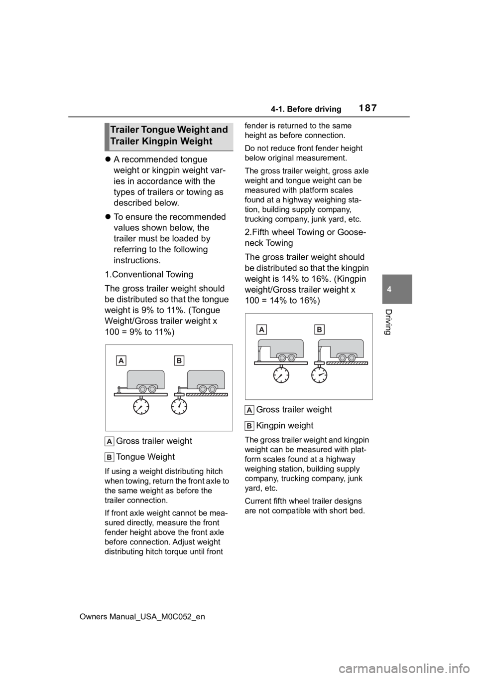
1.Conventional Towing
The gross trailer weight should
be distributed so that the tongue
weight is 9% to 11%. (Tongue
Weight/Gross trailer weight x
100 = 9% to 11%)
Gross trailer weight
Tongue Weight
If using a weight d istributing hitch
when towing, return the front axle to
the same weight as before the
trailer connection.
If front axle weight cannot be mea-
sured directly, measure the front
fender height above the front axle
before connection. Adjust weight
distributing hitch torque until front fender is returned to the same
height as before connection.
Do not reduce front fender height
below original measurement.
The gross trailer weight, gross axle
weight and tongue weight can be
measured with platform scales
found at a highway weighing sta-
tion, building supply company,
trucking company, junk yard, etc.
2.Fifth wheel Towing or Goose-
neck Towing
The gross trailer weight should
be distributed so that the kingpin
weight is 14% to 16%. (Kingpin
weight/Gross trailer weight x
100 = 14% to 16%)
Gross trailer weight
Kingpin weight
The gross trailer weight and kingpin
weight can be measured with plat-
form scales found at a highway
weighing station, building supply
company, trucking company, junk
yard, etc.
Current fifth whee l trailer designs
are not compatible with short bed.
Trailer Tongue Weight and
Trailer Kingpin Weight
Page 189 of 618
1894-1. Before driving
Owners Manual_USA_M0C052_en
4
Driving
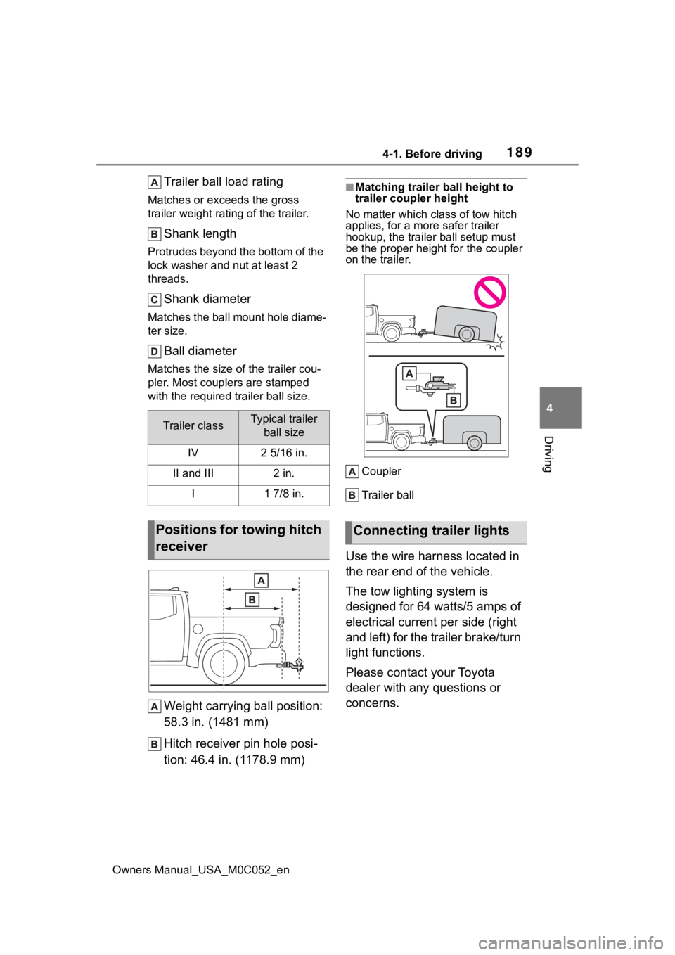
Trailer ball load rating
Matches or exceeds the gross
trailer weight rat ing of the trailer.
Shank length
Protrudes beyond the bottom of the
lock washer and nut at least 2
threads.
Shank diameter
Matches the ball mount hole diame-
ter size.
Ball diameter
Matches the size of the trailer cou-
pler. Most couplers are stamped
with the required tr ailer ball size.
Weight carrying ball position:
58.3 in. (1481 mm)
Hitch receiver pin hole posi-
tion: 46.4 in. (1178.9 mm)
■Matching trailer ball height to
trailer coupler height
No matter wh ich class of tow hitch
applies, for a mor e safer trailer
hookup, the trailer ball setup must
be the proper height for the coupler
on the trailer.
Coupler
Trailer ball
Use the wire harness located in
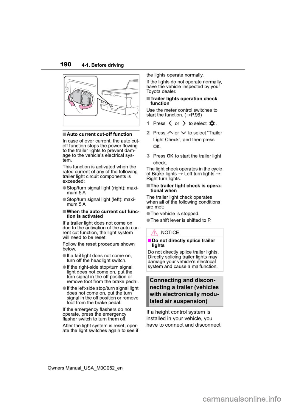
the rear end of the vehicle.
The tow lighting system is
designed for 64 watts/5 amps of
electrical current per side (right
and left) for the trailer brake/turn
light functions.
Please contact your Toyota
dealer with any questions or
concerns.
Trailer classTypical trailer ball size
IV2 5/16 in.
II and III2 in.
I1 7/8 in.
Positions for towing hitch
receiverConnecting trailer lights
Page 190 of 618
1904-1. Before driving
Owners Manual_USA_M0C052_en
■Auto current cut-off function
In case of over current, the auto cut-
off function stops the power flowing
to the trailer lights to prevent dam-
age to the vehicle’s electrical sys-
tem.
This function is activated when the
rated current of any of the following
trailer light circuit components is
exceeded:
●Stop/turn signal light (right): maxi-
mum 5 A
●Stop/turn signal light (left): maxi-
mum 5 A
■When the auto current cut func-
tion is activated
If a trailer light d oes not come on
due to the activation of the auto cur-
rent cut function , the light system
will need to be reset.
Follow the reset procedure shown
below.
●If a tail light doe s not come on,
turn off the headlight switch.
●If the right-side stop/turn signal
light does not com e on, put the
turn signal in the off position or
remove foot from t he brake pedal.
●If the left-side stop/turn signal light
does not come on, put the turn
signal in the off position or remove
foot from the brake pedal.
If the emergency flashers do not
operate, press the emergency
flasher switch to turn them off.
After the light syst em is reset, oper-
ate the light switches again to see if the lights operate normally.
If the lights do not operate normally,
have the vehicle inspected by your
Toyota dealer.
■Trailer lights operation check
function
Use the meter control switches to
start the function. ( P. 9 6 )
1 Press or to select .
2 Press or to select “Trailer
Light Check”, and then press
.
3 Press to start the trailer light
check.
The light check operates in the cycle
of Brake lights Left turn lights
Right turn lights.
■The trailer light check is opera-
tional when
The trailer light check operates
when all of the fo llowing conditions
are met:
●The vehicle is stopped.
●The shift lever is shifted to P.
If a height control system is
installed in your vehicle, you
have to connect and disconnect
NOTICE
■Do not directly splice trailer
lights
Do not directly splice trailer lights.
Directly splicing trailer lights may
damage your vehicle’s electrical
system and cause a malfunction.
Connecting and discon-
necting a trailer (vehicles
with electronically modu-
lated air suspension)
Page 191 of 618
1914-1. Before driving
Owners Manual_USA_M0C052_en
4
Driving
your trailer more carefully.
Connecting
1 Set the height control of elec-
tronically modulated air sus-
pension system to “N” mode.
2 Turn off the hybrid system, or
set the electronically modu-
lated air suspension system
to manual mode. ( P.355)
3 Connect the trailer.
4 Restart the hybrid system.
5 Press the height control
mode select switch to cancel
the manual mode condition
that was set on step 2.
6 Check that the “MAN.” indica-
tor turns off. Set the height
control of electronically mod-
ulated air suspension sys-
tem to “N” mode.
Disconnecting
1 Set the height control of elec-
tronically modulated air sus-
pension system to “N” mode.
2 Set the electronically modu-
lated air suspension system
to manual mode.
3 Turn off the hybrid system.
4 Set the supporting leg of the
trailer on the ground and
raise the hitch by 4 in. (100
mm).
5 Restart the hybrid system.
6 Press the height control
mode select switch to cancel
the manual mode condition that was set on step
2.
Check that the “MAN.” indica-
tor turns off.
7 Wait until vehicle height is
stabilized.
8 Make sure the hitch is dis-
connected. If the hitch does
not disconnect, raise the
hitch higher and repeat steps
2 through 7. Move the vehi-
cle forward in “LO” mode
where the hitch does not
touch anything in “N” mode.
Set the height control of elec-
tronically modulated air sus-
pension system to “N” mode.
Your vehicle will handle differ-
ently when towing a trailer. To
help avoid an accident, death or
serious injury, keep the following
in mind when towing:
Speed limits for towing a
trailer vary by state or prov-
ince. Do not exceed the
posted towing speed limit.
Toyota recommends that the
vehicle-trailer speed limit is 65
mph (104 km/h) on a flat,
straight, dry road. Do not
exceed this limit, the posted
towing speed limit or the
speed limit for your trailer as
set forth in your trailer owner’s
manual, whichever is lowest.
Instability of the towing vehi-
cle-trailer combination (trailer
Trailer towing tips
Page 234 of 618
2344-5. Using the driving support systems
Owners Manual_USA_M0C052_en
■Enabling/disabling the pre-
collision system
The pre-collision system can be
enabled/disabled on
( P.567) of the multi-informa-
tion display.
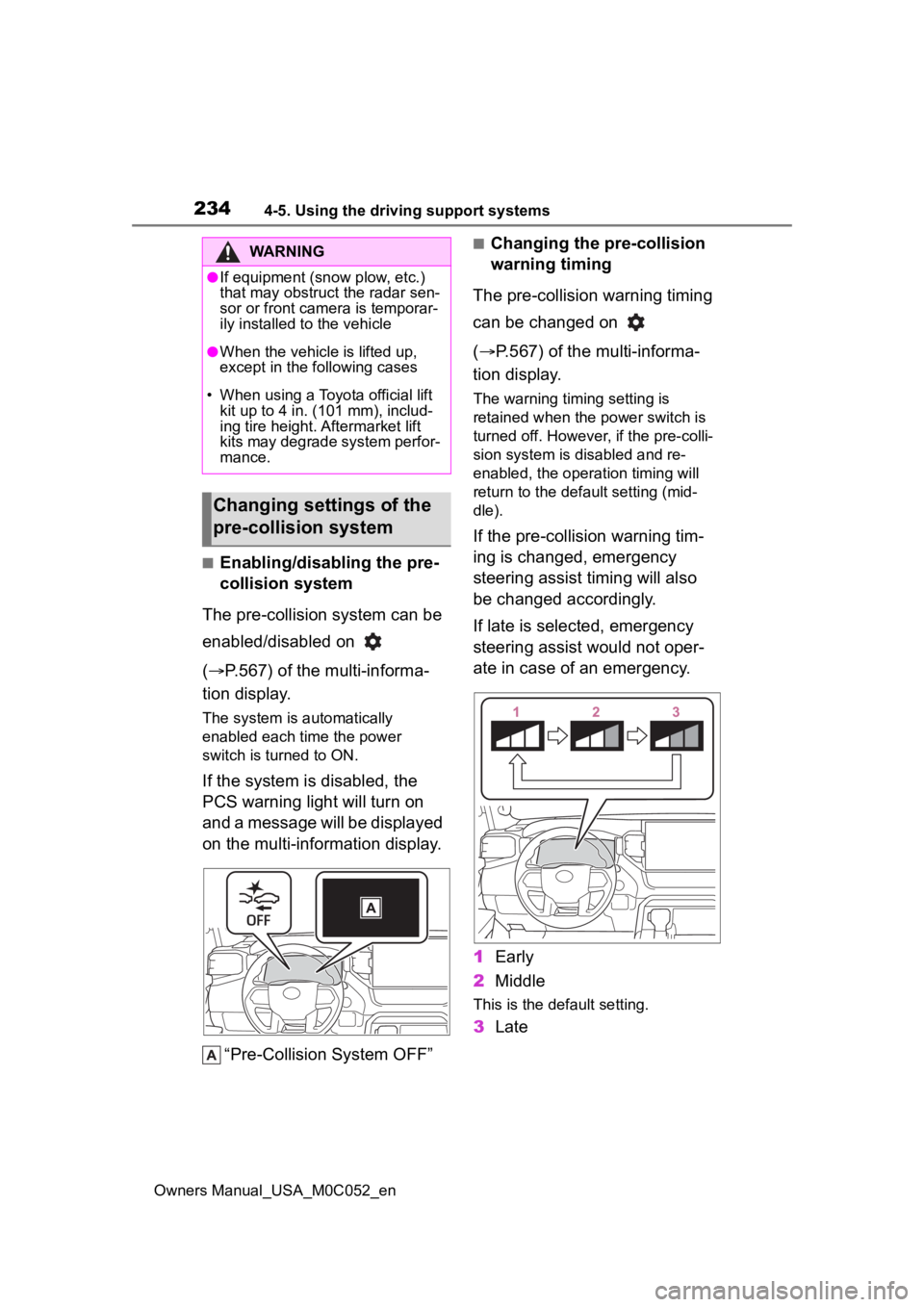
The system is a utomatically
enabled each time the power
switch is turned to ON.
If the system is disabled, the
PCS warning light will turn on
and a message will be displayed
on the multi-information display.
“Pre-Collision System OFF”
■Changing the pre-collision
warning timing
The pre-collision warning timing
can be changed on
( P.567) of the multi-informa-
tion display.
The warning timing setting is
retained when the power switch is
turned off. However, if the pre-colli-
sion system is disabled and re-
enabled, the operation timing will
return to the default setting (mid-
dle).
If the pre-collision warning tim-
ing is changed, emergency
steering assist timing will also
be changed accordingly.
If late is selected, emergency
steering assist would not oper-
ate in case of an emergency.
1 Early
2 Middle
This is the default setting.
3Late
WARNING
●If equipment (snow plow, etc.)
that may obstruct the radar sen-
sor or front camera is temporar-
ily installed to the vehicle
●When the vehicle is lifted up,
except in the following cases
• When using a Toyota official lift kit up to 4 in. (101 mm), includ-
ing tire height. Aftermarket lift
kits may degrade system perfor-
mance.
Changing settings of the
pre-collision system