2023 TOYOTA TUNDRA HYBRID ESP
[x] Cancel search: ESPPage 69 of 618

691-3. Emergency assistance
Owners Manual_USA_M0C052_en
1
For safety and security
(“SOS”)
Connects drivers to response-cen-
ter support. ( P. 7 0 )
Enhanced Roadside Assis-
tance
Provides drivers various on-road
assistance. ( P. 7 0 )
After you have signed the
Telematics Subscription Service
Agreement and are enrolled,
you can begin receiving ser-
vices.
A variety of subscription terms is
available for purchase. Contact
your Toyota dealer, call the fol-
lowing or push the “SOS” button
in your vehicle for further sub-
scription details.
The United States
1-800-331-4331
Canada
1-888-869-6828
Puerto Rico
1-877-855-8377
■Safety Connect Services Infor-
mation
●Phone calls using the vehicles
Bluetooth® technology will not be
possible during Safety Connect.
●Safety Connect is available begin-
ning Fall 2009 on select Toyota
models (in the contiguous United
States only). Contact with the
Safety Connect response center
is dependent upon the telematics
device being in operative condi- tion, cellular connection availabil-
ity, and GPS satellite signal
reception, which can limit the abil-
ity to reach the response center or
receive emergency service sup-
port. Enrollment and Telematics
Subscription Service Agreement
required. A variety of subscription
terms is available; charges vary
by subscription term selected and
location.
●Automatic Collision Notification,
Emergency Assistance and Stolen
Vehicle Location will function in
the United States, including
Hawaii and Alaska
, Puerto Rico
and in Canada, and Enhanced
Roadside Assistance will function
in the United States, Puerto Rico
and in Canada.
●Automatic Collision Notification,
Emergency Assistance, Stolen
Vehicle and Enhanced Road
Assistance will not function in the
United States Virgin Islands.
For vehicles first sold in the USVI,
no Safety Connect services will
function in and outside the United
States Virgin Islands.
●Safety Connect services are not
subject to section 255 of the Tele-
communications Act and the
device is not TTY compatible.
■Languages
The Safety Connect response cen-
ter will offer suppor t in multiple lan-
guages. The Safety Connect system
will offer voice prom pts in English,
Spanish, and French. Please indi-
cate your language of choice when
enrolling.
■When contacting the response
center
You may be unable to contact the
response center if the network is
busy.
Subscription
Page 70 of 618
701-3. Emergency assistance
Owners Manual_USA_M0C052_en
When the power switch is turned
to ON, the red indicator light
comes on for 2 seconds then
turns off. Afterward, the green
indicator light comes on, indicat-
ing that the service is active.
The following indicator light pat-
terns indicate specific system
usage conditions:
Green indicator light on =
Active service
Green indicator light flashing
= Safety Connect call in pro-
cess
Red indicator light (except at
vehicle start-up) = System
malfunction (contact your Toy-
ota dealer)
No indicator light (off) =
Safety Connect service not
active
■Automatic Collision Notifi-
cation
In case of either airbag deploy-
ment or severe rear-end colli-
sion, the system is designed to
automatically call the response
center. The responding agent
receives the vehicle’s location
and attempts to speak with the
vehicle occupants to assess the
level of emergency. If the occu- pants are unable to communi-
cate, the agent automatically
treats the call as an emergency,
contacts the nearest emer-
gency services provider to
describe the situation, and
requests that assistance be sent
to the location.
■Stolen Vehicle Location
If your vehicle is stolen, Safety
Connect can work with local
authorities to assist them in
locating and recovering the
vehicle. After filing a police
report, call the Safety Connect
response center at 1-800-331-
4331 in the United States, 1-
877-855-8377 in Puerto Rico or
1-888-869-6828 in Canada, and
follow the prompts for Safety
Connect to initiate this service.
In addition to assisting law
enforcement with recovery of a
stolen vehicle, Safety-Connect-
equipped vehicle location data
may, under certain circum-
stances, be shared with third
parties to locate your vehicle.
Further information is available
at Toyota.com.
■Emergency Assistance But-
ton (“SOS”)
In the event of an emergency on
the road, push the “SOS” button
to reach the Safety Connect
response center. The answer-
ing agent will determine your
vehicle’s location, assess the
emergency, and dispatch the
Safety Connect LED light
Indicators
Safety Connect services
Page 71 of 618

711-3. Emergency assistance
Owners Manual_USA_M0C052_en
1
For safety and security
necessary assistance required.
If you accidentally press the “SOS”
button, tell the response-center
agent that you are not experiencing
an emergency.
■Enhanced Roadside Assis-
tance
Enhanced Roadside Assistance
adds GPS data to the already
included warranty-based Toyota
roadside service.
Subscribers can press the
“SOS” button to reach a Safety
Connect response-center agent,
who can help with a wide range
of needs, such as: towing, flat
tire, fuel delivery, etc. For a
description of the Roadside
Assistance services and their
limitations, please see the
Safety Connect Terms and Con-
ditions, which are available at
Toyota.com.
Important! Read this informa-
tion about exposure to radio fre-
quency signals before using
Safety Connect;
The Safety Connect system
installed in your vehicle is a low-
power radio transmitter and
receiver. It receives and also
sends out radio frequency (RF)
signals.
In August 1996, the Federal
Communications Commission (FCC) adopted RF exposure
guidelines with safety levels for
mobile wireless phones. Those
guidelines are consistent with
the safety standards previously
set by the following U.S. and
international standards bodies.
ANSI (American National
Standards Institute) C95.1
[1992]
NCRP (National Council on
Radiation Protection and
Measurement) Report 86
[1986]
ICNIRP (International Com-
mission on Non-Ionizing Radi-
ation Protection) [1996]
Those standards were based on
comprehensive and periodic
evaluations of the relevant sci-
entific literature. Over 120 scien-
tists, engineers, and physicians
from universities, and govern-
ment health agencies and
industries reviewed the avail-
able body of research to
develop the ANSI Standard
(C95.1).
The design of Safety Connect
complies with the FCC guide-
lines in addition to those stan-
dards.
■Free /Open Source Software
Information
This product contains Free/Open
Source Software (FOSS). The
License information and/or the
source code of such FOSS can be
found at the following
Safety information for
Safety Connect
Page 92 of 618

922-1. Instrument cluster
Owners Manual_USA_M0C052_en
Engine coolant temperature gauge
Displays the engine coolant temperature
Speedometer
Displays the vehicle speed
Voltmeter
Displays the charge state
Engine oil pressure gauge
Displays the engine oil pressure
Odometer and trip meter ( P.93)
■The meters and display illumi-
nate when
The power swit ch is in ON.
■Tachometer needle feature
The tachometer needle will fade in
or out during the engine starting or
stopping, respectively.
The needle is completely visible
after the engine is turned on or
turned off.
■Clock settings screen
If clock setting item is displayed
when is selected on the multi-
information display, the system may
be malfunctioning. Have the vehicle
inspected by your Toyota dealer.
■Outside temperature display
●In the following si tuations, the cor-
rect outside tempe rature may not
be displayed, or the display may
take longer than normal to
change.
• When stopped, or driving at low
speeds (less than 12 mph [20
km/h])
• When the outside temperature
has changed suddenly (at the
entrance/exit of a garage, tunnel,
etc.)
●When “--” or “E” is displayed, the
system may be malfunctioning.
Take your vehicle to your Toyota
dealer.
●Displays the outsi de temperature
within the range of -40°F (-40°C)
to 122°F (50°C).
●When the outside temperature is
approximately 37°F (3°C) or
lower, the indicator will flash
for approximately 10 seconds,
then stay on.
■Liquid crystal display
P. 9 6
■Customization
Settings (e. g. mete r display) can be
changed on screen of the multi-
information display. ( P. 9 9 )
WARNING
■The information display at
low temperatures
Allow the interior of the vehicle to
warm up before using the liquid
crystal information display. At
extremely low temperatures, the
information disp lay monitor may
respond slowly, and display
changes may be delayed.
Page 102 of 618

1022-1. Instrument cluster
Owners Manual_USA_M0C052_en
*: If equipped
Illustrations used in this text are intended as examples, and m ay differ from
the image that is actually displayed by the he ad-up display.
Driving support system status/navigation system-linked display
area ( P.104)
Shift position display/RSA (R oad Sign Assist) (if equipped) dis -
play area ( P.200, 253)
Vehicle speed display
Hybrid System Indicator/Outside temperature display area
( P.105)
■Head-up display will operate
when
The power swit ch is in ON.
■When using the head-up dis-
play
The head-up display may seem
dark or hard to see when viewed through sunglasses, especially
polarized sunglasses. Adjust the
brightness of the head-up display or
remove your sunglasses.■Street name display
Only street names which are
included in the m ap data will be dis-
played.
Head-up display*
The head-up display projects a variety of driving-related infor -
mation and the operating state of the driving support systems
on the windshield.
System components
Page 115 of 618

1153-2. Opening, closing and locking the doors and tailgate
Owners Manual_USA_M0C052_en
3
Before driving
■If the smart key system or the
wireless remote control does
not operate properly
Use the mechanical key to lock and
unlock the doors. ( P.527)
Replace the key battery with a new
one if it is depleted. ( P.484)
■If the 12-volt battery is dis-
charged
The doors cannot be locked and
unlocked using the smart key sys-
tem or wireless remote control. Lock
or unlock the doors using the
mechanical key. ( P.527)
■Rear seat reminder function
●In order to remind you not to for-
get luggage, etc., in the rear seat,
when the power switch is turned to
OFF after any of the following con-
ditions are met, a buzzer will
sound and a message will be dis-
played on the multi-information
display for approximately 6 sec-
onds.
• The hybrid system is started within 10 minutes after opening
and closing a rear door.
• A rear door has been opened and closed after the hybrid system
was started.
However, if a rear door is opened
and then closed within approxi-
mately 2 seconds , the rear seat
reminder function may not operate.
●The rear seat reminder function
determines that luggage, etc., has
been placed in a rear seat based
on opening and closing of a rear
door. Therefore, depending on the
situation, the rear seat reminder
function may not operate and you
may still forget luggage, etc., in
the rear seat, or it may operate
unnecessarily.
●The rear seat reminder function
can be enabled/disabled.
( P.561)
■Customization
Some functions can be customized. (
P.561)
WARNING
■To prevent an accident
Observe the following precautions
while driving the vehicle.
Failure to do so may result in a
door opening and an occupant
falling out of the vehi cle, resulting
in death or serious injury.
●Ensure that all doors are prop-
erly closed and locked.
●Do not pull the inside handle of
the doors while driving.
Be especially careful for the front
doors, as the doors may be
opened even if the inside lock but-
tons are in locked position.
●Set the rear door child-protector
locks when children are seated
in the rear seats.
■When opening or closing a
door
Check the surroundings of the
vehicle such as wh ether the vehi-
cle is on an incline, whether there
is enough space for a door to
open and whether a strong wind
is blowing. When opening or clos-
ing the door, hold the door handle
tightly to prepare for any unpre-
dictable movement.
Page 123 of 618
1233-2. Opening, closing and locking the doors and tailgate
Owners Manual_USA_M0C052_en
3
Before driving
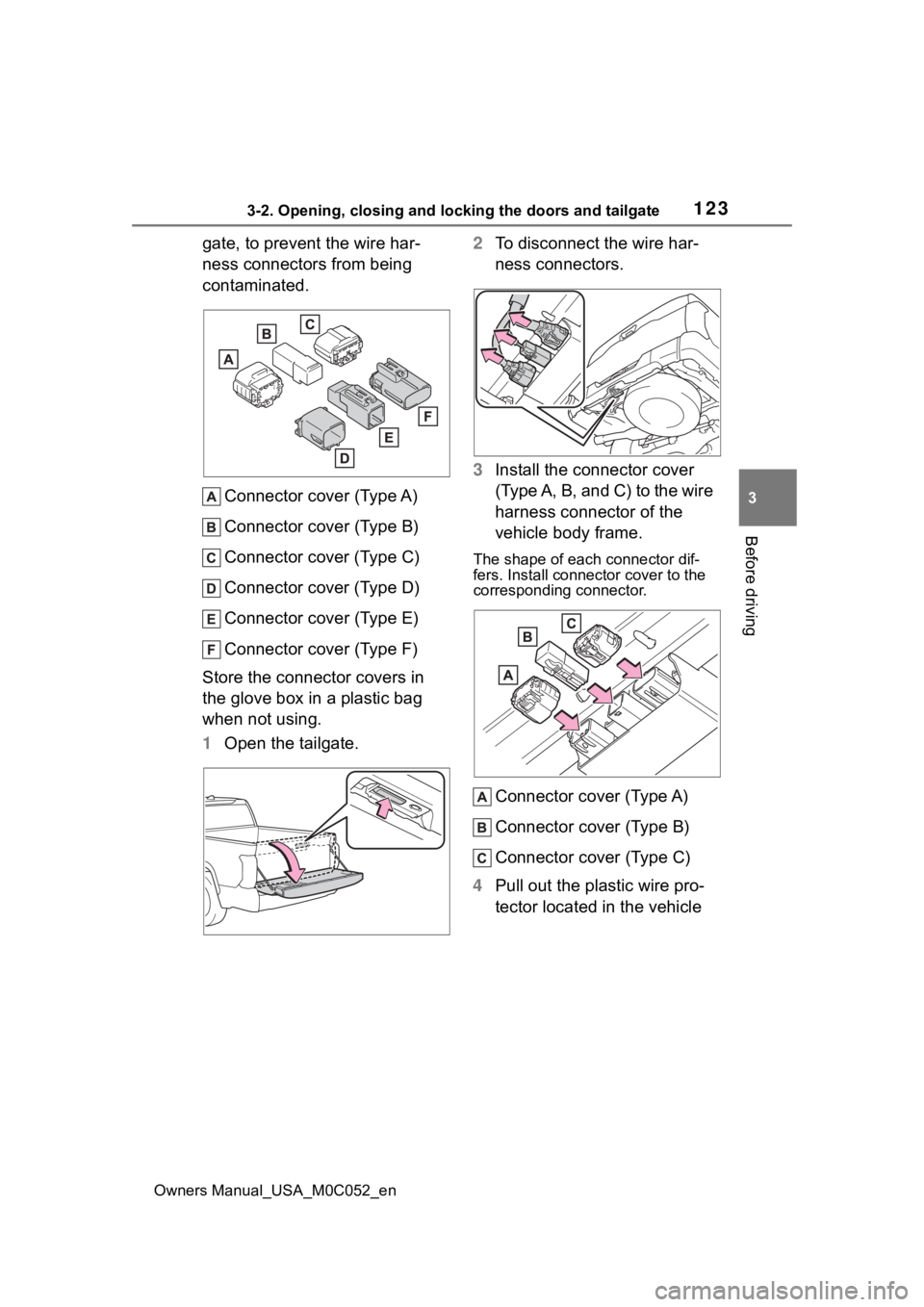
gate, to prevent the wire har-
ness connectors from being
contaminated. Connector cover (Type A)
Connector cover (Type B)
Connector cover (Type C)
Connector cover (Type D)
Connector cover (Type E)
Connector cover (Type F)
Store the connector covers in
the glove box in a plastic bag
when not using.
1 Open the tailgate. 2
To disconnect the wire har-
ness connectors.
3 Install the connector cover
(Type A, B, and C) to the wire
harness connector of the
vehicle body frame.
The shape of each connector dif-
fers. Install connec tor cover to the
corresponding connector.
Connector cover (Type A)
Connector cover (Type B)
Connector cover (Type C)
4 Pull out the plastic wire pro-
tector located in the vehicle
Page 124 of 618
1243-2. Opening, closing and locking the doors and tailgate
Owners Manual_USA_M0C052_en
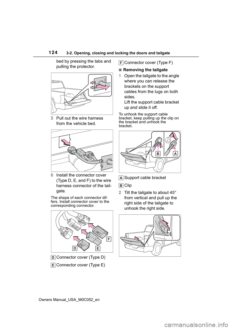
bed by pressing the tabs and
pulling the protector.
5 Pull out the wire harness
from the vehicle bed.
6 Install the connector cover
(Type D, E, and F) to the wire
harness connector of the tail-
gate.
The shape of each connector dif-
fers. Install connector cover to the
corresponding connector.
Connector cover (Type D)
Connector cover (Type E) Connector cover (Type F)
■Removing the tailgate
1 Open the tailgate to the angle
where you can release the
brackets on the support
cables from the lugs on both
sides.
Lift the support cable bracket
up and slide it off.
To unhook the support cable
bracket, keep pullin g up the clip on
the bracket and unhook the
bracket.
Support cable bracket
Clip
2 Tilt the tailgate to about 45°
from vertical and pull up the
right side of the tailgate to
unhook the right side.