2023 TOYOTA TUNDRA HYBRID brake
[x] Cancel search: brakePage 521 of 618
5237-2. Steps to take in an emergency
Owners Manual_USA_M0C052_en
7
When trouble arises
WARNING
■When the spare tire is
attached
The vehicle speed may not be
correctly detecte d, and the follow-
ing systems may not operate cor-
rectly:
• ABS & Brake assist
• VSC
• TRAC
• AUTO LSD (if equipped)
• PCS (Pre-Collision System)
• Automatic High Beam (if equipped)
• LTA (Lane Tracing Assist)
• Dynamic radar cruise control with full-speed range
• EPS
• Trailer Sway Control
• Tire pressure warning system
• BSM (Blind Spot Monitor)
• Panoramic view monitor (if equipped)
• Multi-terrain Monitor (if equipped)
• Toyota parking assist monitor (if equipped)
• Intuitive parking assist
• PKSB (Parking Support Brake)
• Navigation system (if equipped)
Also, not only can the following
system not be utilized fully, but it
may even negatively affect the
drive-train components:
• 4WD system (if equipped)
■Speed limit when using the
temporary spare tire
Do not drive at speeds in excess
of 50 mph (80 km/h) when a tem-
porary spare tire is installed on
the vehicle.
The temporary spare tire is not
designed for driving at high
speeds. Failure to observe this
precaution may lead to an acci-
dent causing death or serious
injury.
NOTICE
■Do not drive the vehicle with
a flat tire
Do not continue driving with a flat
tire.
Driving even a short distance with
a flat tire can damage the tire and
the wheel beyond repair.
■Driving with tire chains and
the temporary spare tire
Do not fit tire chains to the tempo-
rary spare tire.
Tire chains may damage the vehi-
cle body and adversely affect driv-
ing performance.
■When stowing the flat tire
Ensure that ther e is no object
caught between t he tire and the
vehicle underbody.
■When replacing the tires
When removing or fitting the
wheels, tires or th e tire pressure
warning valve and transmitter,
contact your Toyota dealer as the
tire pressure warning valve and
transmitter may be damaged if not
handled correctly.
Page 523 of 618
![TOYOTA TUNDRA HYBRID 2023 Owners Manual 5257-2. Steps to take in an emergency
Owners Manual_USA_M0C052_en
7
When trouble arises
approximately -31°F [-35°C]).
( P.195)
One of the following may be the
cause of the problem:
The 12-v TOYOTA TUNDRA HYBRID 2023 Owners Manual 5257-2. Steps to take in an emergency
Owners Manual_USA_M0C052_en
7
When trouble arises
approximately -31°F [-35°C]).
( P.195)
One of the following may be the
cause of the problem:
The 12-v](/manual-img/14/59272/w960_59272-522.png)
5257-2. Steps to take in an emergency
Owners Manual_USA_M0C052_en
7
When trouble arises
approximately -31°F [-35°C]).
( P.195)
One of the following may be the
cause of the problem:
The 12-volt battery may be
discharged. ( P.529)
The 12-volt battery terminal
connections may be loose or
corroded. ( P.463)
One of the following may be the
cause of the problem:
The 12-volt battery may be
discharged. ( P.529)
One or both of the 12-volt bat-
tery terminals may be discon-
nected. ( P.463)
Contact your Toyot a dealer if the
problem cannot be repaired, or if
repair procedures are unknown.
When the hybrid system does
not start, the following steps can
be used as an interim measure
to start the hybrid system if the
power switch is functioning nor- mally.
Do not use this starting proce-
dure except in case of emer-
gency.
1
Pull the parking brake switch
to check that the parking
brake is set. ( P.205)
Parking brake indicator will come
on.
2 Shift the shift lever to P.
3 Turn the power switch to
ACC.
4 Press and hold the power
switch for about 15 seconds
while depressing the brake
pedal firmly.
Even if the hybrid system can be
started using the above steps, the
system may be malfunctioning.
Have the vehicle inspected by your
Toyota dealer.
The interior lights and
headlights are dim, or the
horn does not sound or
sounds at a low volume.
The interior lights and
headlights do not turn on,
or the horn does not
sound.
Emergency start function
Page 526 of 618
5287-2. Steps to take in an emergency
Owners Manual_USA_M0C052_en
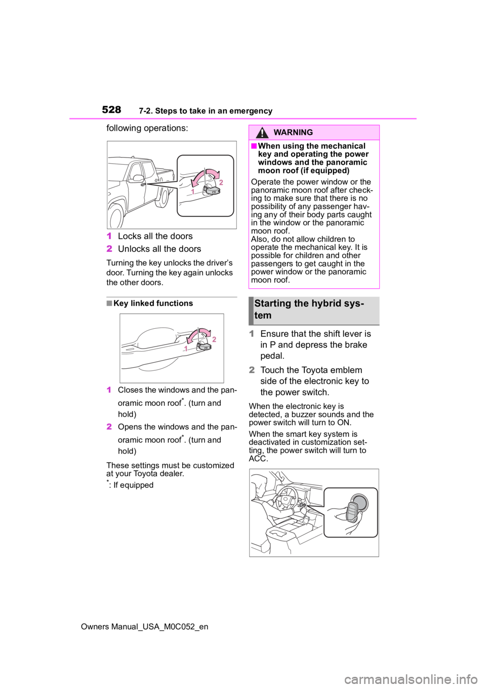
following operations:
1Locks all the doors
2 Unlocks all the doors
Turning the key unlocks the driver’s
door. Turning the key again unlocks
the other doors.
■Key linked functions
1 Closes the windows and the pan-
oramic moon roof
*. (turn and
hold)
2 Opens the windows and the pan-
oramic moon roof
*. (turn and
hold)
These settings must be customized
at your Toyota dealer.
*: If equipped
1 Ensure that the shift lever is
in P and depress the brake
pedal.
2 Touch the Toyota emblem
side of the electronic key to
the power switch.
When the electronic key is
detected, a buzzer sounds and the
power switch will turn to ON.
When the smart key system is
deactivated in customization set-
ting, the power switch will turn to
ACC.
WARNING
■When using the mechanical
key and operating the power
windows and the panoramic
moon roof (if equipped)
Operate the power window or the
panoramic moon roof after check-
ing to make sure that there is no
possibility of any passenger hav-
ing any of their body parts caught
in the window or the panoramic
moon roof.
Also, do not allo w children to
operate the mechanical key. It is
possible for children and other
passengers to get caught in the
power window or the panoramic
moon roof.
Starting the hybrid sys-
tem
Page 527 of 618
5297-2. Steps to take in an emergency
Owners Manual_USA_M0C052_en
7
When trouble arises
3 Firmly depress the brake
pedal and check that is
shown on the multi-informa-
tion display.
4 Press the power switch
shortly and firmly.
In the event that the hybrid sys-
tem still cannot be started, con-
tact your Toyota dealer.
■Stopping the hybrid system
Shift the shift lever to P, set the park-
ing brake, shift the shift lever to P
and press the power switch as you
normally do when stopping the
hybrid system.
■Electronic key battery
As the above proc edure is a tempo-
rary measure, it is recommended
that the electronic key battery be
replaced immediate ly when the bat-
tery is depleted. ( P.484)
■Alarm
Using the mechanical key to lock
the doors will not set the alarm sys-
tem. If a door is unlocked using the
mechanical key when the alarm sys-
tem is set, the alarm may be trig-
gered. ( P. 8 2 )
■Changing power switch modes
Release the brake pedal and press
the power switch in step 3 above.
The hybrid system does not start
and modes will be changed each
time the switch is pressed. ( P.198)
If you have a set of jumper (or
booster) cables and a second
vehicle with a 12-volt battery,
you can jump start your vehicle
by following the steps below.
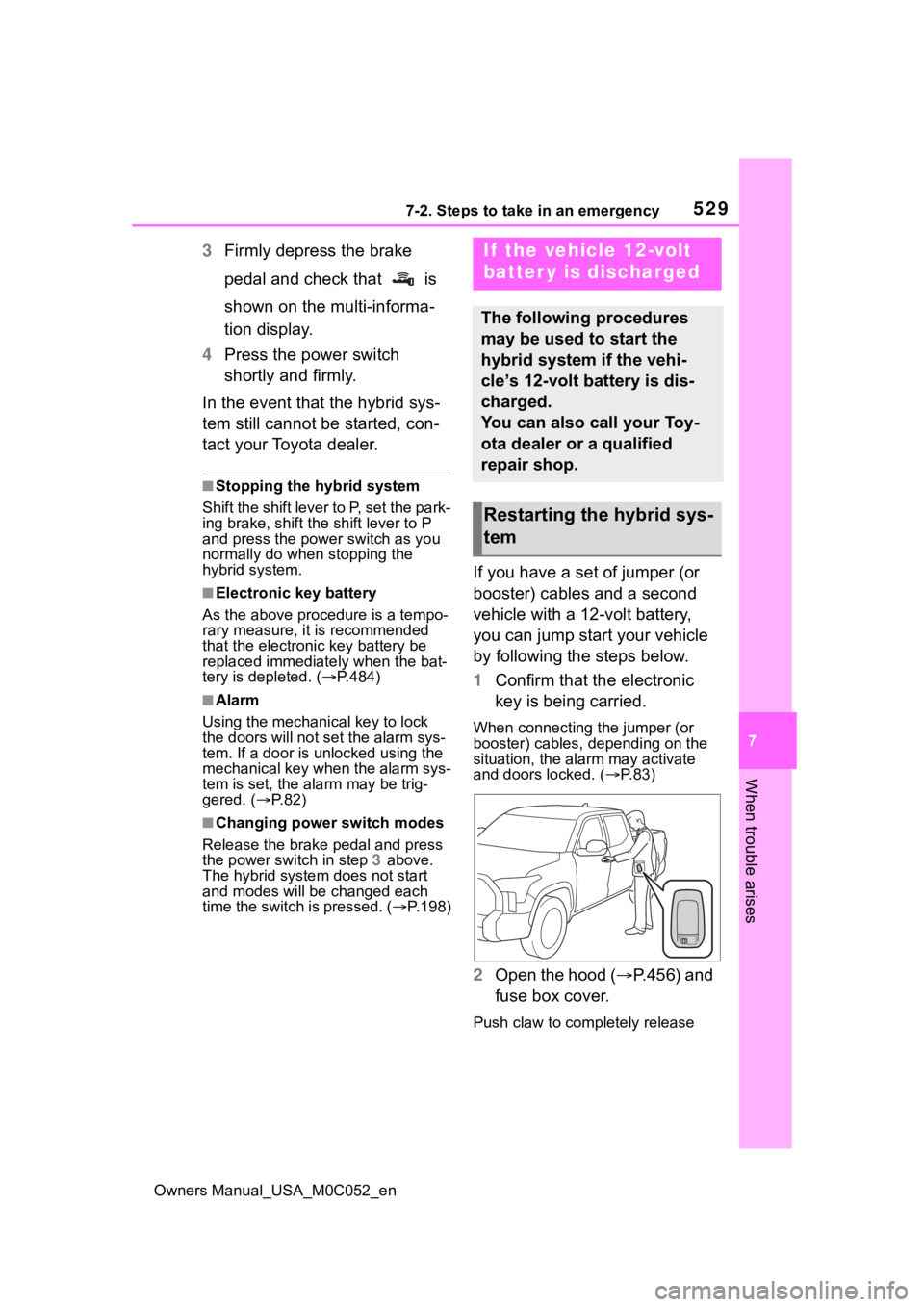
1 Confirm that the electronic
key is being carried.
When connecting the jumper (or
booster) cables, depending on the
situation, the alarm may activate
and doors locked. ( P. 8 3 )
2 Open the hood ( P.456) and
fuse box cover.
Push claw to completely release
If the vehicle 12-volt
batter y is discharged
The following procedures
may be used to start the
hybrid system if the vehi-
cle’s 12-volt battery is dis-
charged.
You can also call your Toy-
ota dealer or a qualified
repair shop.
Restarting the hybrid sys-
tem
Page 536 of 618
5387-2. Steps to take in an emergency
Owners Manual_USA_M0C052_en
1Stop the hybrid system. Set
the parking brake and shift
the shift lever to P.
2 Remove the mud, snow or
sand from around the rear
wheels.
3 Place wood, stones or some
other material under the rear
wheels to help provide trac-
tion.
4 Restart the hybrid system.
5 Shift the shift lever to D or R
and release the parking
brake. Then, while exercising
caution, depress the acceler-
ator pedal.
■When it is difficult to free the
vehicle
Try the followings.
●Turn off the TRAC
( P.375)
●Using the rear d ifferential lock*
( P.364)
●Switching the front-wheel drive
control switch* ( P.361)
●Using Crawl Control* ( P.365)
●Using Multi-te rrain Select*
( P.369)
*: If equippedIf the vehicle becomes
stuck
Carry out the following pro-
cedures if the tires spin or
the vehicle becomes stuck
in mud, dirt or snow:
Recovering procedure
WARNING
■When attempting to free a
stuck vehicle
If you choose to push the vehicle
back and forth to free it, make
sure the surrounding area is clear
to avoid striking other vehicles,
objects or people. The vehicle
may also lunge forward or lunge
back suddenly as it becomes free.
Use extreme caution.
■When shifting the shift lever
Be careful not to shift the shift
lever with the accelerator pedal
depressed.
This may lead to unexpected
rapid acceleration of the vehicle
that may cause an accident
resulting in death o r serious injury.
NOTICE
■To avoid damaging the trans-
mission and other compo-
nents
●Avoid spinning the rear wheels
and depressing the accelerator
pedal more than necessary.
●If the vehicle remains stuck
even after these procedures are
performed, the vehicle may
require towing to be freed.
Page 544 of 618
5468-1. Specifications
Owners Manual_USA_M0C052_en
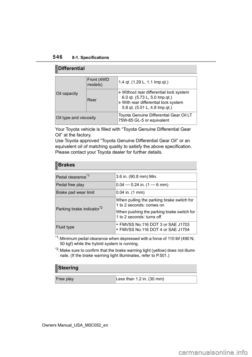
Your Toyota vehicle is filled with “Toyota Genuine Differential Gear
Oil” at the factory.
Use Toyota approved “Toyota Genuine Differential Gear Oil” or an
equivalent oil of matching quality to satisfy the above specifi cation.
Please contact your Toyota dealer for further details.
*1: Minimum pedal clearance when depressed with a force of 110 lbf (490 N,
50 kgf) while the hybrid system is running.
*2: Make sure to confirm that the brake warning light (yellow) doe s not illumi-
nate. (If the brake warning light illuminates, refer to P.501.)
Differential
Oil capacity
Front (4WD
models)1.4 qt. (1.29 L, 1.1 Imp.qt.)
Rear
Without rear differential lock system
6.0 qt. (5.73 L , 5.0 Imp.qt.)
With rear differential lock system
5.8 qt. (5.51 L, 4.8 Imp.qt.)
Oil type and viscosityToyota Genuine Differential Ge ar Oil LT
75W-85 GL-5 or equivalent
Brakes
Pedal clearance*13.6 in. (90.8 mm) Min.
Pedal free play0.04 0.24 in. (1 6 mm)
Brake pad wear limit0.04 in. (1 mm)
Parking brake indicator*2
When pulling the parking brake switch for
1 to 2 seconds: comes on
When pushing the parking brake switch for
1 to 2 seconds: turns off
Fluid typeFMVSS No.116 DOT 3 or SAE J1703
FMVSS No.116 DOT 4 or SAE J1704
Steering
Free playLess than 1.2 in. (30 mm)
Page 553 of 618
5558-1. Specifications
Owners Manual_USA_M0C052_en
8
Vehicle specifications
heat buildup and possible tire fail- ure.
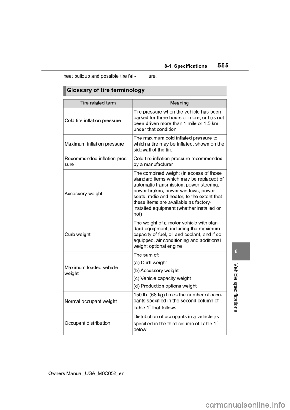
Glossary of tire terminology
Tire related termMeaning
Cold tire inflation pressure
Tire pressure when the vehicle has been
parked for three hours or more, or has not
been driven more than 1 mile or 1.5 km
under that condition
Maximum inflation pressure
The maximum cold inf lated pressure to
which a tire may be inflated, shown on the
sidewall of the tire
Recommended inflation pres-
sureCold tire inflation pressure recommended
by a manufacturer
Accessory weight
The combined weight (in excess of those
standard items which may be replaced) of
automatic transmission, power steering,
power brakes, power windows, power
seats, radio and heater, to the extent that
these items are ava ilable as factory-
installed equipment (whether installed or
not)
Curb weight
The weight of a moto r vehicle with stan-
dard equipment, including the maximum
capacity of fuel, oil and coolant, and if so
equipped, air conditioning and additional
weight optional engine
Maximum loaded vehicle
weight
The sum of:
(a) Curb weight
(b) Accessory weight
(c) Vehicle capacity weight
(d) Production options weight
Normal occupant weight
150 lb. (68 kg) times the number of occu-
pants specified in the second column of
Ta b l e 1
* that follows
Occupant distribution
Distribution of occupants in a vehicle as
specified in the third column of Table 1
*
below
Page 554 of 618
5568-1. Specifications
Owners Manual_USA_M0C052_en
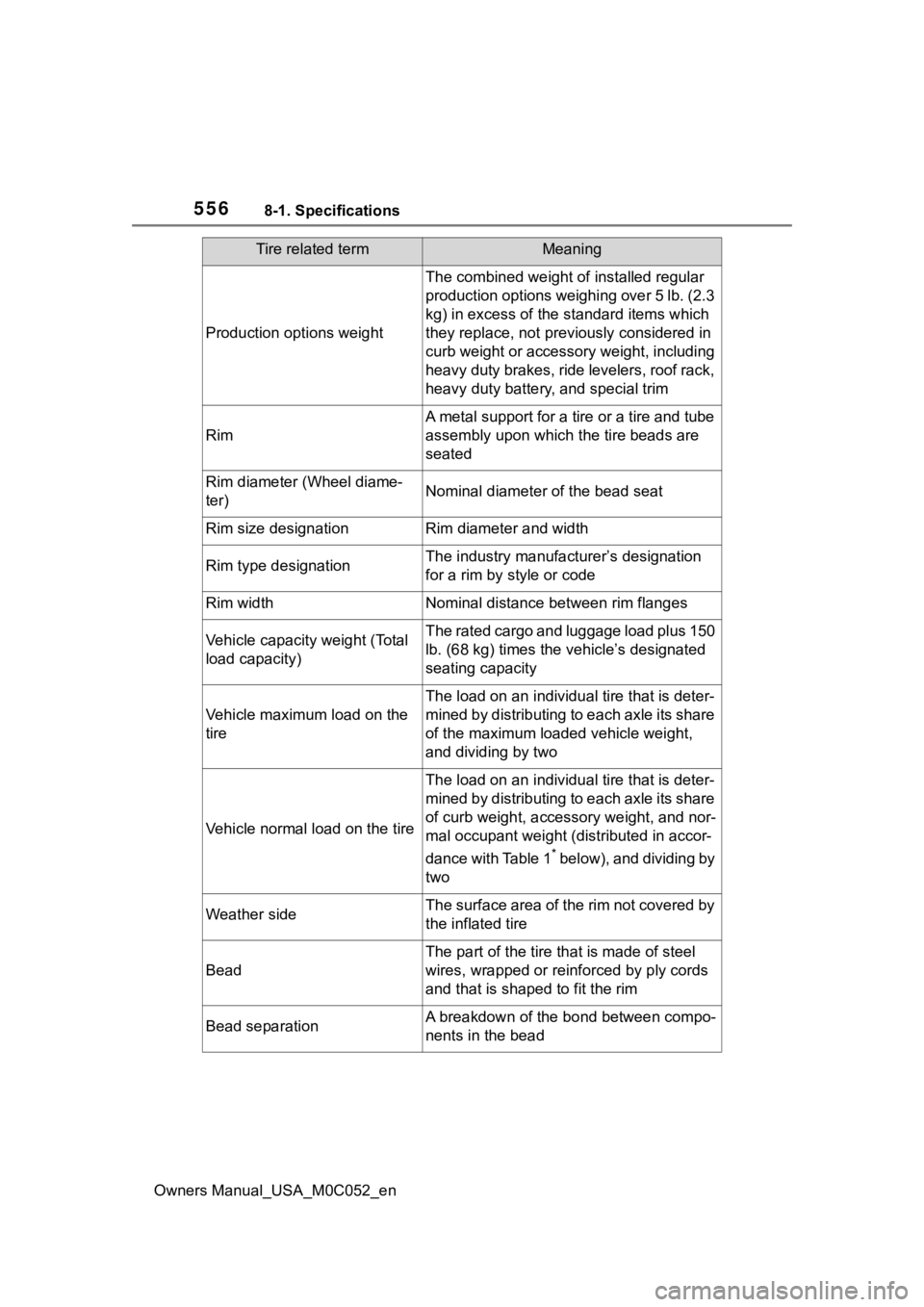
Production options weight
The combined weight of installed regular
production options weighing over 5 lb. (2.3
kg) in excess of the standard items which
they replace, not previously considered in
curb weight or accessory weight, including
heavy duty brakes, ride levelers, roof rack,
heavy duty battery, and special trim
Rim
A metal support for a tire or a tire and tube
assembly upon which the tire beads are
seated
Rim diameter (Wheel diame-
ter)Nominal diameter of the bead seat
Rim size designationRim diameter and width
Rim type designationThe industry manufacturer’s designation
for a rim by style or code
Rim widthNominal distance between rim flanges
Vehicle capacity weight (Total
load capacity)The rated cargo and luggage load plus 150
lb. (68 kg) times the vehicle’s designated
seating capacity
Vehicle maximum load on the
tire
The load on an individua l tire that is deter-
mined by distributing to each axle its share
of the maximum loaded vehicle weight,
and dividing by two
Vehicle normal load on the tire
The load on an individua l tire that is deter-
mined by distributing to each axle its share
of curb weight, accessory weight, and nor-
mal occupant weight (distributed in accor-
dance with Table 1
* below), and dividing by
two
Weather sideThe surface area of the rim not covered by
the inflated tire
Bead
The part of the tire that is made of steel
wires, wrapped or reinforced by ply cords
and that is shaped to fit the rim
Bead separationA breakdown of the bond between compo-
nents in the bead
Tire related termMeaning