2023 TOYOTA SUPRA tow
[x] Cancel search: towPage 252 of 372
2523-1. CONTROLS
The glove compartment can be
locked with an integrated key,
refer to page 86. This prevents
access to the glove compart-
ment.
After the glove compartment is
locked, the remote control can
be handed over without the inte-
grated key, for instance when
the vehicle is parked by valet
parking.
There are storage compart-
ments in the doors.Locking
Compartments in the
doors
General information
Safety information
WARNING
Breakable objects, such as glass
bottles or glasses, can break in
the event of an accident or a brak-
ing or evasive maneuver. Broken
glass can be scattered in the car's
interior. There is a risk of injury or
risk of damage to property. Do not
use any breakable objects while
driving. Only stow breakable
objects in closed storage com-
partments.
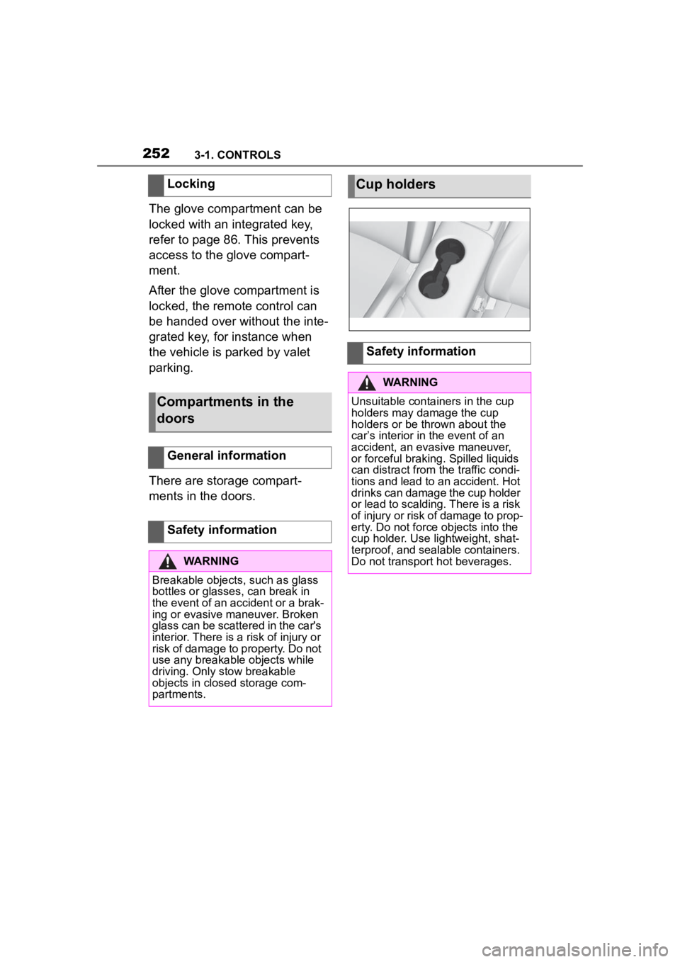
Cup holders
Safety information
WARNING
Unsuitable containers in the cup
holders may damage the cup
holders or be thrown about the
car’s interior in the event of an
accident, an evasive maneuver,
or forceful braking. Spilled liquids
can distract from the traffic condi-
tions and lead to an accident. Hot
drinks can damage the cup holder
or lead to scalding. There is a risk
of injury or risk of damage to prop-
erty. Do not force objects into the
cup holder. Use lightweight, shat-
terproof, and sealable containers.
Do not transport hot beverages.
Page 254 of 372

2543-1. CONTROLS
3Subtract the combined
weight of the driver and pas-
sengers from XXX kg or XXX
lbs.
4 The resulting figure equals
the available amount of cargo
and luggage load capacity.
For example, if the “XXX”
amount equals 1,400 lbs and
there will be five 150 lbs pas-
sengers in your vehicle, the
amount of available cargo
and luggage load capacity is
650 lbs (1,400–750 (5 x 150)
= 650 lbs).
5 Determine the combined
weight of luggage and cargo
being loaded on the vehicle.
That weight may not safely
exceed the available cargo
and luggage load capacity
calculated in Step 4.
6 If your vehicle will be towing
a trailer, load from your trailer
will be transferred to your
vehicle. Consult this manual
to determine how this
reduces the available cargo
and luggage load capacity of
your vehicle. The maximum load is the sum of
the weight of the occupants and
the cargo.
The greater the weight of the
occupants, the less cargo that
can be transported.
Cover sharp edges and cor-
ners on the cargo.
Heavy cargo: stow as far for-
ward and as low as possible,
ideally directly behind the
cargo partition.
Smaller and lighter cargo:
secure with ratchet straps or
with a cargo net or draw
straps.
Larger and heavy cargo:
secure with cargo straps.
*: if equipped
Load
Stowing and securing
cargo
Lashing eyes in the cargo
area*
Page 255 of 372
2553-1. CONTROLS
3
CONTROLS
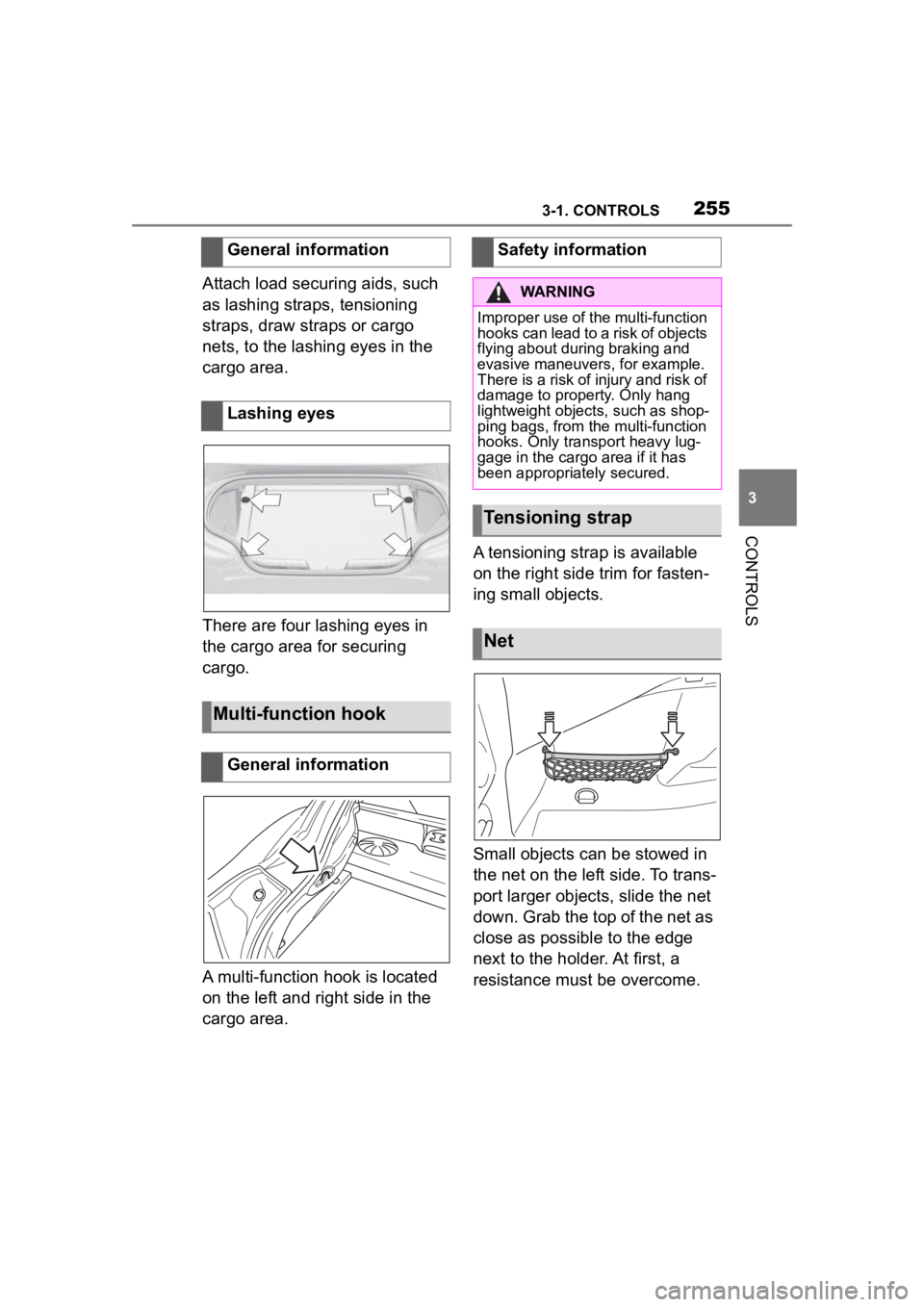
Attach load securing aids, such
as lashing straps, tensioning
straps, draw straps or cargo
nets, to the lashing eyes in the
cargo area.
There are four lashing eyes in
the cargo area for securing
cargo.
A multi-function hook is located
on the left and right side in the
cargo area.A tensioning strap is available
on the right side trim for fasten-
ing small objects.
Small objects can be stowed in
the net on the left side. To trans-
port larger objects, slide the net
down. Grab the top of the net as
close as possible to the edge
next to the holder. At first, a
resistance must be overcome.
General information
Lashing eyes
Multi-function hook
General information
Safety information
WARNING
Improper use of the multi-function
hooks can lead to a risk of objects
flying about during braking and
evasive maneuvers, for example.
There is a risk of injury and risk of
damage to property. Only hang
lightweight objects, such as shop-
ping bags, from the multi-function
hooks. Only transport heavy lug-
gage in the cargo
area if it has
been appropriately secured.
Tensioning strap
Net
Page 256 of 372

2563-1. CONTROLS
A storage compartment is avail-
able on the right side of the
cargo area.
Unlock the cover of the right
side panel, arrow 1, and fold up,
arrow 2.
The cover can be removed for
stowing bulky items.
1 Unhook the retaining straps
on the tailgate. 2
Slightly lift the cover, arrow 1,
and pull backward from the
holders, arrows 2.
To insert, proceed in reverse
order. Make sure that the lug-
gage cover is positioned cor-
rectly in the brackets.
Storage compartment on
the right side
General information
Opening
Luggage cover
Removing
Inserting
Page 262 of 372

2624-1. DRIVING TIPS
perforated brake discs can emit
functional noises. However,
functional noises have no effect
on the performance and opera-
tional reliability of the brake.
When roads are wet, salted, or
in heavy rain, gently press the
brake pedal every few miles.
Ensure that this action does not
endanger other traffic.
The heat generated during brak-
ing dries brake discs and brake
pads and protects them against
corrosion.
In this way braking efficiency will
be available when you need it.
■General information
Drive long or steep downhill gra-
dients in the gear that requires
least braking effort. Otherwise,
the brakes may overheat and
reduce brake efficiency.
You can increase the engine's
braking effect by shifting down,
going all the way to first gear, if
needed.
■Safety information
Corrosion on the brake discs
and contamination on the brake
pads are increased by the fol-
lowing circumstances:
Low mileage.
Extended periods when the
vehicle is not used at all.
Objects in the area around
the pedals
WARNING
Objects in the dri
ver's floor area
can limit the peda l distance or
block a depressed pedal. There is
a risk of an accident. Stow objects
in the vehicle such that they are
secured and cannot enter into the
driver's floor area. Use floor mats
that are suitable for the vehicle
and can be safely attached to the
floor. Do not use loose floor mats
and do not layer several floor
mats. Make sure that there is suf-
ficient clearance for the pedals.
Ensure that the floor mats are
securely fastened again after they
were removed, fo r instance for
cleaning.
Driving in wet conditions
Hills
WARNING
Light but consis tent brake pres-
sure can lead to high tempera-
tures, brakes wearing out and
possibly even brake failure. There
is a risk of an accident. Avoid
placing excessive stress on the
brake system.
WARNING
In idle state or with the engine
switched off, safety functions, for
instance engine braking effect,
braking assistance and steering
assistance, may not be available.
There is a risk of accident. Do not
attempt to drive in idle state or
with the engine switched off.
Brake disc corrosion
Page 279 of 372

2795-1. MOBILITY
5
MOBILITY
occur with low-profile tires,
which provide less cushioning
between the wheel and the
road. Be careful to avoid road
hazards and reduce your speed,
especially if your vehicle is
equipped with low-profile tires.
Indications of tire damage or
other vehicle malfunctions:
• Unusual vibrations.
• Unusual tire or running noises.
• Unusual handling such as a strong tendency to pull to the
left or right.
• Uneven wear pattern, e.g., increased wear in the area of
the tire shoulder.
Damage can be caused by the
following situations, for instance:
• Driving over curbs.
• Road damage.
• Tire inflation pressure too low.
• Vehicle overloading.
• Incorrect tire storage. Have mounting and wheel bal-
ancing carried out by your Toy-
ota dealer.
The following properties are rec-
ommended and approved by the
manufacturer of the vehicle for
the approved wheels and tires
per vehicle type and special
equipment:
• Wheel and tire combinations.
• Rim designs.
• Tire sizes.
• Tire brands.
You can ask your Toyota dealer
about the approved wheels and
tires for the vehicle and the spe-
cial equipment.
Safety information
WARNING
Damaged tires can lose tire infla-
tion pressure, which can lead to
loss of vehicle control. There is a
risk of an accident. If tire damage
is suspected while driving, imme-
diately reduce speed and stop.
Have wheels and tires checked.
For this purpose, drive carefully to
the nearest your Toyota dealer.
Have vehicle towed or trans-
ported as needed. Do not repair
damaged tires, but have them
replaced.
WARNING
Tires can become damaged by
driving over obstacles, e.g., curbs
or road damage, at high speed.
Larger wheels have a smaller tire
crosssection. The smaller the tire
cross-section, the
higher the risk
of tire damage. There is a danger
of accidents and property dam-
age. If possible, avoid driving over
objects or road conditions that
may damage tires, or drive over
them slowly and carefully.
Changing wheels and
tires
Mounting and wheel bal-
ancing
Approved wheels and tires
General information
Page 285 of 372
2855-1. MOBILITY
5
MOBILITY
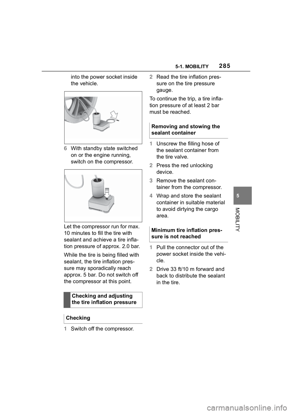
into the power socket inside
the vehicle.
6 With standby state switched
on or the engine running,
switch on the compressor.
Let the compressor run for max.
10 minutes to fill the tire with
sealant and achieve a tire infla-
tion pressure of approx. 2.0 bar.
While the tire is being filled with
sealant, the tire inflation pres-
sure may sporadically reach
approx. 5 bar. Do not switch off
the compressor at this point.
1 Switch off the compressor. 2
Read the tire inflation pres-
sure on the tire pressure
gauge.
To continue the trip, a tire infla-
tion pressure of at least 2 bar
must be reached.
1 Unscrew the filling hose of
the sealant container from
the tire valve.
2 Press the red unlocking
device.
3 Remove the sealant con-
tainer from the compressor.
4 Wrap and store the sealant
container in suitable material
to avoid dirtying the cargo
area.
1 Pull the connector out of the
power socket inside the vehi-
cle.
2 Drive 33 ft/10 m forward and
back to distribute the sealant
in the tire.
Checking and adjusting
the tire inflation pressure
Checking
Removing and stowing the
sealant container
Minimum tire inflation pres-
sure is not reached
Page 286 of 372

2865-1. MOBILITY
3Screw the connection hose of
the compressor directly onto
the tire valve stem.
4 Insert the connector into the
power socket inside the vehi-
cle.
5 With standby state switched
on or the engine running,
switch on the compressor.
If a tire inflation pressure of at least
2 bar cannot be reached, contact
your Toyota dealer.
If a tire inflation pressure of at least
2 bar is reached, see Minimum tire
inflation pressure is reached.
6Unscrew the connection
hose of the compressor from
the tire valve.
7 Pull the connector out of the
power socket inside the vehi-
cle. 8
Stow the Mobility System in
the vehicle.
1 Unscrew the connection
hose of the compressor from
the tire valve.
2 Pull the connector out of the
power socket inside the vehi-
cle.
3 Stow the Mobility System in
the vehicle.
4 Immediately drive approx. 5
miles/10 km to ensure that
the sealant is evenly distrib-
uted in the tire.
Do not exceed a speed of 50
mph/80 km/h.
If possible, do no t drive at speeds
less than 12 mph/20 km/h.
1 Stop at a suitable location.
2 Screw the connection hose of
the compressor directly onto
the tire valve stem.
Minimum tire inflation pres-
sure is reached
Adjustment