2023 TOYOTA HIGHLANDER lights
[x] Cancel search: lightsPage 353 of 552
3535-4. Using the other interior features
5
Interior features
■The wireless charger can be
operated when
The engine switch is in ACC or ON.
■Portable devices that can be
charged
●Portable devices compatible with
the Qi wireless charging standard
can be charged by the wireless
charger. However, compatibility
with all devices which meet the Qi
wireless charging standard is not
guaranteed.
●The wireless charger is designed
to supply low power electricity (5
W or less) to a cellular phone,
smartphone, or other portable
device.
●Failure to do so may result in the
possibility of fire, However, porta- ble devices, such as the following,
can be charged with more than 5
W.
• 7.5 W charging compatible iPhones can be charged at 7.5 W
or less.
• Portable devices which conform to WPC Ver 1.2.4 (Extended Power
profile ) can be charged at 10 W or
less.
■If a cover or accessory is
attached to the portable device
Do not charge a portable device if a
cover or accessory w hich is not Qi
compatible is atta ched. Depending
on the type of cover (including for
certain genuine manufacturer parts)
and/or accessory a ttached, it may
not be possible to charge the porta-
ble device. If the portable device is
placed on the charging area and
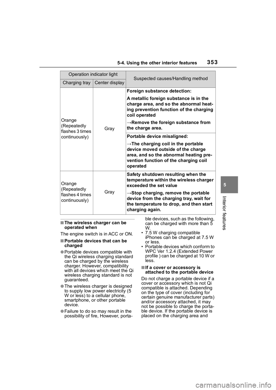
Orange
(Repeatedly
flashes 3 times
continuously)
Gray
Foreign substance detection:
A metallic foreign substance is in the
charge area, and so the abnormal heat-
ing prevention function of the charging
coil operated
→Remove the foreign substance from
the charge area.
Portable device misaligned:
→The charging coil in the portable
device moved outside of the charge
area, and so the abnormal heating pre-
vention function of the charging coil
operated
Orange
(Repeatedly
flashes 4 times
continuously)
Gray
Safety shutdown resulting when the
temperature within the wireless charger
exceeded the set value
→Stop charging, remove the portable
device from the charging tray, wait for
the temperature to drop, and then start
charging again.
Operation indicator lightSuspected causes/Handling methodCharging trayCenter display
Page 359 of 552

3595-4. Using the other interior features
5
Interior features
1To set the visor in the forward
position, flip it down.
2 To set the visor in the side
position, flip down, unhook,
and swing it to the side.
3 To use the side extender,
place the visor in the side
position, then slide it back-
ward.
Open the cover.
The light turns on when the cover is
opened.
■To prevent battery discharge
If the vanity light s remain on when
the engine switch is turned off, the
lights will go off automatically after
20 minutes.
1 Push the lid.
2 Push the lid back up half way.
■To use the overhead console
from the conversation mirror
state
Fully close the lid, then open it
again. ( P.343)
Sun visors
Vanity mirrors
NOTICE
■To prevent the battery from
being discharged
Do not leave the vanity lights on
for extended periods while the
engine is off.
Conversation mirror
Page 372 of 552
3726-1. Maintenance and care
NOTICE
• After driving in an area contami-nated with soot, oily smoke,
mine dust, iron powder or chem-
ical substances
• If the vehicle becomes heavily soiled with dust or mud
• If liquids such as benzene and gasoline are spilled on the paint
surface
●If the paint is chipped or
scratched, have it repaired
immediately.
●To prevent the wheels from cor-
roding, remove any dirt and
store in a place with low humid-
ity when storing the wheels.
■Cleaning the exterior lights
●Wash carefully. Do not use
organic substances or scrub
with a hard brush.
This may damage the surfaces
of the lights.
●Do not apply wax to the sur-
faces of the lights.
Wax may cause damage to the
lenses.
■When using an automatic car
wash (vehicles with
rain-sensing windshield wip-
ers)
Set the wiper switch to the off
position.
If the wiper switch is in “AUTO”,
the wipers may operate and the
wiper blades may be damaged.
■When using a high pressure
car wash
●When washing the vehicle, do
not spray the came ra or its sur-
rounding area directly with a
high pressure washer. Shock
applied from high pressure
water may cause the device to
not operate normally.
●Do not spray water directly on
the radar which is equipped
behind the emblem. Otherwise
it may cause the device to be
damaged.
●Do not bring the nozzle tip close
to boots (rubber or resin manu-
factured cover), connectors or
the following parts. The parts
may be damaged if they come
into contact with high-pressure
water.
• Traction related parts
• Steering parts
• Suspension parts
• Brake parts
●Keep the cleaning nozzle at
least 11.9 in. (30 cm) away from
the vehicle body. Otherwise
resin section, s uch as moldings
and bumpers, may be deformed
and damaged.
Also, do not continuously hold the
nozzle in the same place.
●Do not spray the lower part of
the windshield continuously.
If water enters the air conditioning
system intake located near the
lower part of the windshield, the
air conditioning system may not
operate correctly.
●Do not wash the underside of
the vehicle using a high pres-
sure car washer.
Page 379 of 552
3796-2. Maintenance
6
Maintenance and care
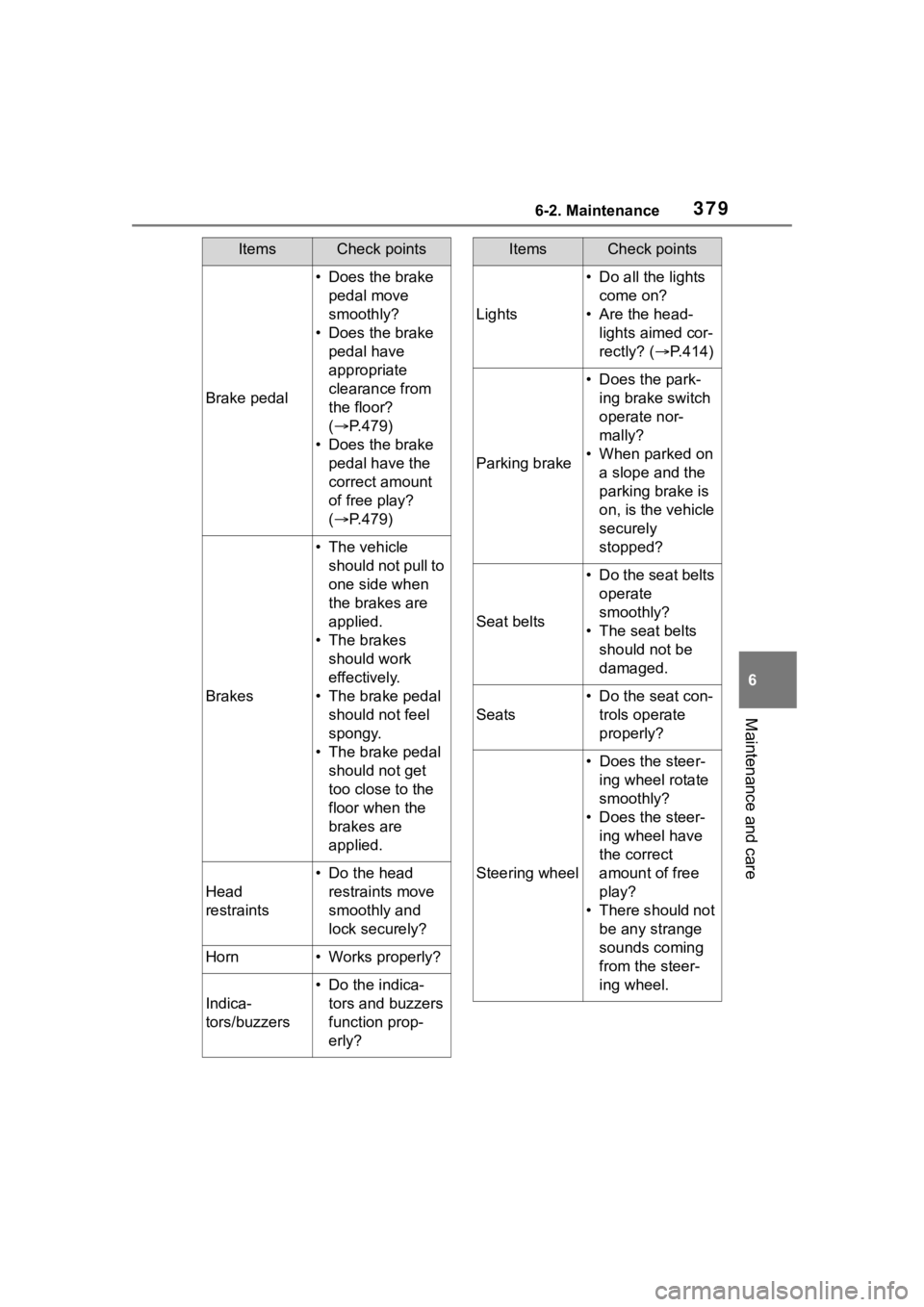
Brake pedal
• Does the brake pedal move
smoothly?
• Does the brake pedal have
appropriate
clearance from
the floor?
( P.479)
• Does the brake pedal have the
correct amount
of free play?
( P.479)
Brakes
• The vehicle
should not pull to
one side when
the brakes are
applied.
• The brakes should work
effectively.
• The brake pedal should not feel
spongy.
• The brake pedal should not get
too close to the
floor when the
brakes are
applied.
Head
restraints
• Do the head restraints move
smoothly and
lock securely?
Horn• Works properly?
Indica-
tors/buzzers
• Do the indica-tors and buzzers
function prop-
erly?
ItemsCheck points
Lights
• Do all the lights come on?
• Are the head- lights aimed cor-
rectly? (P.414)
Parking brake
• Does the park-ing brake switch
operate nor-
mally?
• When parked on a slope and the
parking brake is
on, is the vehicle
securely
stopped?
Seat belts
• Do the seat belts operate
smoothly?
• The seat belts should not be
damaged.
Seats
• Do the seat con-trols operate
properly?
Steering wheel
• Does the steer-ing wheel rotate
smoothly?
• Does the steer- ing wheel have
the correct
amount of free
play?
• There should not be any strange
sounds coming
from the steer-
ing wheel.
ItemsCheck points
Page 413 of 552

4136-3. Do-it-yourself maintenance
6
Maintenance and care
Normal fuse
Blown fuse
Type BNormal fuse
Blown fuse
Type CNormal fuse
Blown fuse
■After a fuse is replaced
●If the lights do n ot turn on even
after the fuse has been replaced,
a bulb may need replacement.
( P.415)
●If the replaced fuse blows again,
have the vehicle inspected by
your Toyota dealer.
■If there is an overload in a cir-
cuit
The fuses are designed to blow, pro-
tecting the wiring harness from
damage.
■When replacing light bulbs
Toyota recommends that you use
genuine Toyota pr oducts designed
for this vehicle. Because certain
bulbs are connected to circuits
designed to prevent overload,
non-genuine parts or parts not
designed for this vehicle may be
unusable.
WARNING
■To prevent system break-
downs and vehicle fire
Observe the following precau-
tions.
Failure to do so may cause dam-
age to the vehicle, and possibly a
fire or injury.
●Never use a fuse of a higher
amperage rating than that indi-
cated, or use any other object in
place of a fuse.
●Always use a genuine Toyota
fuse or equivalent.
Never replace a fuse with a
wire, even as a temporary fix.
●Do not modify the fuses or fuse
boxes.
NOTICE
■Before replacing fuses
Have the cause of electrical over-
load determined and repaired by
your Toyota dealer as soon as
possible.
Page 415 of 552
4156-3. Do-it-yourself maintenance
6
Maintenance and care
Check the wattage of the light
bulb to be replaced. (P.481)
P. 4 9 9
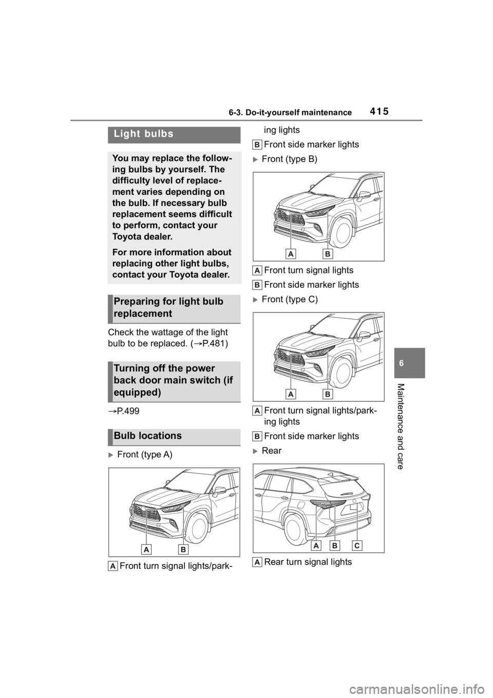
Front (type A)
Front turn signal lights/park- ing lights
Front side marker lights
Front (type B)
Front turn signal lights
Front side marker lights
Front (type C)
Front turn signal lights/park-
ing lights
Front side marker lights
RearRear turn signal lights
Light bulbs
You may replace the follow-
ing bulbs by yourself. The
difficulty level of replace-
ment varies depending on
the bulb. If necessary bulb
replacement seems difficult
to perform, contact your
Toyota dealer.
For more information about
replacing other light bulbs,
contact your Toyota dealer.
Preparing for light bulb
replacement
Turning off the power
back door main switch (if
equipped)
Bulb locations
Page 416 of 552

4166-3. Do-it-yourself maintenance
Back-up lights
License plate lights
■Lights that need to be
replaced by your Toyota
dealer
Headlight low beams
Headlight high beams
Daytime running lights (types
A and C)
Daytime running lights/park-
ing lights (type B)
Front fog lights (if equipped)
Side turn signal lights
Tail lights/stop lights
Rear side marker lights
Tail lights
High mounted stoplight
Outer foot lights (if equipped)
■LED lights
The lights other than the following
lights each consist of a number of
LEDs. If any of the LEDs burn out,
take your vehicle to your Toyota
dealer to have the light replaced.
●Front turn signal lights/parking
lights (types A and C)
●Front turn signal lights (type B)
●Front side marker lights
●Rear turn signal lights
●Back-up lights
●License plate lights
■Condensation build-up on the
inside of the lens
Temporary condensation build-up
on the inside of the light lens does
not indicate a malfunction. Contact
your Toyota dealer for more informa- tion in the following situations:
●Large drops of water have built up
on the inside of the lens.
●Water has built up
inside the light.
■When replacing light bulbs
P.413
■Front turn signal
lights/parking lights (types
A and C) and front turn sig-
nal lights (type B)
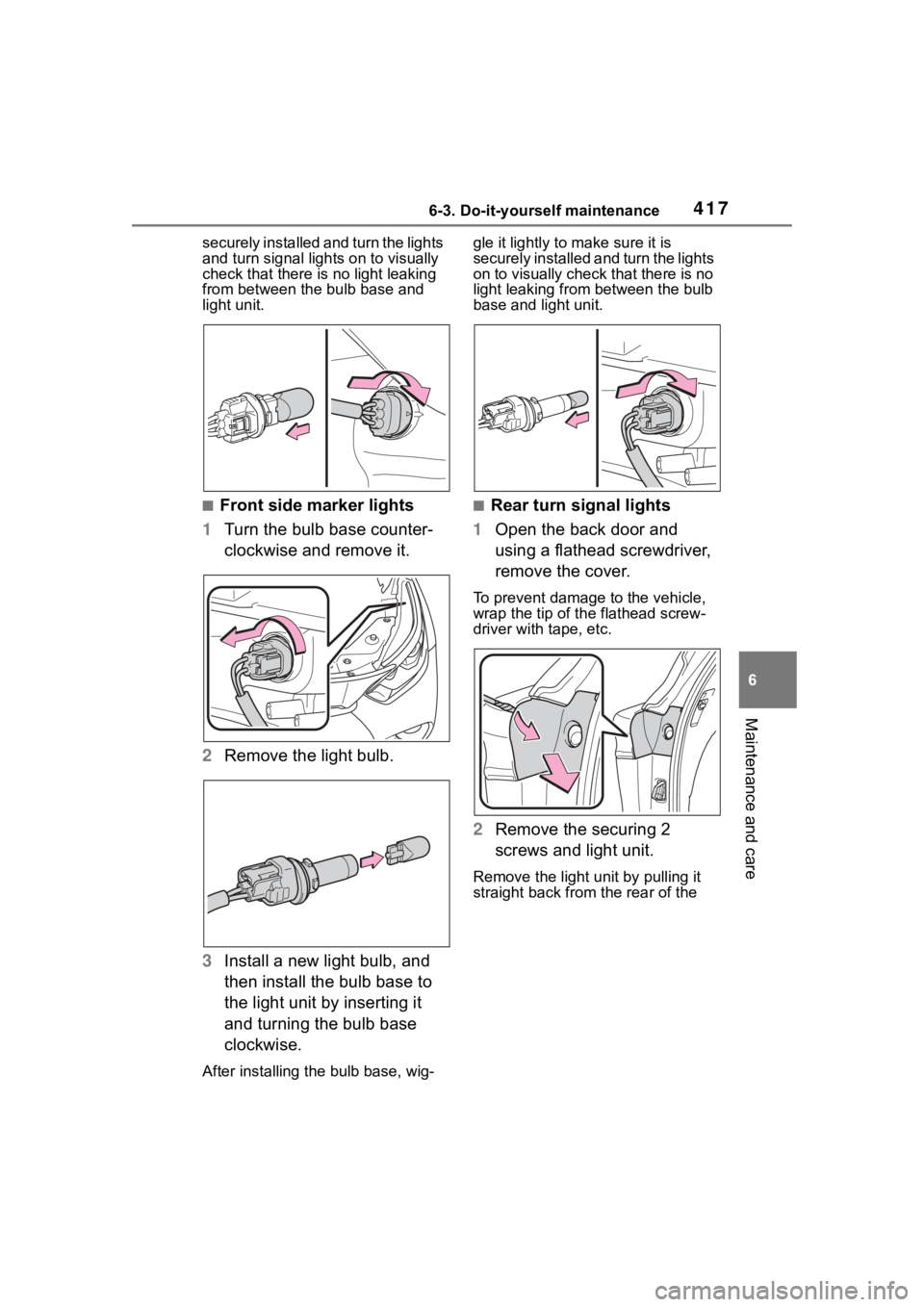
1 Turn the bulb base counter-
clockwise and remove it.
2 Remove the light bulb.
3 Install a new light bulb, and
then install the bulb base to
the light unit by inserting it
and turning the bulb base
clockwise.
After installing the bulb base, wig-
gle it lightly to make sure it is
Replacing light bulbs
Page 417 of 552
4176-3. Do-it-yourself maintenance
6
Maintenance and care
securely installed and turn the lights
and turn signal lights on to visually
check that there is no light leaking
from between the bulb base and
light unit.
■Front side marker lights
1 Turn the bulb base counter-
clockwise and remove it.
2 Remove the light bulb.
3 Install a new light bulb, and
then install the bulb base to
the light unit by inserting it
and turning the bulb base
clockwise.
After installing th e bulb base, wig- gle it lightly to make sure it is
securely installed a
nd turn the lights
on to visually check that there is no
light leaking from between the bulb
base and light unit.
■Rear turn signal lights
1 Open the back door and
using a flathead screwdriver,
remove the cover.
To prevent damage to the vehicle,
wrap the tip of th e flathead screw-
driver with tape, etc.
2 Remove the securing 2
screws and light unit.
Remove the light u nit by pulling it
straight back from the rear of the