2023 TOYOTA 86 ESP
[x] Cancel search: ESPPage 76 of 449

761-3. Emergency assistance
Connects drivers to response-cen-
ter support. (P. 7 7 )
Enhanced Roadside Assis-
tance (“i” button)
Provides drivers various on-road
assistance. ( P. 7 8 )
After you have signed the
Telematics Subscription Service
Agreement and are enrolled,
you can begin receiving ser-
vices.
A variety of subscription terms
are available for purchase. Con-
tact your Toyota dealer, call the
following appropriate Customer
Experience Center or push the
“SOS” button in your vehicle for
further subscription details.
The United States
1-800-331-4331
Canada
1-888-869-6828
■Safety Connect Services Infor-
mation
●Phone calls using the vehicle’s
Bluetooth® technology will not be
possible when Safety Connect is
active and in use.
●Safety Connect is available begin-
ning Fall 2009 on select Toyota
models (in the contiguous United
States only). Contact with the
Safety Connect response center
is dependent upon the telematics
device being in operative condi-
tion, cellular connection availabil-
ity, and GPS satellite signal
reception, which can limit the abil- ity to reach the response center or
receive emergency service sup-
port. Enrollment and Telematics
Subscription Service Agreement
are required. A variety of subscrip-
tion terms are available; charges
vary by subscription term selected
and location.
●Automatic Collision Notification,
Emergency Assistance and Stolen
Vehicle Location are available in
the United States, including
Hawaii and Alaska, and Canada,
and Enhanced Roadside Assis-
tance are available in the United
States and Canada.
●Automatic Collision Notification,
Emergency Assistance, Stolen
Vehicle and Enhanced Road
Assistance are not available in the
U.S. Virgin Islands.
For vehicles first sold in the U.S.
Virgin Islands, no Safety Connect
services will function in or outside
the U.S. Virgin Islands.
●Safety Connect services are not
subject to section
255 of the Tele-
communications Act and the
device is not TTY compatible.
■Languages
The Safety Connect response cen-
ter will offer suppor t in multiple lan-
guages. The Safety Connect system
will offer voice prompts in English
and French. Please indicate your
language of choice when enrolling.
■When contacting the response
center
You may be unable to contact the
response center if the network is
busy.
When the engine switch is
turned to “ON”, the red indicator
light and green indicator light will
Subscription
Safety Connect LED light
Indicators
Page 77 of 449

771-3. Emergency assistance
1
For safety and security
illuminate and then turn off.
Then, the green indicator light
will illuminate to indicate that the
service is active.
The following indicator light pat-
terns indicate specific system
usage conditions:
Green indicator light on =
Active service
Green indicator light flashing
= Safety Connect call in pro-
cess
Red indicator light on (except
at vehicle start-up) = System
malfunction (contact your Toy-
ota dealer)
No indicator light (off) =
Safety Connect service not
active
■Automatic Collision Notifi-
cation
In case of either airbag deploy-
ment or severe rear-end colli-
sion, the system is designed to
automatically call the response
center. The responding agent
receives the vehicle’s location
and attempts to speak with the
vehicle occupants to assess the
level of emergency. If the occu-
pants are unable to communi-
cate, the agent automatically
treats the call as an emergency,
contacts the nearest emer-
gency services provider to describe the situation, and
requests that assistance be sent
to the location.
■Stolen Vehicle Location
If your vehicle is stolen, Safety
Connect can work with local
authorities to assist them in
locating and recovering the
vehicle. After filing a police
report, call the Customer Experi-
ence Center at 1-800-331-4331
in the United States or
1-888-869-6828 in Canada, and
follow the prompts for Safety
Connect to initiate this service.
In addition to assisting law
enforcement with recovery of a
stolen vehicle, Safety-Con-
nect-equipped vehicle location
data may, under certain circum-
stances, be shared with third
parties to locate your vehicle.
Further information is available
at Toyota.com in the United
States and Toyota.ca in Canada.
■Emergency Assistance But-
ton (“SOS” button)
In the event of an emergency on
the road, push the “SOS” button
to reach the Safety Connect
response center. The answer-
ing agent will determine your
vehicle’s location, assess the
emergency, and dispatch the
necessary assistance required.
If the “SOS” button is pressed unin-
tentionally, press and hold the
“SOS” button for approximately 2
seconds or more or operate the
Safety Connect services
Page 78 of 449

781-3. Emergency assistance
connection screen on the multime-
dia system screen to cancel the
connection to a response-center
agent.
■Enhanced Roadside Assis-
tance (“i” button)
Enhanced Roadside Assistance
adds GPS data to the already
included warranty-based Toyota
roadside service.
Subscribers can press the “i”
button on the interior lights to
contact a Roadside Assistance
provider, who can help with a
wide range of needs, such as:
towing, flat tire, fuel delivery, etc.
For a description of the
Enhanced Roadside Assistance
services and their limitations,
please see the Safety Connect
Terms and Conditions, which
are available at Toyota.com in
the United States and Toyota.ca
in Canada.
If the “i” button on the interior
lights is pressed unintentionally,
press and hold the “i” button for
approximately 2 seconds or
more or operate the connection
screen on the multimedia sys-
tem screen to cancel the con-
nection to a roadside assistance
provider.
Important! Read this informa-
tion before using Safety Con- nect.
■Exposure to radio fre-
quency signals
The Safety Connect system
installed in your vehicle is a
low-power radio transmitter and
receiver. It receives and also
sends out radio frequency (RF)
signals.
In August 1996, the Federal
Communications Commission
(FCC) adopted RF exposure
guidelines with safety levels for
mobile wireless phones. Those
guidelines are consistent with
the safety standards previously
set by the following U.S. and
international standards bodies.
ANSI (American National
Standards Institute) C95.1
[1992]
NCRP (National Council on
Radiation Protection and
Measurement) Report 86
[1986]
ICNIRP (International Com-
mission on Non-Ionizing Radi-
ation Protection) [1996]
Those standards were based on
comprehensive and periodic
evaluations of the relevant sci-
entific literature. Over 120 scien-
tists, engineers, and physicians
from universities, and govern-
ment health agencies and
industries reviewed the avail-
able body of research to
develop the ANSI Standard
Safety information for
Safety Connect
Page 90 of 449
902-1. Instrument cluster
multi-information display. (P.400)
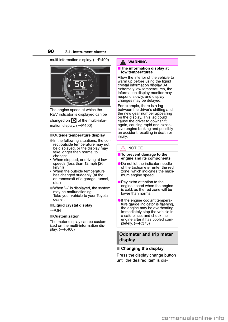
The engine speed at which the
REV indicator is d isplayed can be
changed on of the multi-infor-
mation display. ( P.400)
■Outside temperature display
●In the following si tuations, the cor-
rect outside tempe rature may not
be displayed, or the display may
take longer than normal to
change:
• When stopped, or driving at low speeds (less than 12 mph [20
km/h])
• When the outside temperature has changed suddenly (at the
entrance/exit of a garage, tunnel,
etc.)
●When “--” is displayed, the system
may be malfunctioning.
Take your vehicle to your Toyota
dealer.
■Liquid crystal display
P. 9 4
■Customization
The meter display can be custom-
ized on the multi-information dis-
play. ( P.400)
■Changing the display
Press the display change button
until the desired item is dis-
WARNING
■The information display at
low temperatures
Allow the interior of the vehicle to
warm up before using the liquid
crystal information display. At
extremely low temperatures, the
information disp lay monitor may
respond slowly, and display
changes may be delayed.
For example, there is a lag
between the driver’s shifting and
the new gear number appearing
on the display. This lag could
cause the driver to downshift
again, causing rapid and exces-
sive engine braking and possibly
an accident resulting in death or
injury.
NOTICE
■To prevent damage to the
engine and its components
●Do not let the indicator needle
of the tachometer enter the red
zone, which indicates the maxi-
mum engine speed.
●Pay extra attention to the
engine speed when the engine
is cold, as the red zone will be
lower than normal.
●If the engine coolant tempera-
ture gauge indicator is flashing,
the engine may be overheating.
Immediately stop the vehicle in
a safe place, and check the
engine after it has cooled com-
pletely. ( P.375)
Odometer and trip meter
display
Page 94 of 449
942-1. Instrument cluster
*: Displayed when the navigation system of Apple CarPlay or
Android Auto is operating. For
details, refer to the “MULTIMEDIA
OWNER’S MANUAL”.
■Liquid crystal display
Small spots or light spots may
appear on the display. This phenom-
enon is characteristi c of liquid crys-
tal displays, and there is no problem
continuing to use the display.
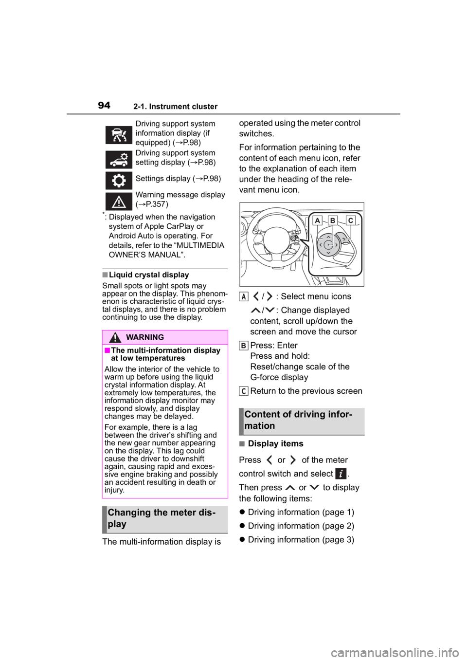
The multi-information display is operated using the meter control
switches.
For information pertaining to the
content of each menu icon, refer
to the explanation of each item
under the heading of the rele-
vant menu icon.
/ : Select menu icons
/ : Change displayed
content, scroll up/down the
screen and move the cursor
Press: Enter
Press and hold:
Reset/change scale of the
G-force display
Return to the previous screen
■Display items
Press or of the meter
control switch and select .
Then press or to display
the following items:
Driving information (page 1)
Driving information (page 2)
Driving information (page 3)
Driving support system
information display (if
equipped) ( P. 9 8 )
Driving support system
setting display ( P. 9 8 )
Settings display ( P. 9 8 )
Warning message display
( P.357)
WARNING
■The multi-information display
at low temperatures
Allow the interior of the vehicle to
warm up before u sing the liquid
crystal informat ion display. At
extremely low temperatures, the
information display monitor may
respond slowly, and display
changes may be delayed.
For example, there is a lag
between the driver’s shifting and
the new gear number appearing
on the display. This lag could
cause the driver to downshift
again, causing rapid and exces-
sive engine braking and possibly
an accident resulting in death or
injury.
Changing the meter dis-
play
Content of driving infor-
mation
A
C
Page 98 of 449
982-1. Instrument cluster
screen: Press .
To change to the top screen: Press .
Operating the measurement
screen
: Start/stop measurement
: Mark off one lap
: Reset measured lap times
: Scroll through the lap
times
Resetting measured lap times
After stopping the measurement,
press .
To display other content while
the stopwatch is operating
If the measurement screen is dis-
played, press to display the top
screen.
Then operate the meter control
switches to display other content.
While other items are displayed,
the measurement will continue but
the stopwatch cannot be operated.
Select to display the route guid-
ance information.
Select to enable selection of an
audio source or track on the dis-
play using the meter control switches.
Select to display the operational
status of the Adaptive Cruise
Control system (
P.190, 207)
The settings of the following
systems can be changed.
LDW (Lane Departure Warn-
ing) (if equipped)
PCB (Pre-Colli sion Braking)
(if equipped)
BSD/RCTA (if equipped)
RAB (Reverse Automatic
Braking system) (if equipped)
(Sonar Audible Alarm) (if
equipped)
SRH (Steering Responsive
Headlight) (if equipped)■Meter display settings that
can be changed
Units
Select to change the units of mea-
sure displayed.
Startup Scrn
Navigation system-linked
display
Audio system-linked dis-
play
Driving support system
information display (if
equipped)
Driving support system
setting display
Settings display
Page 123 of 449
1233-3. Adjusting the seats
3
Before driving
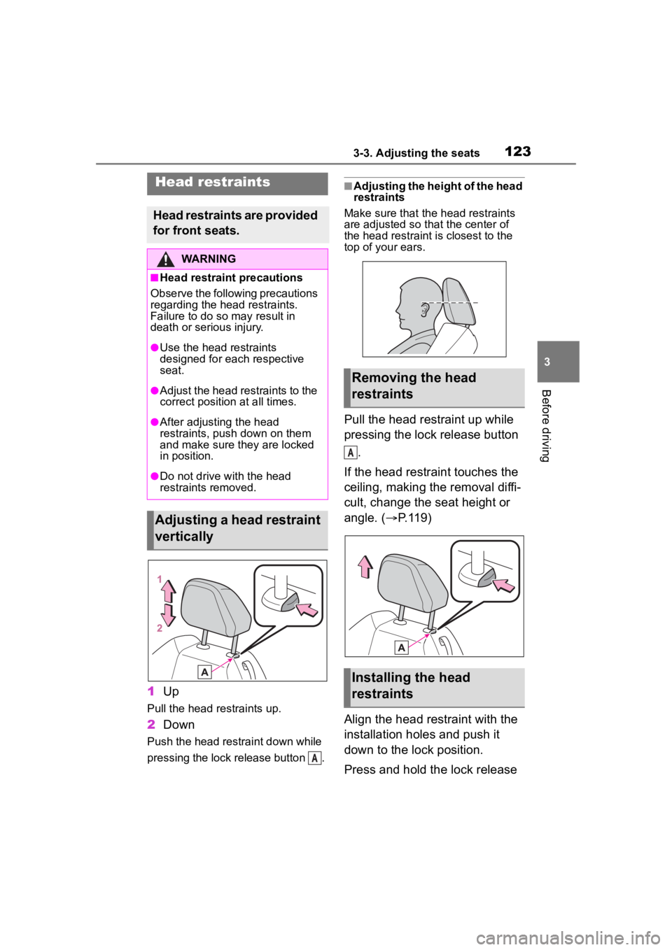
1Up
Pull the head restraints up.
2Down
Push the head restraint down while
pressing the lock release button .
■Adjusting the height of the head
restraints
Make sure that the head restraints
are adjusted so that the center of
the head restraint i s closest to the
top of your ears.
Pull the head restraint up while
pressing the lock release button
.
If the head restraint touches the
ceiling, making the removal diffi-
cult, change the seat height or
angle. ( P.119)
Align the head restraint with the
installation holes and push it
down to the lock position.
Press and hold the lock release
Head restraints
Head restraints are provided
for front seats.
WARNING
■Head restraint precautions
Observe the following precautions
regarding the head restraints.
Failure to do so m ay result in
death or serious injury.
●Use the head restraints
designed for each respective
seat.
●Adjust the head restraints to the
correct position at all times.
●After adjusting the head
restraints, push down on them
and make sure they are locked
in position.
●Do not drive with the head
restraints removed.
Adjusting a head restraint
vertically
A
Removing the head
restraints
Installing the head
restraints
A
Page 130 of 449
1303-5. Opening, closing the windows
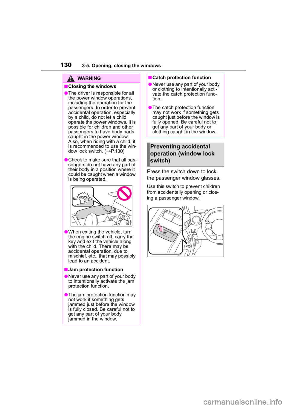
Press the switch down to lock
the passenger window glasses.
Use this switch to prevent children
from accidentally opening or clos-
ing a passenger window.
WARNING
■Closing the windows
●The driver is responsible for all
the power window operations,
including the operation for the
passengers. In or der to prevent
accidental operation, especially
by a child, do n ot let a child
operate the power windows. It is
possible for children and other
passengers to have body parts
caught in the power window.
Also, when riding with a child, it
is recommended to use the win-
dow lock switch. ( P.130)
●Check to make sure that all pas-
sengers do not have any part of
their body in a position where it
could be caught when a window
is being operated.
●When exiting the vehicle, turn
the engine switch off, carry the
key and exit the vehicle along
with the child. There may be
accidental operation, due to
mischief, etc., that may possibly
lead to an accident.
■Jam protection function
●Never use any part of your body
to intentionally a ctivate the jam
protection function.
●The jam protection function may
not work if something gets
jammed just before the window
is fully closed. Be careful not to
get any part of your body
jammed in the window.
■Catch protection function
●Never use any part of your body
or clothing to intentionally acti-
vate the catch protection func-
tion.
●The catch protection function
may not work if something gets
caught just before the window is
fully opened. Be careful not to
get any part of your body or
clothing caught in the window.
Preventing accidental
operation (window lock
switch)