2023 SUBARU BRZ trailer
[x] Cancel search: trailerPage 277 of 432

BSD/RCTA (If Equipped)
271
Starting and Operating7
– CONTINUED –
- When the temperature around
the radar sensors becomes
extremely low
- When the vehicle battery voltage
lowers
- When the vehicle voltage
exceeds the battery voltage rating
The BSD/RCTA will resume operation
once these conditions are corrected,
and the BSD/RCTA OFF indicator will
disappear. However, if the BSD/RCTA
OFF indicator appears for a prolonged
period of time, have the system
inspected at a SUBARU dealer as soon
as possible.
The detectability of the radar
sensors is restricted. The BSD/RCTA
detection may be impaired and the
system may not operate properly
under the following conditions. - When the rear bumper around
the radar sensors is distorted
- When ice, snow or mud adheres
to the rear bumper surface around
the radar sensors
- When stickers, etc. are affixed on
the areas of the radar sensors on the
rear bumper
- During adverse weather condi-
tions such as rain, snow or fog
- When driving on wet roads such
as snow-covered roads and through
puddles
The radar sensors may not detect or
may have difficulty detecting the
following vehicles and objects. - Small motorcycles, bicycles,
pedestrians, stationary objects on
the road or road side, etc.
- Vehicles with body shapes that
the radar may not reflect (vehicles
with lower body height such as a
trailer with no cargo and sports
cars)
- Vehicles that are not
approaching your vehicle even
though they are in the detection area
(either on a neighboring lane to the
rear or beside your vehicle when
reversing) (The system determines
the presence of approaching vehi-
cles based on data detected by the
radar sensors.)
- Vehicles traveling at signifi-
cantly different speeds
- Vehicles driving in parallel at
almost the same speed as your
vehicle for a prolonged time
- Oncoming vehicles
- Vehicles in a lane beyond the
neighboring lane
- Vehicles travelling at a signifi-
cantly lower speed that you are
trying to overtake
On a road with extremely narrow
lanes, the system may detect vehicles driving in a lane next to the neigh-
boring lane.
■
BSD/RCTA Approach Indi -
cator Light/Warning BuzzerWhile the BSD/RCTA is active, the
following item(s) will operate to alert the
driver:
The BSD/RCTA approach indicator
light (when there are v ehicles in the neigh-
boring lanes).
The BSD/RCTA approach indicator
light and warning buzzer (when a vehicle
is approaching from the left or right side
while your vehicle is reversing)
▼ BSD/RCTA approach indicator lightBSD/RCTA approach indicator light
702801
BRZ_U.book 271 ページ 2022年3月29日 火曜日 午後3時59分
Page 286 of 432

Reverse Automatic Braking (RAB) System (If Equipped)
280
- The rear bumper is exposed to
strong impact, or the rear bumper is
deformed.
On a steep hill, the system’s auto-
matic braking ability will be reduced.
The system is designed to avoid
collisions by automatic hard braking
when the vehicle’s reversing speed is
less than approximately 3 mph (5 km/
h). However, the system does not guar-
antee that the vehicle will be able to
avoid collisions in any situation.
If the vehicle is reversed at an
extremely slow speed, the driver’s
operation may be prioritized. In this
case, automatic braking will not
operate.
The system may not be able to
detect and apply the brake with the
following objects. - Sharp or thin objects such as
poles, fences and ropes which may
not reflect the s ound wave emitted
from the sonar sensor.
- Objects that are too close to the
rear bumper when the select lever is
set to the “R” position.
- Objects with a surface which
may not reflect the sound wave
emitted from the sonar sensor such
as a chain link fence.
Objects the system is not designed
to detect and apply brake. -Pedestrians.
- Moving objects including
moving vehicles.
- Objects which absorbs sound
waves such as cloth or snow.
- Objects whose surface has a
diagonal angle.
- Objects that are low to the
ground such as parking blocks.
- Objects that are high above the
ground such as objects hanging
from above.
- Objects that are out of range of
the center of the vehicle in the hori-
zontal direction.
- Objects that are not perpendic-
ular to the ground.
- The surface of the object is
uneven or wavy.
When reversing the vehicle, the
functions may not be able to work
properly or may cause a system
malfunction if the following conditions
exist.
High frequency sound from other
sources are nearby:
- Horn sound from another
vehicle.
- Engine sound from other vehi-
cles.
- Sound of an air brake.
- Vehicle detection equipment or a
sonar from another vehicle. - A sound wave with a frequency
similar to the vehicle’s system is
transmitted near by.
- A vehicle equipped with the
same system is reversing toward
your reversing direction.
Weather conditions:
- Extremely high or extremely low
temperatures in which the area near
the sonar sensor becomes too hot
or too cold to operate.
- The sonar sensors or the rear
bumper near the sonar sensors are
exposed to heavy rain or a signifi-
cant amount of water.
- Fog, snow or sandstorm, etc.
- Air is moving rapidly such as
when a strong wind is blowing.
Parts attached to the rear bumper
near the sonar sensor:
- Commercial electr onic parts (fog
light, fender pole, radio antenna) or
commercial attachment parts (trailer
hitch, bicycle carrier, bumper guard)
are attached.
- Parts that emit high frequency
sound, such as a horn or speaker,
are attached.
Vehicle conditions:
- Ice, snow or mud is adhered to
the sonar sensors or the rear
bumper near the sonar sensor.
BRZ_U.book 280 ページ 2022年3月29日 火曜日 午後3時59分
Page 295 of 432
Driving Tips8
Driving Tips
8-1. New Vehicle Break-In Driving – the First
1,000 miles (1,600 km) ......................................290
8-2. Fuel Economy Hints ...................... .....................290
8-3. Engine Exhaust Gas (Carbon Monoxide) .........290
8-4. Catalytic Converter .............................................291
8-5. Periodic Inspections ...........................................292
8-6. Driving in Foreign Coun tries .............................292
8-7. Driving Tips .........................................................292
8-8. Winter Driving .....................................................293
Operation during Cold Weather ..................................293 Driving on Snowy and Icy Roads ............................... 295
Corrosion Protection ................................................... 296
Snow Tires.................................................................... 296
Tire Chains ................................................................... 297
Rocking the Vehicle..................................................... 297
8-9. Loading Your Vehicle .........................................297
Vehicle Capacity Weight ............................................. 298
GVWR and GAWR (Gross Vehicle Weight Rating
and Gross Axle Weight Rating) ................................ 299
8-10. Trailer Towing ...................................................299
BRZ_U.book 289 ページ 2022年3月29日 火曜日 午後3時59分
Page 305 of 432
Trailer Towing
299
Driving Tips8
weight of the driver and all passengers,
their belongings, and any optional equip-
ment.■ GVWR and GAWR (Gross
Veh icle Weight Rating an d
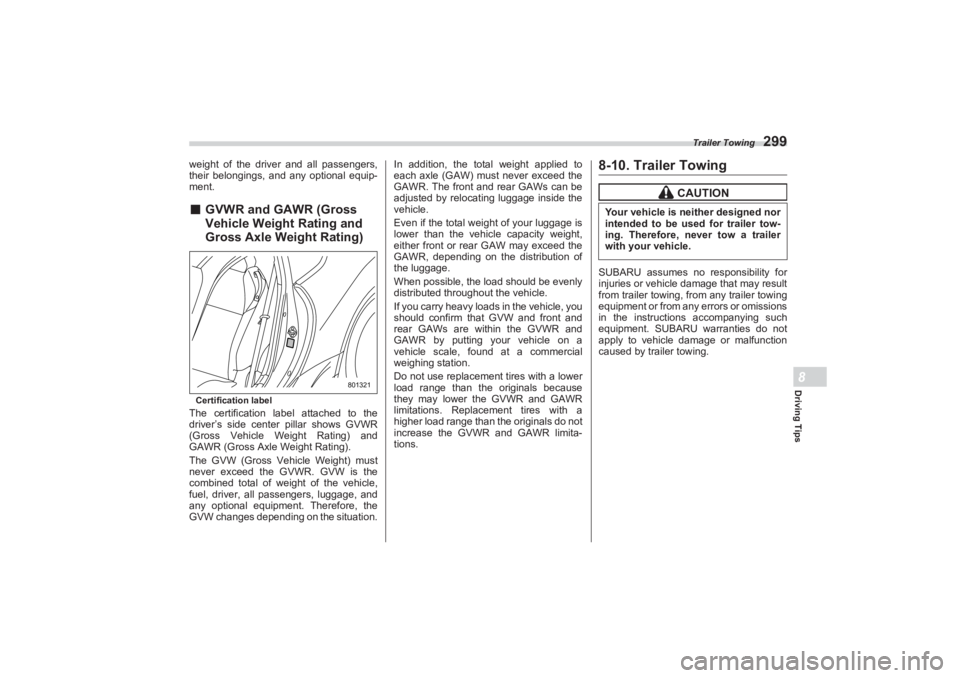
Gross Axle Weight Rating)Certification labelThe certification label attached to the
driver’s side center pillar shows GVWR
(Gross Vehicle Weight Rating) and
GAWR (Gross Axle Weight Rating).
The GVW (Gross Vehicle Weight) must
never exceed the GVWR. GVW is the
combined total of weight of the vehicle,
fuel, driver, all passengers, luggage, and
any optional equipment. Therefore, the
GVW changes depending on the situation. In addition, the tota
l weight applied to
each axle (GAW) must never exceed the
GAWR. The front and rear GAWs can be
adjusted by relocating luggage inside the
vehicle.
Even if the total weight of your luggage is
lower than the vehicl e capacity weight,
either front or rear GAW may exceed the
GAWR, depending on the distribution of
the luggage.
When possible, the load should be evenly
distributed throughout the vehicle.
If you carry heavy loads in the vehicle, you
should confirm that GVW and front and
rear GAWs are within the GVWR and
GAWR by putting your vehicle on a
vehicle scale, found at a commercial
weighing station.
Do not use replacement tires with a lower
load range than the originals because
they may lower the GVWR and GAWR
limitations. Replacement tires with a
higher load range than the originals do not
increase the GVWR and GAWR limita-
tions.
8-10. Trailer TowingSUBARU assumes no responsibility for
injuries or vehicle damage that may result
from trailer towing, from any trailer towing
equipment or from any errors or omissions
in the instructions accompanying such
equipment. SUBARU warranties do not
apply to vehicle damage or malfunction
caused by trailer towing.
801321
CAUTION
Your vehicle is neither designed nor
intended to be used for trailer tow-
ing. Therefore, never tow a trailer
with your vehicle.
BRZ_U.book 299 ページ 2022年3月29日 火曜日 午後3時59分
Page 314 of 432
Flat Tires
308Do not use tire chains on a sealed
tire. Do not tow a trailer.If used for a purpose other than
sealing a flat tire, the flat tire
repair kit may cause a severe
accident or injury due to the fact
that compressed air can act as an
explosive or propellant. Safely park your vehicle on the
roadside so that you do not
obstruct the flow of traffic and so
that you are able to seal the flat
tire without being in danger. Apply the parking brake, even if
the vehicle is parked on a level
road, to make sure that the
vehicle will not move. Stop the engine before sealing
the flat tire. Turn on the hazard warning
flasher while sealing the flat tire. Do not attempt to remove foreign
objects like nails or screws that
have penetrated the tire. Leave
them as they are. Never leave the flat tire repair kit
unattended while in use. Only one tire can be repaired with
one bottle of sealant.
The tires can be repaired when
the ambient temperature is −22 °F
( − 30 °C) or higher.
CAUTION
Remember that the flat tire repair
kit only provides temporary
mobility. Regulations concerning
tire repair after usage of flat tire
repair kit may di ffer from country
to country. We recommend that
you consult your SUBARU dealer
or tire dealer for advice. Store the flat tire repair kit safely
and secure it under the floor of
the trunk. Storing it anywhere in
the passenger compartment is
not advisable because it could
strike an occupant in the event of
a sudden stop or collision and
cause injury. Use the flat tire repair kit with
original vehicle tires only. Do not keep the air compressor
operating for more than 10
minutes, otherwise there is a risk
of overheating. The temperature of the air
compressor may become high.
Be careful not to burn yourself.
When raining, take measures to
prevent the air compressor from
being exposed directly to the
rain. Exposing to rain may cause
a malfunction. Do not use air compressors other
than the one in the repair kit.
Using an air compressor other
than the one in the repair kit may
damage the tires. Do not disassemble or modify the
air compressor to enable the use
of a power supply or a battery
other than DC 12 V. If a temporary puncture repair is
performed with the repair kit, the
Tire Pressure Monitoring System
(TPMS) (if equipped) may not
operate normally.
BRZ_U.book 308 ページ 2022年3月29日 火曜日 午後3時59分
Page 319 of 432
Flat Tires
313
In Case of Emergency9
– CONTINUED –
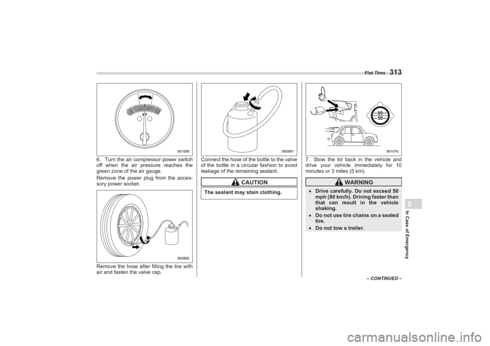
6. Turn the air compressor power switch
off when the air pressure reaches the
green zone of the air gauge.
Remove the power plug from the acces-
sory power socket.
Remove the hose after filling the tire with
air and fasten the valve cap. Connect the hose of the bottle to the valve
of the bottle in a circular fashion to avoid
leakage of the remaining sealant. 7. Stow the kit back in the vehicle and
drive your vehicle immediately for 10
minutes or 3 miles (5 km).
psi
40 40
20 20
30 30
0 0 0 0
901088900890
CAUTION
The sealant may stain clothing.
900891
WARNING
Drive carefully. Do not exceed 50
mph (80 km/h). Driving faster than
that can result in the vehicle
shaking. Do not use tire chains on a sealed
tire. Do not tow a trailer.
901076
BRZ_U.book 313 ページ 2022年3月29日 火曜日 午後3時59分
Page 408 of 432
Tire Information
402sures and make sure the wheel nuts
are correctly tightened. For informa-
tion about the tightening torque and
tightening sequence for the wheel
nuts, refer to
"Flat Tires"
P303.
■Vehicle Load Limit – How to
DetermineThe load capacity of your vehicle is
determined by weight, not by avail-
able cargo space. The load limit of
your vehicle is shown on the vehicle
placard attached to the driver’s side
B-pillar. Locate the statement “
The
combined weight of occupants and cargo
should never exceed XXX kg or XXX lbs
”
on your vehicle’s placard.
The vehicle placard also shows
seating capacity of your vehicle.
The total load capacity includes the
total weight of driver and all passen-
gers and their belongings, any
cargo, any optional equipment such
as a roof rack or bike carrier, etc.
Therefore cargo capacity can be
calculated by the following method. Cargo capacity = Load limit
− (total
weight of occupants + total weight of
optional equipment)
For information about vehicle
loading, refer to
"Loading Your Vehicle"
P297.▼
Calculating total and load
capacities varying seating
configurations
Calculate the available load
capacity as shown in the following
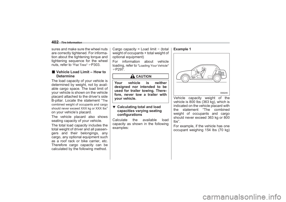
examples: Example 1
Vehicle capacity weight of the
vehicle is 800 lbs (363 kg), which is
indicated on the vehicle placard with
the statement “The combined
weight of occupants and cargo
should never exceed 363 kg or 800
lbs”.
For example, if the vehicle has one
occupant weighing 154 lbs (70 kg)
CAUTION
Your vehicle is neither
designed nor intended to be
used for trailer towing. There-
fore, never tow a trailer with
your vehicle.
D00245
BRZ_U.book 402 ページ 2022年3月29日 火曜日 午後3時59分
Page 425 of 432
Index
419
Index14
TPMS screen ....................................................................... P254
TRACK mode ...................................................................... P250
TrailerTowing ............................................................................ P299
Trip meter ............................................................................ P128
Trunk lid ............................................................................... P119 Release handle ............. .......................................... ........ P121
Trunk light ............................................................................ P374
Turn signal Indicator lights .......................... ....................................... P149
Lever ............................................................................... P182UUnder-floor storage compartment........................................ P219
USB power supply ....... ................................................... ..... P216VVanity mirror ........................................................................ P213
Light ................................................................................ P213
Vehicle Capacity weight.......... ................................................ ..... P298
Identification ........................... ......................................... P390
Symbols .............................................................................. P5
Vehicle data recording ................ ........................................... P10
Vehicle Stability Control (VSC)
OFF indicator light........................................................... P143
OFF switch ...................................................................... P248
Operation indicator light ........... ............................. P142, P143 Warning light ................................................................... P142
Vehicle Stability Control (VSC)/TRAC
System ............................................................................ P247
Ventilator.............................................................................. P198
Voltmeter ............................................................................. P153
WWarning and indicator lights ................................................ P131
Warning chimes
Keyless access with push-button start system................ P143
Seatbelt ........................................................................... P131
Warning indicator RAB .......................................................................P151, P286
Warning light
ABS ................................................................................. P140
Access key ...................................................................... P143
Access key fob ................................................................ P144
AT OIL TEMP .................................................................. P138
Automatic headlight beam levele r ................................... P150
Brake system .................................................................. P140
Charge ............................................................................ P137
CHECK ENGINE ............................................................. P136
Icy road surface............................................................... P151
Keyless access with push-button start system................ P143
LED headlight.................................................................. P150
Low fuel ........................................................................... P141
Low tire pressure............................................................. P138
Master ............................................................................. P151
Oil pressure ..................................................................... P137
BRZ_U.book 419 ページ 2022年3月29日 火曜日 午後3時59分