2023 SUBARU BRZ mirror
[x] Cancel search: mirrorPage 217 of 432
Interior Equipment6
Interior Equipment
6-1. Interior Light ........................................................212
Map Lights.....................................................................212
OFF Delay Timer ...........................................................212
6-2. Sun Visors ...........................................................213
Vanity Mirror with Light (If Equipped) ........................213
6-3. Storage Compartment ........................................213
Glove Box ......................................................................214
Center Console .............................................................214
6-4. Bottle Holders .....................................................215
6-5. Accessory Power Outlets ...................................215
6-6. USB Power Supply ..............................................216
How to Use the USB Power Supply ........................... 217
6-7. Ashtray (Dealer Option) ......................................217
6-8. Floor Mat ..............................................................218
6-9. Under-Floor Storage Compartment
(models with the flat tire repair kit) .................219
BRZ_U.book 211 ページ 2022年3月29日 火曜日 午後3時59分
Page 219 of 432
Sun Visors
213
Interior Equipment6
– CONTINUED –
6-2. Sun VisorsTo block out glare, swing down the visors.
To use the sun visor at a side window,
swing it down and move it sideways.■ Vanity Mirror with Light (If
Equipped)
To use the vanity mirror, swing down the
sun visor and open the vanity mirror
cover.
The lights beside the vanity mirror illumi-
nate when the mirror cover is opened.NOTEUse of the vanity mirror light for a long
period of time while the engine is not
running can cause battery discharge.
6-3. Storage Compartment
CAUTION
Keep the vanity mirror cover closed
while the car is being driven to
avoid being blinded by glare.
601182
602246
CAUTION
Keep the storage compartment
closed when it is not being used.
If left open, in the event of sudden
braking, etc., stowed items may
fly out, possibly leading to an
accident. Do not store the following items
in the storage compartment.
Otherwise, it may cause a fire or
accident.
- Spray cans, containers with
flammable or corrosive liquids
or any other dangerous items.- Plastic or other heat-vulner- able or flammable articles
such as a lighter.
BRZ_U.book 213 ページ 2022年3月29日 火曜日 午後3時59分
Page 234 of 432
Preparing to Drive
228have implemented emission inspection of
the OBDII system.
The inspection of the OBDII system
consists of a visual operational check of
the “ CHECK ENGINE ” warning light/
malfunction indicator light (MIL) and an
examination of the OBDII system with an
electronic scan tool.
A vehicle passes
the OBDII system
inspection if proper operation of the
“ CHECK ENGINE ” warning light is
observed, there are no stored diagnostic
trouble codes, and the OBDII readiness
monitors are all complete.
A vehicle fails
the OBDII inspection if
the “ CHECK ENGINE ” warning light is not
properly operating (light is illuminated or is
not working due to a burned out bulb) or
there is one or more diagnostic trouble
codes stored in the vehicle’s computer.
A state emission in spection may reject
(not pass or fail) a vehicle if the number of
OBDII system readiness monitors “ NOT
READY ” is greater than one. If the
vehicle’s battery has been recently
replaced or disconnected, the OBDII
system inspection may indicate that the
vehicle is not ready for the emission test.
Under this condition, the vehicle driver
should be instructed to drive his/her
vehicle for a few days to reset the readi-
ness monitors and return for an emission
re-inspection.
Owners of rejected or failing vehicles
should contact their SUBARU Dealer for
service.
7-3. Preparing to DriveYou should perform the following checks
and adjustments every day before you
start driving.
1. Check that all windows, mirrors, and
lights are clean and unobstructed.
2. Check the appearance and condition
of the tires. Also check tires for proper
inflation.
3. Look under the vehicle for any sign of
leaks.
4. Check that no small animals enter the
engine compartment.
5. Check that the hood and trunk are fully
closed.
6. Check the adjustment of the seat.
7. Check the adjustment of the inside
and outside mirrors.
8. Fasten your seatbelt. Check that your
passengers have fastened their seatbelts.
9. Check the operation of the warning
and indicator lights when the ignition
switch is turned to the “ON” position.
10. Check the gauges, indicator and
warning lights after starting the engine.
BRZ_U.book 228 ページ 2022年3月29日 火曜日 午後3時59分
Page 269 of 432
Rear View Camera
263
Starting and Operating7
– CONTINUED –
the switch. The vehicle speed at that
moment will be memorized and treated as
the new set speed.
When setting the displayed unit as
“MPH”:
The set speed can be decreased 1 mph
(1.6 km/h) each time by pushing the cruise
control switch to the “-SET” side.
When setting the displayed unit as
“km/h”:
The set speed can be decreased 1 km/h
(0.6 mph) each time by pushing the cruise
control switch to the “-SET” side.▼ To decrease the speed (by brake
pedal)
1. Depress the brake pedal to release
cruise control temporarily.
2. When the speed decreases to the
desired speed, push the cruise control
switch to the “-SET” side once. Now the
desired speed is set and the vehicle will
keep running at that speed without
depressing the accelerator pedal.■ Cruise Control Indicator
LightRefer to "Combination Meter Settings"
P130.
7-19. Rear View CameraA rear view camera is attached to the
trunk lid. When the ignition switch is in the
“ON” position and the shift lever (MT
models) or select lever (AT models) is set
to “R”, the rear view camera automatically
displays the rear view image behind the
vehicle on the center information display.
WARNING
Since the rear view camera uses a
wide-angle lens, the image on the
monitor is diffe rent from the
actual view in terms of distance.
702799
Since the range of the image on
the monitor is limited, always
check the rear view and the
surrounding area with your eyes
and mirrors, and move backward
at a slow speed. Moving back-
ward only by checking the rear
view image from the camera
could cause an accident. Do not disassemble or modify the
camera, switch or wiring. If
smoke comes out or you smell a
strange odor, stop using the rear
view camera immediately.
Contact your SUBARU dealer for
an inspection. Continued use
may result in accident, fire or
electric shock.
CAUTION
When washing your vehicle with
a high-pressure washer, do not
allow water to touch the camera
directly. Entry of water in the
camera lens may result in
condensation, malfunction, fire
or electric shock. Since the camera is a precision
device, do not subject it to strong
impacts. Otherwise, malfunction,
fire or electric shock may occur.
BRZ_U.book 263 ページ 2022年3月29日 火曜日 午後3時59分
Page 270 of 432

Rear View Camera
264NOTEDo not wipe the camera with
alcohol, benzine or paint thinner.
Otherwise, discoloration may occur.
To remove contamination, wipe the
camera with a cloth moistened with a
diluted neutral detergent. Then wipe it
with a soft, dry cloth.
When waxing the vehicle, be careful
not to apply the wax to the camera. If it
comes in contact with the camera,
moisten a clean cloth with a diluted
neutral detergent to remove the wax.
The camera lens has a hard coating
to help prevent scratches. However,
when washing the vehicle or cleaning
the camera lens, be careful not to
scratch the camera lens. Do not use a
washing brush directly on the camera
lens. The image quality of the rear view
camera may deteriorate.
Strong light shined on the camera
lens may develop vertical lines around
the light source. This is not a malfunc-
tion.
Under the fluorescent light, the
display may flicker. However, this is
not a malfunction.
The image of the rear view camera
may be slightly different from the
actual color of the objects.
If there is a malfunction on the
center information display, refer to
"Malfunctions of the Center Informa-
tion Display" P327.
■ How to Use the Rear View
CameraWhen the shift lever/se lect lever is set to
“R”, the rear view camera automatically
displays the rear view image from the vehicle. When the lever is set to other
positions, the image before setting to “R”
is displayed.
1. Set the ignition switch to “ON”.
2. Set the shift lever/ select lever to “R”.
NOTEThe image of the rear view camera is
horizontally reversed as is the case
with the vehicle inside mirror or the
outside mirror.
When “Rear Camera Delay Control”
is on, the rear view image from the rear
view camera will be displayed on the
center information display for a certain
amount of time after the shift lever (MT
models) or select lever (AT models) is
shifted from “R” to another position.
When any of the following conditions
are met, the rear view image will be
canceled: - The select lever is shifted to “P”
(AT models)
- The vehicle speed becomes
approximately 5 mph (8 km/h) or
more
- The parking brake is engaged
- 9 seconds have elapsed since
the shift lever (MT models) or select
lever (AT models) was shifted from
“R” to another position
If mud or snow sticks to or is
frozen on the camera, you must
be very careful when removing it.
Otherwise, damage to the camera
may cause a fire or electric shock.
Pour water or lukewarm water
over the camera to remove mud
and ice, and wipe it with a soft,
dry cloth. Do not put a flame close to the
camera or wiring. Otherwise,
damage or fire may occur. When replacing the fuse, be sure
to use a fuse with the specified
rating. Use of a fuse with a
different rating may result in a
malfunction. If you use the rear view camera
for a long time wh ile the engine is
not operated, the battery may
become completely discharged.
BRZ_U.book 264 ページ 2022年3月29日 火曜日 午後3時59分
Page 275 of 432
BSD/RCTA (If Equipped)
269
Starting and Operating7
– CONTINUED –
The system notifies the driver of the pres-
ence of vehicles in its blind spot.
If the system detects a vehicle in its
blind spot, it warns the driver by illumi-
nating the BSD/RCTA approach indicator
light(s) on the outside mirror(s).
If the driver operates the turn signal
lever in the direction where the BSD/
RCTA approach indicator light is illumi-
nating, the system warns the driver of
dangers by flashing the BSD/RCTA
approach indicator light.
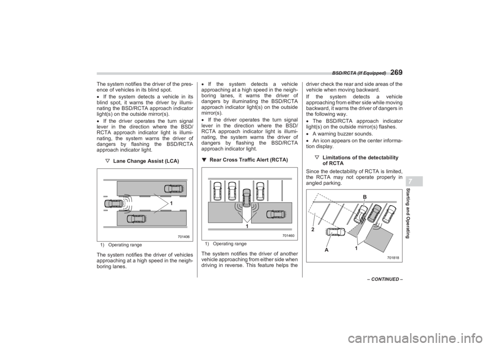
▽ Lane Change Assist (LCA)1) Operating rangeThe system notifies the driver of vehicles
approaching at a high speed in the neigh-
boring lanes.
If the system detects a vehicle
approaching at a high speed in the neigh-
boring lanes, it warns the driver of
dangers by illuminating the BSD/RCTA
approach indicator light(s) on the outside
mirror(s).
If the driver operates the turn signal
lever in the direction where the BSD/
RCTA approach indicator light is illumi-
nating, the system warns the driver of
dangers by flashing the BSD/RCTA
approach indicator light.
▼ Rear Cross Traffic Alert (RCTA)
1) Operating rangeThe system notifies the driver of another
vehicle approaching from either side when
driving in reverse. This feature helps the driver check the rear and side areas of the
vehicle when moving backward.
If the system detects a vehicle
approaching from either side while moving
backward, it warns the driver of dangers in
the following way.
The BSD/RCTA approach indicator
light(s) on the outside mirror(s) flashes.
A warning buzzer sounds.
An icon appears on the center informa-
tion display.
▽Limitations of the detectability
of RCTA
Since the detectabilit y of RCTA is limited,
the RCTA may not operate properly in
angled parking.
701406
1
701460
1
701818
2
A B
1
BRZ_U.book 269 ページ 2022年3月29日 火曜日 午後3時59分
Page 278 of 432
BSD/RCTA (If Equipped)
272It is mounted on each side of the outside
mirrors.
The indicator light will illuminate
when a
vehicle approaching from behind is
detected.
The indicator light will flash
to warn the
driver of dangers under the following
conditions.
While the indicator light is illuminating,
if the turn signal lever is operated toward
the side in which this light turned on
When reversing the vehicle while the
system detects a vehicle approaching
from either side
▽ BSD/RCTA approach indicator
light dimming function
When the headlights are turned on, the
brightness of the BSD/RCTA approach
indicator light will be reduced.
NOTE You may have difficulty seeing the
BSD/RCTA approach indicator light
under the following conditions. - When sunlight shines directly on
it
- When the headlight beams from
a vehicle traveling behind shines
directly on it
While the illumination brightness
control dial is in the fully upward posi- tion, even if the headlights are turned
on, the brightness of the BSD/RCTA
approach indicator light will not be
reduced. For details about the illumina-
tion brightness control dial, refer to
"Illumination Brightness Control"
P130.
▼ BSD/RCTA approach warning
buzzer (only when reversing)
A warning buzzer sounds along with
flashing of the BSD/RCTA approach indi-
cator light to warn the driver of dangers.
The setting of the warning buzzer volume
can be changed by operating the center
information display. For details, refer to
"Car settings" P165.
▼ Safety tips regarding the BSD/
RCTA approach indicator light/
warning buzzer
In the following cases, operation of the
BSD/RCTA approach indicator light and
the warning buzzer may be delayed or the
system may fail to issue these warnings.
- When a vehicle moves to the neigh-
boring lane from a lane next to the
neighboring lane
- When driving on a steep incline or
on repeated sharp uphill and downhill
grades
- When going beyond a pass - When both your vehicle and a
vehicle driving on a neighboring lane
are driving on the far side of each lane.
- When several narrowly-spaced
vehicles are approaching in a row
- In low radius bends (tight bends or
when making turns at an intersection)
- When there is a difference in height
between your lane and the neighboring
lane
- Immediately after the BSD/RCTA is
activated by touching “BSD/RCTA”
- Immediately after the shift lever/
select lever is shifted to the “R” position
- When extremely heavy cargo is
loaded in the trunk
During reversing, operation of the BSD/
RCTA approach indicator light and the
warning buzzer may be delayed or the
system may fail to issue these warnings
under the following conditions.
- When backing out of an angled
parking space
- When a large-sized vehicle is
parked next to your vehicle (That
vehicle prevents the propagation of
radar waves.)
- When reversing on sloped roads
- When reversing at a high speedBRZ_U.book 272 ページ 2022年3月29日 火曜日 午後3時59分
Page 395 of 432
Bulb Chart
389
Specifications12
– CONTINUED –
Wattage
Bulb No.
1) Map lights 12 V-8 W―
2) Trunk light 12 V-3.8 WSAE #194
3) Backup lights 12 V-16 WW16W
4) Door step lights (If equipped) 12 V-5 WW5W
5) Vanity mirror lights (If equipped) 12 V-2 W―
A) Front turn signal lights ――
B) Low and high beam headlights ――
C) High-mounted stop light ――
D) License plate lights ――
E) Rear side marker lights ――
F) Tail and stop lights ――
G) Stop lights ――
H) Rear turn signal lights ――
I) Front side marker lights ――
J) Front position lights ――
Daytime running lights ――
BRZ_U.book 389 ページ 2022年3月29日 火曜日 午後3時59分