2023 PEUGEOT 308 tow
[x] Cancel search: towPage 166 of 260
164
Practical information
Lower/upper screens
► Offer up one of the lower screens on the
corresponding side of the lower bumper grille,
aligning it around the number plate holder
.
►
Insert the fixing lugs into the bumper until
they are all properly seated.
►
Check that the unit is firmly held by pressing
around the edges.
Repeat the same steps for the other lower
screen, then for the upper screens in the upper
bumper grille, aligning them with the top of the
grille.
Centre screen
► Offer up the centre screen below the brand
badge.
►
Insert the fixing lugs into the bumper until
they are all properly seated.
►
Check that the unit is firmly held by pressing
around the edges.
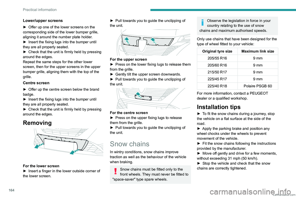
Removing
For the lower screen
► Insert a finger in the lower outside corner of
the lower screen.
► Pull towards you to guide the unclipping of
the unit.
For the upper screen
► Press on the lower fixing lugs to release them
from the grille.
►
Gently tilt the upper screen downwards.
►
Pull towards you to guide the unclipping of
the unit.
For the centre screen
► Press on the upper fixing lugs to release
them from the grille.
►
Pull towards you to guide the unclipping of
the unit.
Snow chains
In wintry conditions, snow chains improve
traction as well as the behaviour of the vehicle
when braking.
Snow chains must be fitted only to the
front wheels. They must never be fitted to
"space-saver" type spare wheels.
Observe the legislation in force in your
country relating to the use of snow
chains and maximum authorised speeds.
Only use chains that have been designed for the
type of wheel fitted to your vehicle:
Original tyre size Maximum link size 205/55 R16 9 mm
205/60 R16 9 mm
215/50 R17 9 mm
225/45 R17 9 mm
225/40 R18 Polaire PSGB 60
For more information, contact a PEUGEOT
dealer or a qualified workshop.
Installation tips
► To fit the snow chains during a journey, stop
the vehicle on a flat surface at the side of the
road.
►
Apply the parking brake and position any
wheel chocks under the wheels to prevent
movement of the vehicle.
►
Fit the snow chains following the instructions
provided by the manufacturer
.
►
Move off gently and drive for a few moments,
without exceeding 31
mph (50 km/h).
►
Stop the vehicle and check that the snow
chains are correctly tightened. CarM an uals 2 .c o m
Page 168 of 260

166
Practical information
When the engine is hot, handle the
exterior safety catch and the bonnet stay
with care (risk of burns), using the protected
area.
When the bonnet is open, take care not to
damage the safety catch.
Do not open the bonnet under very windy
conditions.
Cooling of the engine when stopped
The engine cooling fan may start after
the engine has been switched off.
Take care with objects or clothing that
could be caught in the blades of the fan!
Opening
► Open the left- hand front door.
► Pull the interior release lever , located at the
bottom of the door frame, towards you.
► Lift the exterior safety catch and raise the
bonnet.
►
Unclip the stay from its housing and place it
in the support slot to hold the bonnet open.
Closing
► Lower the bonnet and release it near the end
of its travel.
►
Check the locking.
Because of the presence of electrical
equipment under the bonnet, it is strongly
recommended that exposure to water (rain,
washing, etc.) be limited.
Engine compartment
The engine shown here is an example for
illustrative purposes only.
The locations of the following components may
vary: –
Air filter
.
–
Engine oil dipstick.
–
Engine oil filler cap.
Petrol engine
Diesel engine
1.
Screenwash fluid reservoir
2. Engine coolant reservoir
3. Brake fluid reservoir
4. Battery/Fuses
5. Remote earth point (-)
6. Fusebox
7. Air filter
8. Engine oil filler cap
9. Engine oil dipstick CarM an uals 2 .c o m
Page 171 of 260
169
Practical information
7Otherwise, have them checked by a PEUGEOT
dealer or a qualified workshop.
Only use products recommended by
PEUGEOT or products of equivalent
quality and specification.
In order to optimise the operation of
components as important as those in the
braking system, PEUGEOT selects and offers
very specific products.
12 V battery
The battery does not require any maintenance.
Check regularly that the terminals are correctly
tightened (versions without quick-release
terminals) and that the connections are clean.
For more information on the precautions
to take before any work on the 12 V
battery, refer to the corresponding section.
Versions equipped with Stop & Start are
fitted with a 12 V lead-acid battery with
special technology and specifications.
Its replacement should be carried out only by
a PEUGEOT dealer or a qualified workshop.
Passenger compartment
filter
Depending on the environment and the
use of the vehicle (e.g. dusty atmosphere,
city driving), change it twice as often, if
necessary .
A clogged passenger compartment filter
can adversely affect air conditioning
system performance and generate
undesirable odours.
Air filter
Depending on the environment and the
use of the vehicle (e.g. dusty atmosphere,
city driving), change it twice as often, if
necessary .
Oil filter
Change the oil filter each time the engine
oil is changed.
Particle filter (Diesel)
The start of clogging of the particle filter is
indicated by the temporary lighting of this
warning lamp, accompanied by an alert
message.
As soon as traffic conditions allow, regenerate
the filter by driving at a speed of at least 37
mph
(60
km/h), with an engine speed above 2,500
rpm, for about 15 minutes (until the warning lamp
goes out).
If it is not possible to reach 37
mph (60 km/h),
leave the engine running at idle for about 15
minutes, then drive with an engine speed
above
2,500 rpm for 15 minutes.
Do not switch off the engine until the filter
is fully regenerated; repeated intervals
can degrade the engine oil prematurely.
Regenerating the filter while the vehicle is
stationary is not recommended.
Following prolonged operation of the
vehicle at very low speed or at idle, you
may, in exceptional circumstances, notice
water vapour coming from the exhaust while
accelerating. These emissions have no
impact on the vehicle’s behaviour and the
environment.
New vehicle
During the first few particle filter
regeneration operations, you may notice a
"burning" smell. This is perfectly normal.
Manual gearbox
The gearbox does not require any maintenance (no oil change).
Automatic gearbox
The gearbox does not require any maintenance (no oil change).
Brake pads
Brake wear depends on the style of
driving, particularly in the case of vehicles
used in town, over short distances. It may be CarM an uals 2 .c o m
Page 174 of 260
172
Practical information
Store AdBlue® out of the reach of
children, in its original container.
Procedure
Before starting the top-up procedure, ensure that
the vehicle is parked on a flat and level surface.
In wintry conditions, ensure that the temperature
of the vehicle is above -11°C. Otherwise the
AdBlue
® may be frozen and so cannot be poured
into the tank. Park the vehicle in a warmer area
for a few hours to allow the top-up to be carried
out.
Never pour the AdBlue® into the Diesel
fuel tank.
If any AdBlue® is splashed, or if there are
any spillages on the bodywork, rinse
immediately with cold water or wipe with a
damp cloth.
If the fluid has crystallised, clean it off using a
sponge and hot water.
Important: in the event of a top-up after
an AdBlue breakdown, you must wait
about 5
minutes before switching on the
ignition, without opening the driver's door,
unlocking the vehicle or bringing the
electronic key into the passenger
compartment.
Switch on the ignition, then wait for 10
seconds before starting the engine.
► Press the " START/STOP" button to switch off
the engine.
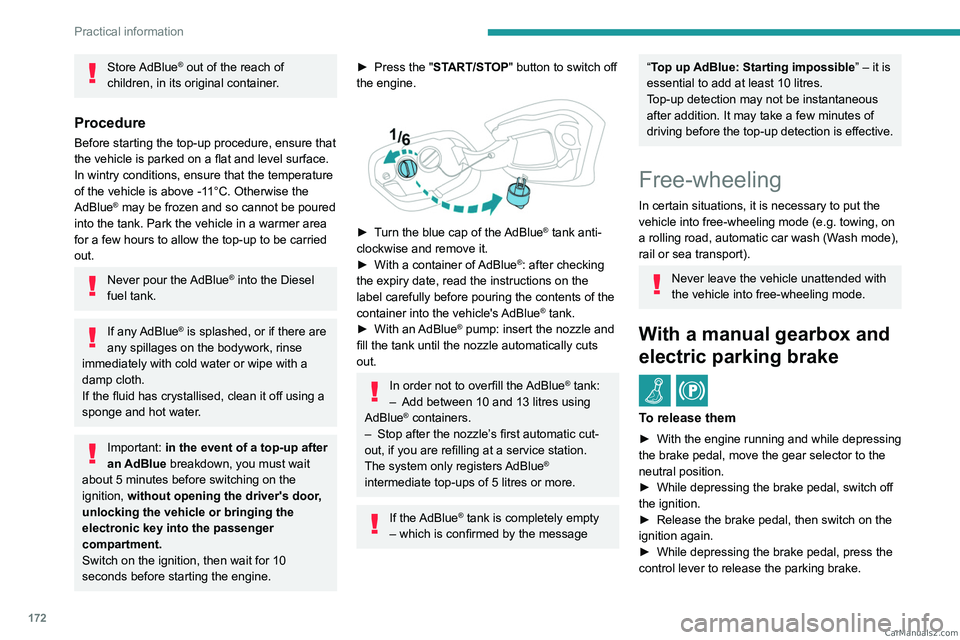
► Turn the blue cap of the AdBlue® tank anti-
clockwise and remove it.
►
With a container of
AdBlue
®: after checking
the expiry date, read the instructions on the
label carefully before pouring the contents of the
container into the vehicle's AdBlue
® tank.
►
With an
AdBlue® pump: insert the nozzle and
fill the tank until the nozzle automatically cuts
out.
In order not to overfill the AdBlue® tank:
–
Add between 10 and 13 litres using
AdBlue® containers.
–
Stop after the nozzle’ s first automatic cut-
out, if you are refilling at a service station.
The system only registers AdBlue
®
intermediate top-ups of 5
litres or more.
If the AdBlue® tank is completely empty
– which is confirmed by the message
“Top up AdBlue: Starting impossible ” – it is
essential to add at least 10 litres.
Top-up detection may not be instantaneous
after addition. It may take a few minutes of
driving before the top-up detection is effective.
Free-wheeling
In certain situations, it is necessary to put the
vehicle into free-wheeling mode (e.g. towing, on
a rolling road, automatic car wash (Wash mode),
rail or sea transport).
Never leave the vehicle unattended with
the vehicle into free-wheeling mode.
With a manual gearbox and
electric parking brake
/
To release them
► With the engine running and while depressing
the brake pedal, move the gear selector to the
neutral position.
►
While depressing the brake pedal, switch off
the ignition.
►
Release the brake pedal, then switch on the
ignition again.
►
While depressing the brake pedal, press the
control lever to release the parking brake. CarM an uals 2 .c o m
Page 180 of 260
178
In the event of a breakdown
The jack meets European standards, as
defined in the Machinery Directive 2006/42/
CE.
The jack does not require any maintenance.
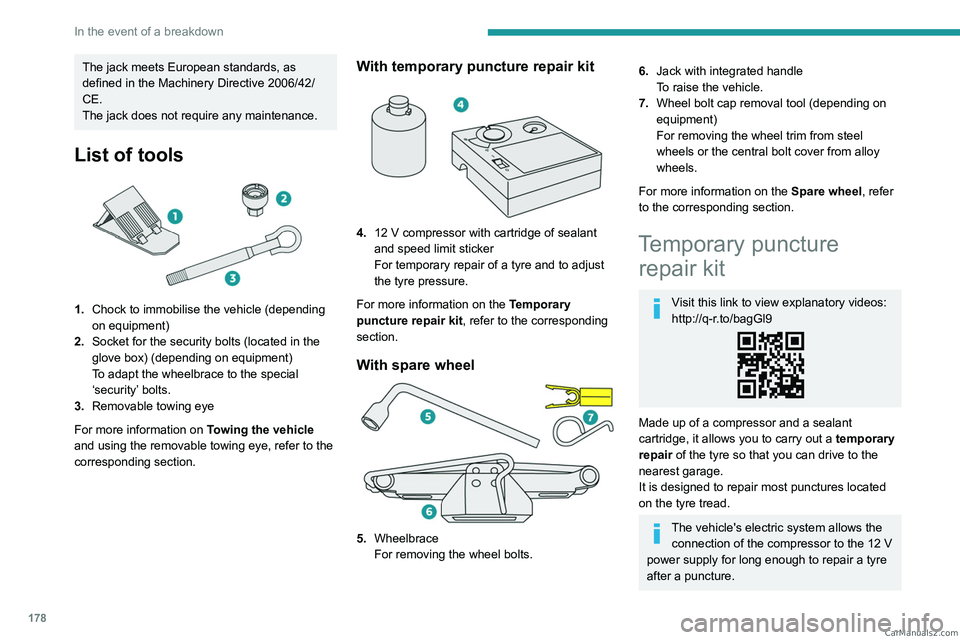
List of tools
1.Chock to immobilise the vehicle (depending
on equipment)
2. Socket for the security bolts (located in the
glove box) (depending on equipment)
To adapt the wheelbrace to the special
‘security’ bolts.
3. Removable towing eye
For more information on Towing the vehicle
and using the removable towing eye, refer to the
corresponding section.
With temporary puncture repair kit
4. 12 V compressor with cartridge of sealant
and speed limit sticker
For temporary repair of a tyre and to adjust
the tyre pressure.
For more information on the Temporary
puncture repair kit, refer to the corresponding
section.
With spare wheel
5. Wheelbrace
For removing the wheel bolts.
6.Jack with integrated handle
To raise the vehicle.
7. Wheel bolt cap removal tool (depending on
equipment)
For removing the wheel trim from steel
wheels or the central bolt cover from alloy
wheels.
For more information on the Spare wheel, refer
to the corresponding section.
Temporary puncture repair kit
Visit this link to view explanatory videos:
http://q-r.to/bagGl9
Made up of a compressor and a sealant
cartridge,
it allows you to carry out a temporary
repair of the tyre so that you can drive to the
nearest garage.
It is designed to repair most punctures located
on the tyre tread.
The vehicle's electric system allows the connection of the compressor to the 12 V
power supply for long enough to repair a tyre
after a puncture. CarM an uals 2 .c o m
Page 181 of 260
179
In the event of a breakdown
8Only the 12 V socket located at the front
of the vehicle can be used to power the
compressor.
For more information on the Tool kit,
refer to the corresponding section.
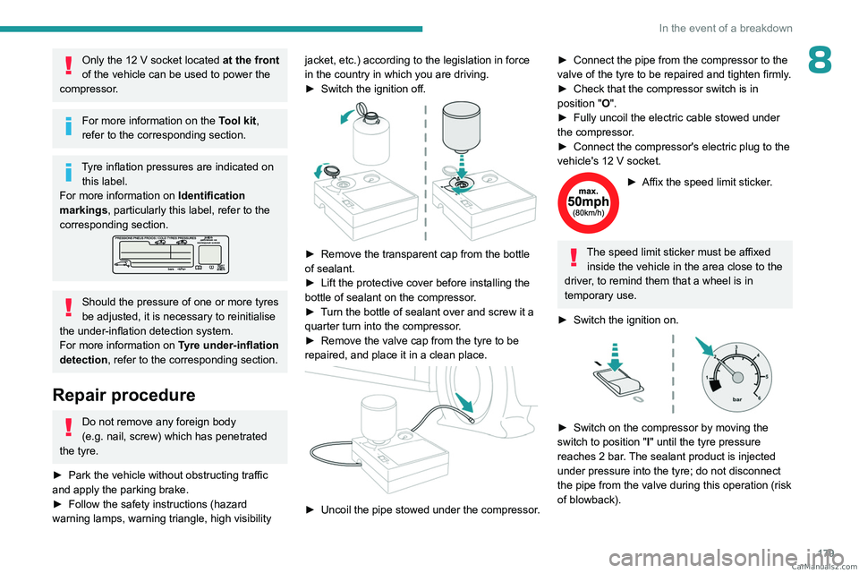
Tyre inflation pressures are indicated on this label.
For more information on Identification
markings, particularly this label, refer to the
corresponding section.
Should the pressure of one or more tyres
be adjusted, it is necessary to reinitialise
the under-inflation detection system.
For more information on Tyre under-inflation
detection, refer to the corresponding section.
Repair procedure
Do not remove any foreign body
(e.g. nail, screw) which has penetrated
the tyre.
►
Park the vehicle without obstructing traffic
and apply the parking brake.
►
Follow the safety instructions (hazard
warning lamps, warning triangle, high visibility jacket, etc.) according to the legislation in force
in the country in which you are driving.
►
Switch the ignition off.
► Remove the transparent cap from the bottle
of sealant.
►
Lift the protective cover before installing the
bottle of sealant on the compressor
.
►
T
urn the bottle of sealant over and screw it a
quarter turn into the compressor.
►
Remove the valve cap from the tyre to be
repaired, and place it in a clean place.
► Uncoil the pipe stowed under the compressor.
► Connect the pipe from the compressor to the
valve of the tyre to be repaired and tighten firmly .
►
Check that the compressor switch is in
position
"O".
►
Fully uncoil the electric cable stowed under
the compressor
.
►
Connect the compressor's electric plug to the
vehicle's 12
V socket.
► Affix the speed limit sticker .
The speed limit sticker must be affixed
inside the vehicle in the area close to the
driver, to remind them that a wheel is in
temporary use.
►
Switch the ignition on.
► Switch on the compressor by moving the
switch to position "I" until the tyre pressure
reaches 2
bar. The sealant product is injected
under pressure into the tyre; do not disconnect
the pipe from the valve during this operation (risk
of blowback). CarM an uals 2 .c o m
Page 182 of 260
180
In the event of a breakdown
If after approximately 7 minutes, the
pressure of 2 bar is not reached, this
indicates that the tyre is not repairable;
contact a PEUGEOT dealer or a qualified
workshop for assistance.
►
Move the switch to position
"O".
►
Disconnect the compressor's electric plug
from the vehicle's 12
V socket.
►
Remove the kit.
►
Refit the cap on the valve.
►
Remove and store the bottle of sealant.
The sealant product is harmful if swallowed and causes irritation to the
eyes.
Keep this product out of the reach of children.
The use-by date of the fluid is marked on the
bottle.
After use, do not discard the bottle into the
environment; take it to a PEUGEOT dealer or
an authorised waste disposal site.
Do not forget to obtain a new bottle of
sealant, available from a PEUGEOT dealer or
a qualified workshop.
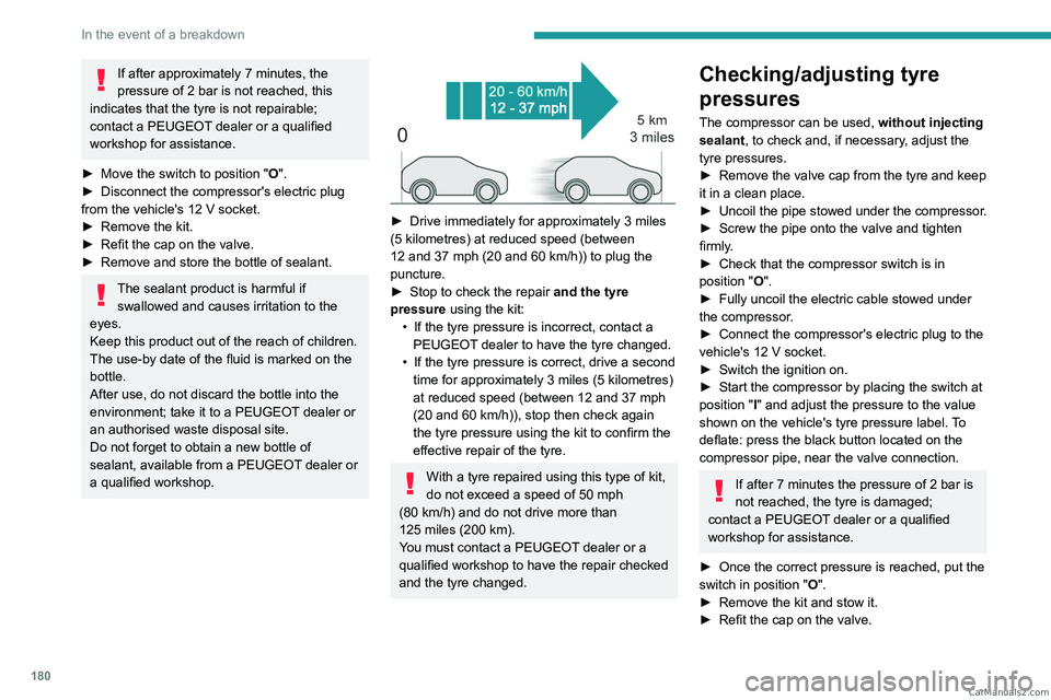
► Drive immediately for approximately 3 miles
(5 kilometres) at reduced speed (between
12 and 37
mph (20 and 60 km/h)) to plug the
puncture.
►
Stop to check the repair
and the tyre
pressure using the kit:
•
If the tyre pressure is incorrect, contact a
PEUGEOT
dealer to have the tyre changed.
•
If the tyre pressure is correct, drive a second
time for approximately 3
miles (5 kilometres)
at reduced speed (between 12 and 37
mph
(20 and 60
km/h)), stop then check again
the tyre pressure using the kit to confirm the
effective repair of the tyre.
With a tyre repaired using this type of kit,
do not exceed a speed of 50 mph
(80
km/h) and do not drive more than
125
miles (200 km).
You must contact a PEUGEOT dealer or a
qualified workshop to have the repair checked
and the tyre changed.
Checking/adjusting tyre
pressures
The compressor can be used, without injecting
sealant, to check and, if necessary, adjust the
tyre pressures.
►
Remove the valve cap from the tyre and keep
it in a clean place.
►
Uncoil
the pipe stowed under the compressor.
►
Screw the pipe onto the valve and tighten
firmly
.
►
Check that the compressor switch is in
position
"O".
►
Fully uncoil the electric cable stowed under
the compressor
.
►
Connect the compressor's electric plug to the
vehicle's 12
V socket.
►
Switch the ignition on.
►
Start the compressor by placing the switch at
position
"I" and adjust the pressure to the value
shown on the vehicle's tyre pressure label. To
deflate: press the black button located on the
compressor pipe, near the valve connection.
If after 7 minutes the pressure of 2 bar is
not reached, the tyre is damaged;
contact a PEUGEOT
dealer or a qualified
workshop for assistance.
►
Once the correct pressure is reached, put the
switch in position
"O".
►
Remove the kit and stow it.
►
Refit the cap on the valve. CarM an uals 2 .c o m
Page 183 of 260
181
In the event of a breakdown
8Spare wheel
Visit this link to view explanatory videos:
http://q-r.to/bagGl9
For more information on the Tool kit,
refer to the corresponding section.
Accessing the spare wheel
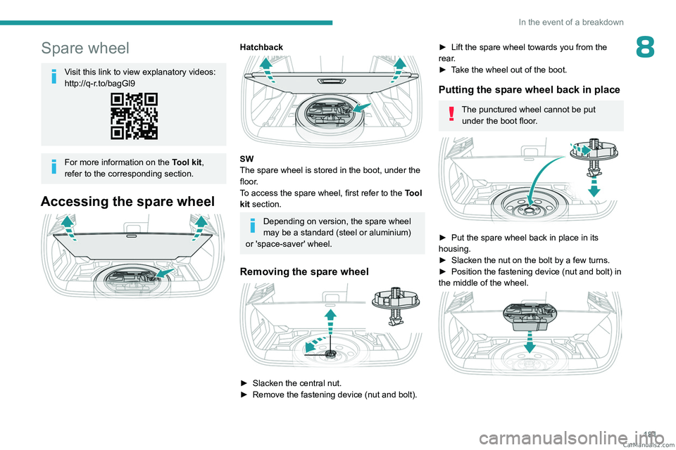
Hatchback
SW
The spare wheel is stored in the boot, under the
floor.
To access the spare wheel, first refer to the Tool
kit section.
Depending on version, the spare wheel
may be a standard (steel or aluminium)
or 'space-saver' wheel.
Removing the spare wheel
► Slacken the central nut.
► Remove the fastening device (nut and bolt).
► Lift the spare wheel towards you from the
rear .
►
T
ake the wheel out of the boot.
Putting the spare wheel back in place
The punctured wheel cannot be put under the boot floor.
► Put the spare wheel back in place in its
housing.
►
Slacken the nut on the bolt by a few turns.
►
Position the fastening device (nut and bolt) in
the middle of the wheel.
CarM an uals 2 .c o m