2023 PEUGEOT 308 ECU
[x] Cancel search: ECUPage 93 of 260
91
Safety
5For more information on the ISOFIX mountings, refer to the corresponding section.
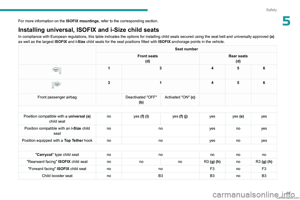
Installing universal, ISOFIX and i-Size child seats
In compliance with European regulations, this table indicates the option\
s for installing child seats secured using the seat belt and universally\
approved (a)
as well as the largest ISOFIX and i-Size child seats for the seat positions fitted with ISOFIX anchorage points in the vehicle.
Seat number
Front seats (d) Rear seats
(d)
1 3456
3 1456
Front passenger airbag Deactivated "OFF"
(b) Activated "ON" (c)
Position compatible with a universal (a)
child seat no
yes (f) (i) yes (f) (j)yes yes (e) yes
Position compatible with an i-Size child
seat no
noyesnoyes
Position equipped with a Top Tether hook no noyesnoyes
"Carrycot " type child seat nonononono
"Rearward facing" ISOFIX child seat nono noR3 (g) (h) no R3 (g) (h)
"Forward facing" ISOFIX child seat no noF3noF3
Child booster seat noB3 B3noB3 CarM an uals 2 .c o m
Page 94 of 260
92
Safety
Rules:
– A position that is i-Size compatible is also
compatible with R1, R2 and F2X, F2, B2.
–
A
position that is R3 compatible is also
compatible with R1 and R2.
–
A
position that is F3 compatible is also
compatible with F2X and F2.
–
A
position that is B3 compatible is also
compatible with B2.
(a) Universal child seat: child seat that can be
installed in all vehicles using the seat belt.
(b) To install a "rearward facing" child seat at
this seat position, the front passenger airbag
must be deactivated ("OFF").
(c) Only a "forward facing" child seat is
authorised at this seat position with the front
passenger airbag activated (" ON").
(d) Depending on version, refer to the
legislation in force in your country before
installing a child in this seat position.
(e) Never install a child seat with a support leg
on the centre rear seat.
(f) For a seat with height adjustment, adjust
the seat to the highest position and move it
fully back.
(g) Adjust the driver's seat to the highest
position.
(h) Adjust the passenger seat to the
intermediate forward longitudinal position. (i)
For a universal " rearward facing" and/or
"forward facing" (U) child seat in groups 0,
0+, 1, 2 or 3.
(j) For a universal " forward facing" (UF) child
seat in groups 1, 2 or 3.
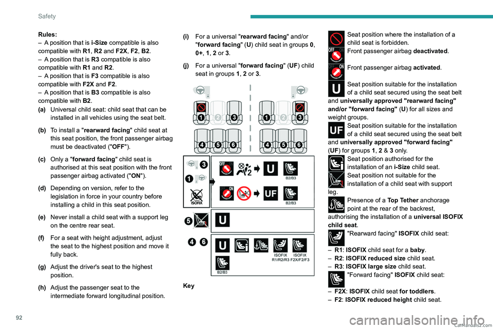
Key
Seat position where the installation of a
child seat is forbidden.
Front passenger airbag deactivated.
Front passenger airbag activated.
Seat position suitable for the installation
of a child seat secured using the seat belt
and universally approved "rearward facing"
and/or "forward facing" (U) for all sizes and
weight groups.
Seat position suitable for the installation
of a child seat secured using the seat belt
and universally approved "forward facing"
(UF) for groups 1, 2 & 3 only.
Seat position authorised for the
installation of an i-Size child seat.
Seat position not suitable for the
installation of a child seat with support
leg.
Presence of a Top Tether anchorage
point at the rear of the backrest,
authorising the installation of a universal ISOFIX
child seat.
"Rearward facing" ISOFIX child seat:
–
R1
: ISOFIX child seat for a baby.
–
R2
: ISOFIX reduced size child seat.
–
R3
: ISOFIX large size child seat.
"Forward facing" ISOFIX child seat:
–
F2X
: ISOFIX child seat for toddlers.
–
F2
: ISOFIX reduced height child seat. CarM an uals 2 .c o m
Page 112 of 260
11 0
Driving
Mats/Pedal trims
The use of mats or pedal trims not
approved by PEUGEOT may interfere with
the operation of the speed limiter or cruise
control.
To avoid any risk of jamming the pedals:
–
Ensure that the mat is secured correctly
.
–
Never fit one mat on top of another
.
Units of speed
Ensure that the units of speed displayed
on the instrument panel (mph or km/h) are
those for the country you are driving in.
If this is not the case, when the vehicle is
stationary, set the display to the required
units of speed so that it complies with what is
authorised locally.
In case of doubt, contact a PEUGEOT dealer
or a qualified workshop.
Steering wheel with
hands-on detection
(with Drive Assist 2.0)
For more information, refer to the
General recommendations on the use
of driving and manoeuvring aids .
The steering wheel is equipped with a hands-on
detection system to avoid distraction on the part
of the driver.
It is prohibited to cover or attach anything to the
steering wheel.
The driver must always check the surroundings of the vehicle and
supervise the whole manoeuvre.
Any use of a system built into
Drive Assist
2.0
must remain under the driver’s vigilance.
The system also detects the presence of
hands when using the Lane Positioning assist
system with Drive Assist Plus.
The system may suffer interference or not work correctly if:
–
the steering wheel is covered by some
protection.
–
the driver wears thick gloves (e.g.
ski
gloves).
In the event of improper detection of hands
on the steering wheel, Drive Assist 2.0 is
not activated or is deactivated after a few
seconds.
Installation of mechanical anti-theft
devices on the steering wheel is
prohibited - risk of damage!
Shortcuts for driving aids
The full list of available driving aids can be found
in the Functions tab. Driving aids can be accessed directly to quickly
activate/deactivate them.
By default, driving aids are already stored in the
Shortcuts tab (e.g.
Stop & Start, Lane keeping
assist).
Other driving aids can be added or deleted from
this tab.
It is configured in the ADAS>Functions
touch screen application.
► Press the button corresponding to the
driving assistance concerned:
•
Full symbol: the function is added to the
Shortcuts
tab.
•
Empty symbol: the function is deleted from
the
Shortcuts tab.
►
Check the modification in the Shortcuts
tab.
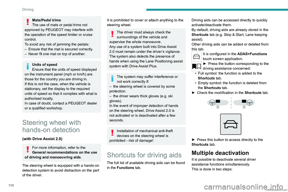
► Press this button to access directly to the
Shortcuts tab.
Multiple deactivation
It is possible to deactivate several driver
assistance functions simultaneously.
This is done in two steps: CarM an uals 2 .c o m
Page 161 of 260
159
Practical information
7Vehicle equipped with motorised
tailgate with hands-free function
(Hands-Free Tailgate Access)
To avoid unintentionally opening the
motorised tailgate when operating the towing
device:
–
Deactivate this function in advance in the
vehicle's configuration application.
–
Or remove the electronic key from the
recognition zone, with the tailgate closed.
Towing device with quickly detachable towball
Presentation
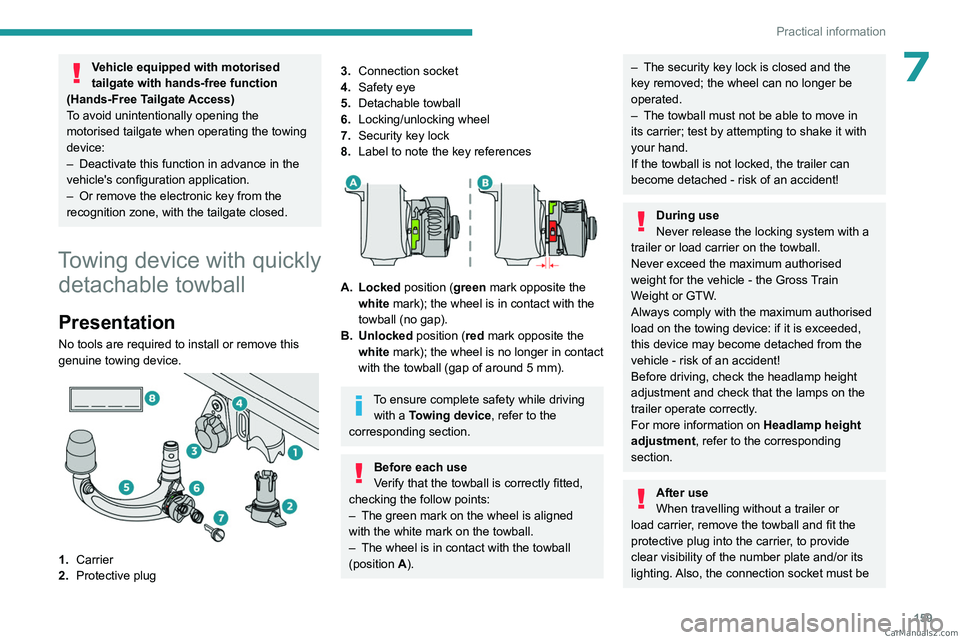
No tools are required to install or remove this
genuine towing device.
1. Carrier
2. Protective plug
3.Connection socket
4. Safety eye
5. Detachable towball
6. Locking/unlocking wheel
7. Security key lock
8. Label to note the key references
A. Locked position (green mark opposite the
white mark); the wheel is in contact with the
towball (no gap).
B. Unlocked position (red mark opposite the white mark); the wheel is no longer in contact
with the towball (gap of around 5
mm).
To ensure complete safety while driving with a Towing device , refer to the
corresponding section.
Before each use
Verify that the towball is correctly fitted,
checking the follow points:
–
The green mark on the wheel is aligned
with the white mark on the towball.
–
The wheel is in contact with the towball
(position A
).
– The security key lock is closed and the
key removed; the wheel can no longer be
operated.
–
The towball must not be able to move in
its carrier; test by attempting to shake it with
your hand.
If the towball is not locked, the trailer can
become detached - risk of an accident!
During use
Never release the locking system with a
trailer or load carrier on the towball.
Never exceed the maximum authorised
weight for the vehicle - the Gross Train
Weight or GTW.
Always comply with the maximum authorised
load on the towing device: if it is exceeded,
this device may become detached from the
vehicle - risk of an accident!
Before driving, check the headlamp height
adjustment and check that the lamps on the
trailer operate correctly.
For more information on Headlamp height
adjustment, refer to the corresponding
section.
After use
When travelling without a trailer or
load carrier, remove the towball and fit the
protective plug into the carrier, to provide
clear visibility of the number plate and/or its
lighting. Also, the connection socket must be CarM an uals 2 .c o m
Page 165 of 260
163
Practical information
7Recommendations
Distribute the load uniformly, taking care
to avoid overloading one of the sides.
Arrange the heaviest part of the load as close
as possible to the roof.
Secure the load firmly.
Drive gently: the vehicle will be more
susceptible to the effects of side winds and its
stability may be affected.
Regularly check the security and tight
fastening of the roof bars, at least before each
trip.
Sunroof
Do not operate the sunroof when using
roof bars - risk of major damage!
Very cold climate screens
(Depending on country of sale)
Only available for Diesel vehicles.
This removable device prevents the
accumulation of snow around the radiator
cooling fan.
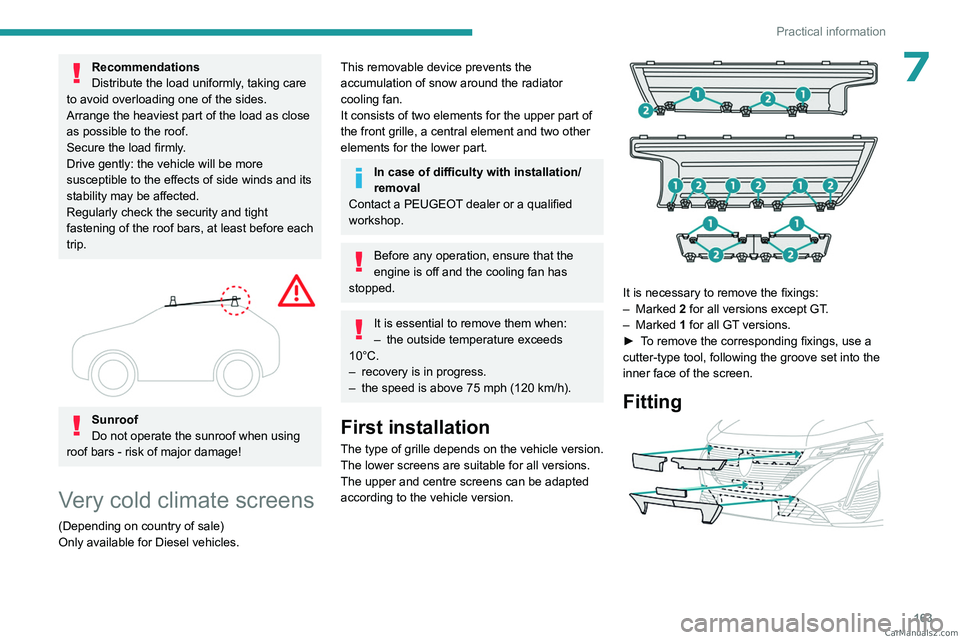
It consists of two elements for the upper part of
the front grille, a central element and two other
elements for the lower part.
In case of difficulty with installation/
removal
Contact a PEUGEOT dealer or a qualified
workshop.
Before any operation, ensure that the
engine is off and the cooling fan has
stopped.
It is essential to remove them when:
– the outside temperature exceeds
10°C.
–
recovery is in progress.
–
the speed is above 75 mph (120
km/h).
First installation
The type of grille depends on the vehicle version.
The lower screens are suitable for all versions.
The upper and centre screens can be adapted
according to the vehicle version.
It is necessary to remove the fixings:
– Marked 2
for all versions except GT.
–
Marked 1
for all GT versions.
►
T
o remove the corresponding fixings, use a
cutter-type tool, following the groove set into the
inner face of the screen.
Fitting
CarM an uals 2 .c o m
Page 179 of 260
177
In the event of a breakdown
8
Hatchback
SW
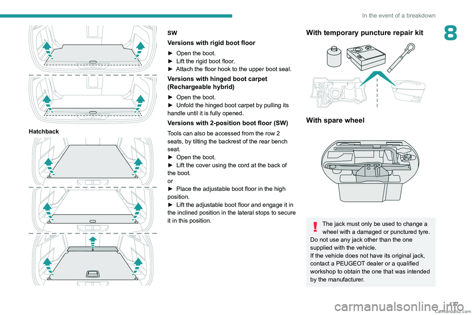
Versions with rigid boot floor
► Open the boot.
► Lift the rigid boot floor .
►
Attach the floor hook to the upper boot seal.
Versions with hinged boot carpet
(Rechargeable hybrid)
► Open the boot.
► Unfold the hinged boot carpet by pulling its
handle until it is fully opened.
Versions with 2-position boot floor (SW)
Tools can also be accessed from the row 2
seats, by tilting the backrest of the rear bench
seat.
►
Open the boot.
►
Lift the cover using the cord at the back of
the boot.
or
►
Place the adjustable boot floor in the high
position.
►
Lift the adjustable boot floor and engage it in
the inclined position in the lateral stops to secure
it in this position.
With temporary puncture repair kit
With spare wheel
The jack must only be used to change a wheel with a damaged or punctured tyre.
Do not use any jack other than the one
supplied with the vehicle.
If the vehicle does not have its original jack,
contact a PEUGEOT dealer or a qualified
workshop to obtain the one that was intended
by the manufacturer. CarM an uals 2 .c o m
Page 180 of 260
178
In the event of a breakdown
The jack meets European standards, as
defined in the Machinery Directive 2006/42/
CE.
The jack does not require any maintenance.
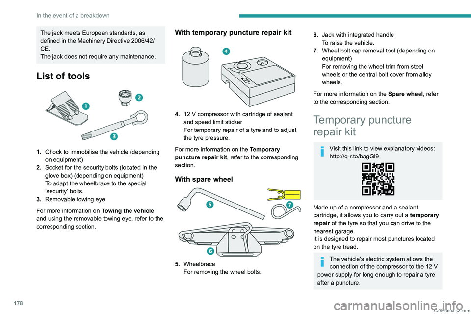
List of tools
1.Chock to immobilise the vehicle (depending
on equipment)
2. Socket for the security bolts (located in the
glove box) (depending on equipment)
To adapt the wheelbrace to the special
‘security’ bolts.
3. Removable towing eye
For more information on Towing the vehicle
and using the removable towing eye, refer to the
corresponding section.
With temporary puncture repair kit
4. 12 V compressor with cartridge of sealant
and speed limit sticker
For temporary repair of a tyre and to adjust
the tyre pressure.
For more information on the Temporary
puncture repair kit, refer to the corresponding
section.
With spare wheel
5. Wheelbrace
For removing the wheel bolts.
6.Jack with integrated handle
To raise the vehicle.
7. Wheel bolt cap removal tool (depending on
equipment)
For removing the wheel trim from steel
wheels or the central bolt cover from alloy
wheels.
For more information on the Spare wheel, refer
to the corresponding section.
Temporary puncture repair kit
Visit this link to view explanatory videos:
http://q-r.to/bagGl9
Made up of a compressor and a sealant
cartridge,
it allows you to carry out a temporary
repair of the tyre so that you can drive to the
nearest garage.
It is designed to repair most punctures located
on the tyre tread.
The vehicle's electric system allows the connection of the compressor to the 12 V
power supply for long enough to repair a tyre
after a puncture. CarM an uals 2 .c o m
Page 184 of 260
182
In the event of a breakdown
Hatchback
SW
► T ighten the central nut sufficiently to retain
the wheel correctly.
►
Put the tool box back in place in the middle of
the wheel and clip it in place.
Removing a wheel
Parking the vehicle
Immobilise the vehicle where it does
not obstruct traffic: the ground must be level,
stable and non-slippery.
With a manual gearbox, engage first gear
to lock the wheels, apply the parking brake,
unless it is set to automatic mode, and switch
off the ignition.
With an automatic gearbox, select mode
P
to lock the wheels, apply the parking brake,
unless it is set to automatic mode, and switch
off the ignition.
Check that the parking brake indicator lamps
on the instrument panel are on fixed.
The occupants must get out of the vehicle
and wait where they are safe.
If necessary, place a chock under the wheel
diagonally opposite the wheel to be changed.
Never go underneath a vehicle raised using a
jack; use an axle stand.
Wheel with wheel trim
When removing the wheel , first remove
the wheel trim by pulling at the valve aperture
using the wheelbrace.
When refitting the wheel , refit the wheel
trim, starting by placing its aperture in line
with the valve and then pushing it into place
all round its edge with the palm of your hand.
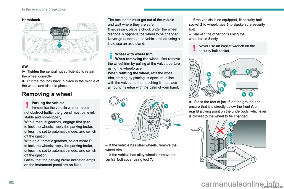
– If the vehicle has steel wheels, remove the
wheel trim.
–
If the vehicle has alloy wheels, remove the
central bolt cover using tool 7
.
– If the vehicle is so equipped, fit security bolt
socket 2 to wheelbrace 5 to slacken the security
bolt.
–
Slacken the other bolts using the
wheelbrace
5
only.
Never use an impact wrench on the
security bolt socket.
► Place the foot of jack 6 on the ground and
ensure that it is directly below the front A or
rear
B jacking point on the underbody, whichever
is closest to the wheel to be changed.
CarM an uals 2 .c o m