2023 PEUGEOT 3008 boot
[x] Cancel search: bootPage 178 of 292
176
Practical information
During charging
As a safety measure, the engine will
not start if the charging cable is plugged into
the connector on the vehicle. A warning is
displayed on the instrument panel.
While charging is in progress, unlocking the
vehicle will cause the charging to stop.
If no action is taken on one of the openings
(door or boot) or on the charging nozzle, the
vehicle will lock again after 30 seconds and
charging will resume automatically.
Never work under the bonnet:
–
Some areas remain very hot, even an hour
after charging ends - risk of burns!
–
The fan may start at any time - risk of cuts
or strangulation!
After charging
Check that the charging flap is closed.
Do not leave the cable connected to the
domestic power socket - risk of short-circuit
or electrocution in the event of contact with or
immersion in water!
Charging procedure
Connection
► Before charging, check that the gear selector
is in mode P and the ignition is off, otherwise
charging is impossible. ►
Press on the rear of the charging flap to open
it and check that there are no foreign bodies on
the vehicle's charging connector
.
The light guides in the flap come on white.
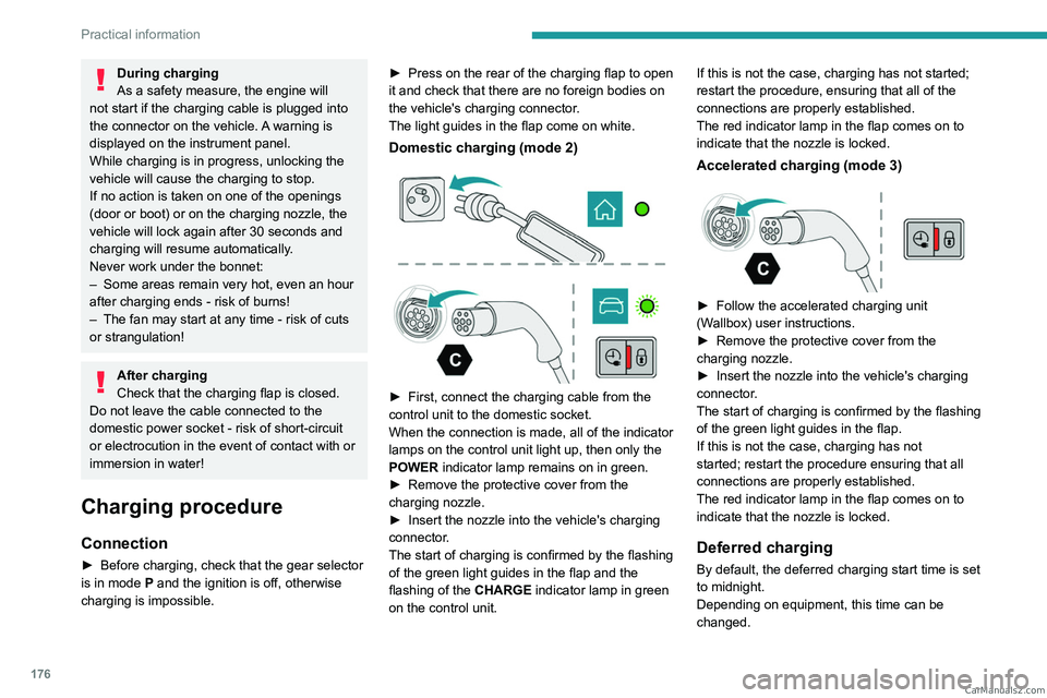
Domestic charging (mode 2)
► First, connect the charging cable from the
control unit to the domestic socket.
When the connection is made, all of the indicator
lamps on the control unit light up, then only the
POWER
indicator lamp remains on in green.
►
Remove the protective cover from the
charging nozzle.
►
Insert the nozzle into the vehicle's charging
connector
.
The start of charging is confirmed by the flashing
of the green light guides in the flap and the
flashing of the
CHARGE indicator lamp in green
on the control unit. If this is not the case, charging has not started;
restart the procedure, ensuring that all of the
connections are properly established.
The red indicator lamp in the flap comes on to
indicate that the nozzle is locked.
Accelerated charging (mode 3)
► Follow the accelerated charging unit
(W allbox) user instructions.
►
Remove the protective cover from the
charging nozzle.
►
Insert the nozzle into the vehicle's charging
connector
.
The start of charging is confirmed by the flashing
of the green light guides in the flap.
If this is not the case, charging has not
started; restart the procedure ensuring that all
connections are properly established.
The red indicator lamp in the flap comes on to
indicate that the nozzle is locked.
Deferred charging
By default, the deferred charging start time is set
to midnight.
Depending on equipment, this time can be
changed. CarM an uals 2 .c o m
Page 180 of 292

178
Practical information
Comply with the maximum authorised
towable weight, as indicated on your
vehicle's registration certificate, on the
manufacturer's label and in the Technical
data section of this guide.
If using accessories attached to the
towing device (e.g. bicycle carriers, tow
boxes):
–
Comply with the maximum authorised nose
weight.
–
Do not transport more than 4 conventional
bicycles or 2 electric bicycles.
When loading bicycles onto a bicycle carrier
on a towball, be sure to place the heaviest
bicycles as close as possible to the vehicle.
Observe the legislation in force in the
country where you are driving.
Vehicle equipped with motorised
tailgate with hands-free function
(Hands-Free Tailgate Access)
To avoid unintentionally opening the
motorised tailgate when operating the towing
device:
–
Deactivate this function in advance in the
vehicle's configuration menu.
–
Or remove the electronic key from the
recognition zone, with the tailgate closed.
Towing device with quickly detachable towball
Presentation
No tools are required to install or remove this
genuine towing device.
1. Carrier
2. Protective plug
3. Connection socket
4. Safety eye
5. Detachable towball
6. Locking/unlocking wheel
7. Security key lock
8. Label to note the key references
A. Locked position (the green marks are
opposite each other); the wheel is in contact
with the towball (no gap).
B. Unlocked position (red mark opposite the green mark); the wheel is no longer
in contact with the towball (gap of around
5
mm).
Affix the enclosed label in a clearly visible location, close to the carrier or in the
boot.
Trailers with LED lamps are not compatible with the wiring harness of this
device.
To ensure complete safety while driving with a Towing device , refer to the
corresponding section. CarM an uals 2 .c o m
Page 198 of 292
196
In the event of a breakdown
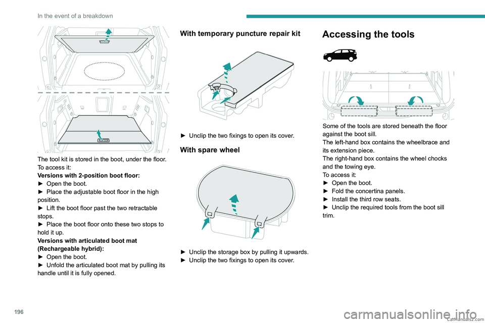
The tool kit is stored in the boot, under the floor.
To access it:
Versions with 2-position boot floor:
►
Open the boot.
►
Place the adjustable boot floor in the high
position.
►
Lift the boot floor past the two retractable
stops.
►
Place the boot floor onto these two stops to
hold it up.
V
ersions with articulated boot mat
(Rechargeable hybrid):
►
Open the boot.
►
Unfold the articulated boot mat by pulling its
handle until it is fully opened.
With temporary puncture repair kit
► Unclip the two fixings to open its cover .
With spare wheel
► Unclip the storage box by pulling it upwards.
► Unclip the two fixings to open its cover .
Accessing the tools
Some of the tools are stored beneath the floor
against the boot sill.
The left-hand box contains the wheelbrace and
its extension piece.
The right-hand box contains the wheel chocks
and the towing eye.
To access it:
►
Open the boot.
►
Fold the concertina panels.
►
Install the third row seats.
►
Unclip the required tools from the boot sill
trim. CarM an uals 2 .c o m
Page 203 of 292
201
In the event of a breakdown
8► Start the compressor by placing the switch at
position "I" and adjust the pressure to the value
shown on the vehicle's tyre pressure label. To
deflate: press the black button located on the
compressor pipe, near the valve connection.
If after 7 minutes the pressure of 2 bar is
not reached, the tyre is damaged;
contact a PEUGEOT
dealer or a qualified
workshop for assistance.
►
Once the correct pressure is reached, put the
switch in position
"O".
►
Remove the kit and stow it.
►
Refit the cap on the valve.
Spare wheel
Visit this link to view explanatory videos:
http://q-r.to/bagGl9
Accessing the spare wheel
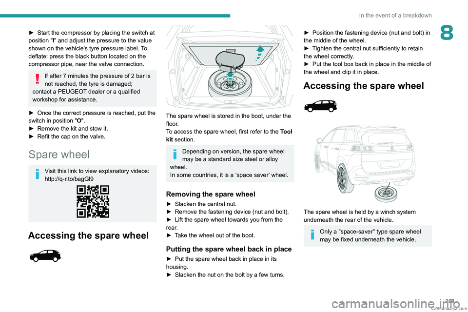
The spare wheel is stored in the boot, under the
floor.
To access the spare wheel, first refer to the Tool
kit
section.
Depending on version, the spare wheel
may be a standard size steel or alloy
wheel.
In some countries, it is a ‘space saver’ wheel.
Removing the spare wheel
► Slacken the central nut.
► Remove the fastening device (nut and bolt).
►
Lift the spare wheel towards you from the
rear
.
►
T
ake the wheel out of the boot.
Putting the spare wheel back in place
► Put the spare wheel back in place in its
housing.
►
Slacken the nut on the bolt by a few turns.
► Position the fastening device (nut and bolt) in
the middle of the wheel.
►
T
ighten the central nut sufficiently to retain
the wheel correctly.
►
Put the tool box back in place in the middle of
the wheel and clip it in place.
Accessing the spare wheel
The spare wheel is held by a winch system
underneath the rear of the vehicle.
Only a "space-saver" type spare wheel
may be fixed underneath the vehicle. CarM an uals 2 .c o m
Page 204 of 292
202
In the event of a breakdown
Removing the spare wheel
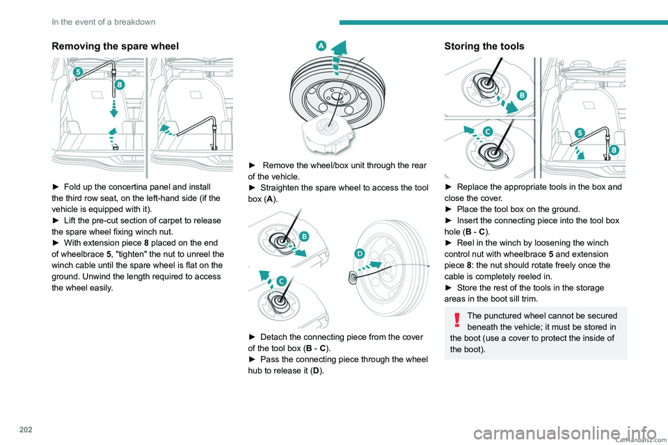
► Fold up the concertina panel and install
the third row seat, on the left-hand side (if the
vehicle is equipped with it).
►
Lift the pre-cut section of carpet to release
the spare wheel
fixing winch nut.
►
With extension piece 8
placed on the end
of wheelbrace 5, "tighten" the nut to unreel the
winch cable until the spare wheel is flat on the
ground. Unwind the length required to access
the wheel easily.
► Remove the wheel/box unit through the rear
of the vehicle.
►
Straighten the spare wheel to access the tool
box (
A).
► Detach the connecting piece from the cover
of the tool box ( B - C).
►
Pass the connecting piece through the wheel
hub to release it ( D
).
Storing the tools
► Replace the appropriate tools in the box and
close the cover .
►
Place the tool box on the ground.
►
Insert the connecting piece into the tool box
hole (
B - C).
►
Reel in the winch by loosening the winch
control nut with wheelbrace 5
and extension
piece 8: the nut should rotate freely once the
cable is completely reeled in.
►
Store the rest of the tools in the storage
areas in the boot sill trim.
The punctured wheel cannot be secured beneath the vehicle; it must be stored in
the boot (use a cover to protect the inside of
the boot). CarM an uals 2 .c o m
Page 207 of 292
205
In the event of a breakdown
8
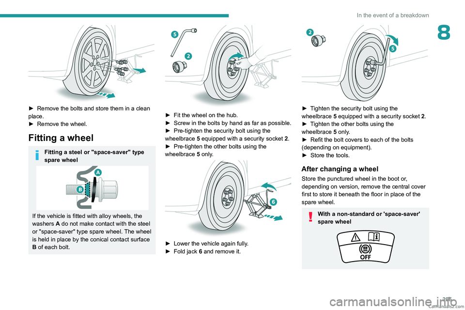
► Remove the bolts and store them in a clean
place.
►
Remove the wheel.
Fitting a wheel
Fitting a steel or "space-saver" type
spare wheel
If the vehicle is fitted with alloy wheels, the
washers A do not make contact with the steel
or "space-saver" type spare wheel. The wheel
is held in place by the conical contact surface
B of each bolt.
► Fit the wheel on the hub.
► Screw in the bolts by hand as far as possible.
►
Pre-tighten the security bolt using the
wheelbrace
5
equipped with a security socket
2
.
►
Pre-tighten the other bolts using the
wheelbrace
5
only.
► Lower the vehicle again fully .
► Fold jack 6 and remove it.
► Tighten the security bolt using the
wheelbrace 5 equipped with a security socket 2 .
►
T
ighten the other bolts using the
wheelbrace
5
only.
►
Refit the bolt covers to each of the bolts
(depending on equipment).
►
Store the tools.
After changing a wheel
Store the punctured wheel in the boot or,
depending on version, remove the central cover
first to store it beneath the floor in place of the
spare wheel.
With a non-standard or 'space-saver'
spare wheel CarM an uals 2 .c o m
Page 212 of 292
210
In the event of a breakdown
– When using the vehicle mainly for short
journeys.
–
If the vehicle is to be taken off the road for
several weeks.
Consult a PEUGEOT
dealer or a qualified
workshop.
To charge the vehicle's battery yourself, use only a charger compatible with
lead-acid batteries with a nominal voltage of
12
V.
Follow the instructions provided by the
manufacturer of the charger.
Never reverse polarities.
It is not necessary to disconnect the
battery.
►
Switch the ignition off.
►
Switch off all electrical consumers (audio
system, lighting, wipers, etc.).
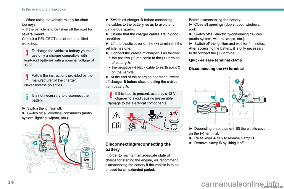
► Switch off charger B before connecting
the cables to the battery, so as to avoid any
dangerous sparks.
►
Ensure that the charger cables are in good
condition.
►
Lift the plastic cover on the (+) terminal, if the
vehicle has one.
►
Connect the cables of charger B
as follows:
•
the positive (+) red cable to the (+) terminal
of battery
A,
•
the negative (-) black cable to earth point C
on the vehicle.
►
At the end of the charging operation, switch
off charger B
before disconnecting the cables
from battery A.
If this label is present, use only a 12 V
charger to avoid causing irreversible
damage to the electrical components.
24V
12V
Disconnecting/reconnecting the
battery
In order to maintain an adequate state of
charge for starting the engine, we recommend
disconnecting the battery if the vehicle is to be
unused for an extended period. Before disconnecting the battery:
►
Close all openings (doors, boot, windows,
roof).
►
Switch off all electricity-consuming devices
(audio system, wipers, lamps, etc.).
►
Switch off the ignition and wait for 4
minutes.
After accessing the battery, it is only necessary
to disconnect the (+) terminal.
Quick-release terminal clamp
Disconnecting the (+) terminal
► Depending on equipment, lift the plastic cover
on the (+) terminal.
►
Raise lever
A
fully to release clamp
B
.
►
Remove clamp
B
by lifting it off. CarM an uals 2 .c o m
Page 213 of 292
2 11
In the event of a breakdown
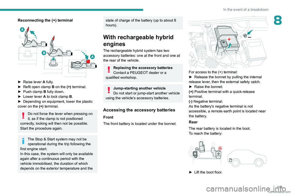
8Reconnecting the (+) terminal
► Raise lever A fully.
► Refit open clamp B on the (+) terminal.
►
Push clamp
B fully down.
►
Lower lever
A
to lock clamp B.
►
Depending on equipment, lower the plastic
cover on the
(+) terminal.
Do not force the lever when pressing on
it, as if the clamp is not positioned
correctly, locking will then not be possible.
Start the procedure again.
The Stop & Start system may not be operational during the trip following the
first engine start.
In this case, the system will only be available
again after a continuous period with the
vehicle immobilised, the duration of which
depends on the exterior temperature and the
state of charge of the battery (up to about 8
hours).
With rechargeable hybrid
engines
The rechargeable hybrid system has two accessory batteries: one at the front and one at
the rear of the vehicle.
Replacing the accessory batteries
Contact a PEUGEOT dealer or a
qualified workshop.
Jump-starting another vehicle
Do not start or jump-start another vehicle
using the vehicle’s accessory batteries.
Accessing the accessory batteries
Front
The front battery is located under the bonnet.
For access to the (+) terminal:
► Release the bonnet by pulling the internal
release lever
, then the external safety catch.
►
Raise the bonnet.
(+)
Positive terminal with a quick-release
terminal.
(-) Negative terminal.
As the battery's negative terminal is not
accessible, a remote earth point is located near
the battery.
Rear
The rear battery is located in the boot.
To reach the battery:
► Lift the boot floor . CarM an uals 2 .c o m