2023 PEUGEOT 3008 bonnet
[x] Cancel search: bonnetPage 178 of 292
176
Practical information
During charging
As a safety measure, the engine will
not start if the charging cable is plugged into
the connector on the vehicle. A warning is
displayed on the instrument panel.
While charging is in progress, unlocking the
vehicle will cause the charging to stop.
If no action is taken on one of the openings
(door or boot) or on the charging nozzle, the
vehicle will lock again after 30 seconds and
charging will resume automatically.
Never work under the bonnet:
–
Some areas remain very hot, even an hour
after charging ends - risk of burns!
–
The fan may start at any time - risk of cuts
or strangulation!
After charging
Check that the charging flap is closed.
Do not leave the cable connected to the
domestic power socket - risk of short-circuit
or electrocution in the event of contact with or
immersion in water!
Charging procedure
Connection
► Before charging, check that the gear selector
is in mode P and the ignition is off, otherwise
charging is impossible. ►
Press on the rear of the charging flap to open
it and check that there are no foreign bodies on
the vehicle's charging connector
.
The light guides in the flap come on white.
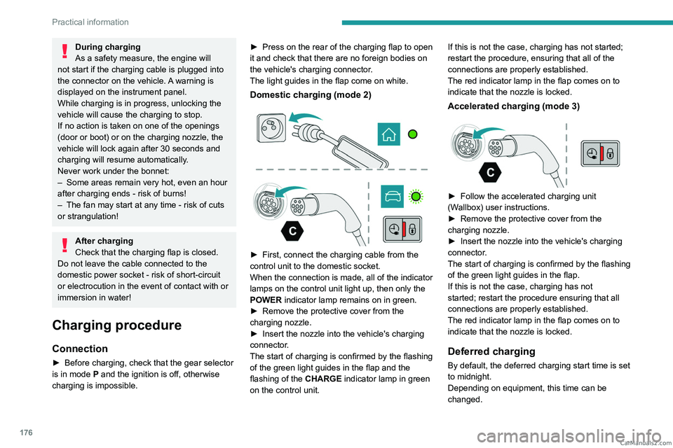
Domestic charging (mode 2)
► First, connect the charging cable from the
control unit to the domestic socket.
When the connection is made, all of the indicator
lamps on the control unit light up, then only the
POWER
indicator lamp remains on in green.
►
Remove the protective cover from the
charging nozzle.
►
Insert the nozzle into the vehicle's charging
connector
.
The start of charging is confirmed by the flashing
of the green light guides in the flap and the
flashing of the
CHARGE indicator lamp in green
on the control unit. If this is not the case, charging has not started;
restart the procedure, ensuring that all of the
connections are properly established.
The red indicator lamp in the flap comes on to
indicate that the nozzle is locked.
Accelerated charging (mode 3)
► Follow the accelerated charging unit
(W allbox) user instructions.
►
Remove the protective cover from the
charging nozzle.
►
Insert the nozzle into the vehicle's charging
connector
.
The start of charging is confirmed by the flashing
of the green light guides in the flap.
If this is not the case, charging has not
started; restart the procedure ensuring that all
connections are properly established.
The red indicator lamp in the flap comes on to
indicate that the nozzle is locked.
Deferred charging
By default, the deferred charging start time is set
to midnight.
Depending on equipment, this time can be
changed. CarM an uals 2 .c o m
Page 185 of 292
183
Practical information
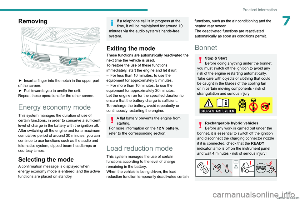
7Removing
► Insert a finger into the notch in the upper part
of the screen.
►
Pull towards you to unclip the unit.
Repeat these operations for the other screen.
Energy economy mode
This system manages the duration of use of
certain functions, in order to conserve a sufficient
level of charge in the battery with the ignition off.
After switching off the engine and for a maximum
cumulative period of around 30 minutes, you can
continue to use functions such as the audio and
telematics system, dipped beam headlamps or
courtesy lamps.
Selecting the mode
A confirmation message is displayed when
energy economy mode is entered, and the active
functions are placed on standby.
If a telephone call is in progress at the
time, it will be maintained for around 10
minutes via the audio system’s hands-free
system.
Exiting the mode
These functions are automatically reactivated the
next time the vehicle is used.
To restore the use of these functions
immediately, start the engine and let it run:
–
For less than 10 minutes, to use the
equipment for approximately 5 minutes.
–
For more than 10 minutes, to use the
equipment for approximately 30 minutes.
Let the engine run for the specified duration to
ensure that the battery charge is sufficient.
T
o recharge the battery, avoid repeatedly or
continuously restarting the engine.
A flat battery prevents the engine from starting.
For more information on the 12
V battery,
refer to the corresponding section.
Load reduction mode
This system manages the use of certain
functions according to the level of charge
remaining in the battery.
When the vehicle is being driven, the load
reduction function temporarily deactivates certain
functions, such as the air conditioning and the
heated rear screen.
The deactivated functions are reactivated
automatically as soon as conditions permit.
Bonnet
Stop & Start
Before doing anything under the bonnet,
you must switch off the ignition to avoid any
risk of the engine restarting automatically.
Take care with objects or clothing that could
be caught in the blades of the cooling fan
or in certain moving components - risk of
strangulation and serious injury!
Rechargeable hybrid vehicles
Before any work is carried out under the
bonnet, it is essential to switch off the ignition
and disconnect the charging connector nozzle
if it is connected, check that the READY
indicator lamp is off on the instrument panel
and wait 4 minutes - risk of serious injury! CarM an uals 2 .c o m
Page 186 of 292
184
Practical information
The location of the interior bonnet release lever prevents the bonnet being
opened when the left-hand front door is
closed.
When the engine is hot, handle the
exterior safety catch and the bonnet stay
with care (risk of burns), using the protected
area.
When the bonnet is open, take care not to
damage the safety catch.
Do not open the bonnet under very windy
conditions.
Cooling of the engine when stopped
The engine cooling fan may start after
the engine has been switched off.
Take care with objects or clothing that
could be caught in the blades of the fan!
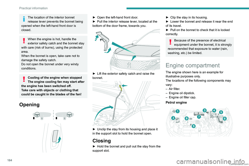
Opening
► Open the left-hand front door .
► Pull the interior release lever , located at the
bottom of the door frame, towards you.
► Lift the exterior safety catch and raise the
bonnet.
► Unclip the stay from its housing and place it
in the support slot to hold the bonnet open.
Closing
► Hold the bonnet and pull out the stay from the
support slot.
► Clip the stay in its housing.
► Lower the bonnet and release it near the end
of its travel.
►
Pull on the bonnet to check that it is locked
correctly
.
Because of the presence of electrical
equipment under the bonnet, it is strongly
recommended that exposure to water (rain,
washing, etc.) be limited.
Engine compartment
The engine shown here is an example for
illustrative purposes only.
The locations of the following components may
vary:
–
Air filter
.
–
Engine oil dipstick.
–
Engine oil filler cap.
Petrol engine
CarM an uals 2 .c o m
Page 187 of 292

185
Practical information
7Diesel engine
1.Screenwash fluid reservoir
2. Engine coolant reservoir
3. Brake fluid reservoir
4. Battery/Fuses
5. Remote earth point (-)
6. Fusebox
7. Air filter
8. Engine oil filler cap
9. Engine oil dipstick
Diesel fuel system
This system is under very high pressure.
All work must be carried out only by a
PEUGEOT dealer or a qualified workshop
Checking levels
Check all of the following levels regularly in
accordance with the Manufacturer's service
schedule. Top them up if required, unless
otherwise indicated.
If a level drops significantly, have the
corresponding system checked by a PEUGEOT
dealer or a qualified workshop.
The fluids must comply with the Manufacturer's requirements and with
the vehicle's engine.
Take care when working under the bonnet, as certain areas of the engine
may be extremely hot (risk of burns) and the
cooling fan could start at any time (even with
the ignition off).
Used products
Avoid prolonged contact of used oil or fluids with the skin.
Most of these fluids are harmful to health and
very corrosive.
Do not discard used oil or fluids into
sewers or onto the ground.
Empty used oil into the containers reserved
for this purpose at a PEUGEOT dealer or a
qualified workshop.
Engine oil
The level is checked, with the engine having been switched off for at least 30
minutes and on level ground, either using the oil
level indicator in the instrument panel when the
ignition is switched on (for vehicles equipped
with an electric gauge), or using the dipstick.
It is normal to top up the oil level between two
services (or oil changes). It is recommended
that you check the level, and top up if necessary,
every 3,000 miles (5,000 km).
In order to maintain the reliability of the
engine and emissions control system,
never use additives in the engine oil.
Checking using the dipstick
For the location of the dipstick, please refer
to the illustration of the corresponding engine
compartment.
►
Grasp the dipstick by its coloured grip and
pull it out completely
.
►
Wipe the end of the dipstick using a clean,
lint-free cloth.
► Reinsert the dipstick and push fully down,
then pull it out again to visually check the oil
level: the correct level is between marks A
(max)
and B (min).
Do not start the engine if the level is:
–
above mark
A: contact a PEUGEOT dealer or
a qualified workshop. CarM an uals 2 .c o m
Page 211 of 292
209
In the event of a breakdown
8Accessing the battery
The battery is located under the bonnet.
For access to the (+) terminal:
► Release the bonnet by pulling the internal
release lever
, then the external safety catch.
►
Raise the bonnet.
(+)
Positive terminal with a quick-release
terminal.
(-) Negative terminal.
As the battery's negative terminal is not
accessible, a remote earth point is located near
the battery.
Starting using another battery
If the vehicle's battery is flat, the engine can be
started using a backup battery (either external or
from another vehicle) and jump leads or using a
battery booster.
Never start the engine by connecting a
battery charger.
Never use a 24
V or higher battery booster.
Check beforehand that the backup battery
has a nominal voltage of 12 V and a capacity
at least equal to that of the discharged
battery.
The two vehicles must not be in contact with
each other.
Switch off all electricity-consuming equipment
on both vehicles (audio system, wipers,
lighting, etc.).
Make sure that the jump leads are well away
from the engine’s moving parts (fan, belt,
etc.).
Do not disconnect the (+) terminal while the
engine is running.
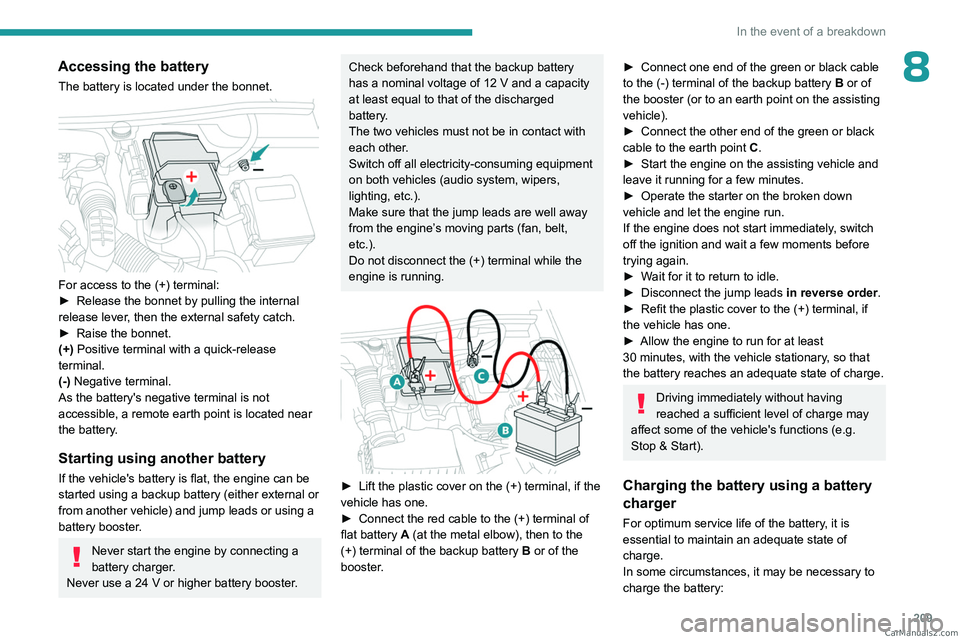
► Lift the plastic cover on the (+) terminal, if the
vehicle has one.
►
Connect the red cable to the (+) terminal of
flat battery
A (at the metal elbow), then to the
(+) terminal of the backup battery
B or of the
booster.
► Connect one end of the green or black cable
to the (-) terminal of the backup battery B or of
the booster (or to an earth point on the assisting
vehicle).
►
Connect the other end of the green or black
cable to the earth point
C
.
►
Start the engine on the assisting vehicle and
leave it running for a few minutes.
►
Operate the starter on the broken down
vehicle and let the engine run.
If the engine does not start immediately
, switch
off the ignition and wait a few moments before
trying again.
►
W
ait for it to return to idle.
►
Disconnect the jump leads in reverse order.
►
Refit the plastic cover to the (+) terminal, if
the vehicle has one.
►
Allow the engine to run for at least
30
minutes, with the vehicle stationary, so that
the battery reaches an adequate state of charge.
Driving immediately without having
reached a sufficient level of charge may
affect some of the vehicle's functions (e.g.
Stop & Start).
Charging the battery using a battery
charger
For optimum service life of the battery, it is
essential to maintain an adequate state of
charge.
In some circumstances, it may be necessary to
charge the battery: CarM an uals 2 .c o m
Page 213 of 292
2 11
In the event of a breakdown
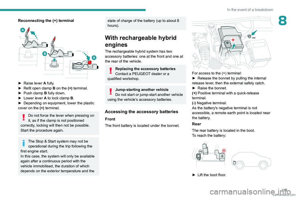
8Reconnecting the (+) terminal
► Raise lever A fully.
► Refit open clamp B on the (+) terminal.
►
Push clamp
B fully down.
►
Lower lever
A
to lock clamp B.
►
Depending on equipment, lower the plastic
cover on the
(+) terminal.
Do not force the lever when pressing on
it, as if the clamp is not positioned
correctly, locking will then not be possible.
Start the procedure again.
The Stop & Start system may not be operational during the trip following the
first engine start.
In this case, the system will only be available
again after a continuous period with the
vehicle immobilised, the duration of which
depends on the exterior temperature and the
state of charge of the battery (up to about 8
hours).
With rechargeable hybrid
engines
The rechargeable hybrid system has two accessory batteries: one at the front and one at
the rear of the vehicle.
Replacing the accessory batteries
Contact a PEUGEOT dealer or a
qualified workshop.
Jump-starting another vehicle
Do not start or jump-start another vehicle
using the vehicle’s accessory batteries.
Accessing the accessory batteries
Front
The front battery is located under the bonnet.
For access to the (+) terminal:
► Release the bonnet by pulling the internal
release lever
, then the external safety catch.
►
Raise the bonnet.
(+)
Positive terminal with a quick-release
terminal.
(-) Negative terminal.
As the battery's negative terminal is not
accessible, a remote earth point is located near
the battery.
Rear
The rear battery is located in the boot.
To reach the battery:
► Lift the boot floor . CarM an uals 2 .c o m
Page 225 of 292
223
Technical data
9
Identification markings
Various visible markings for vehicle identification
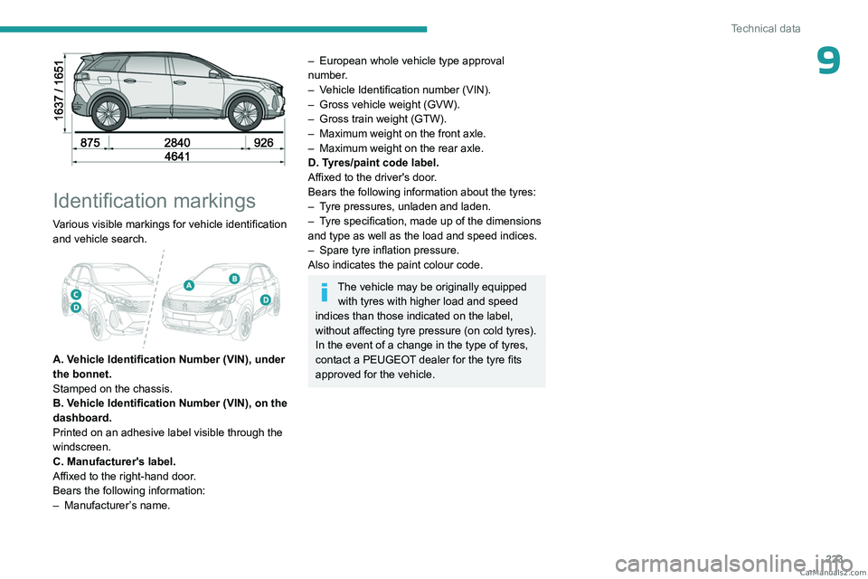
and vehicle search.
A. Vehicle Identification Number (VIN), under
the bonnet.
Stamped on the chassis.
B. Vehicle Identification Number (VIN), on the
dashboard.
Printed on an adhesive label visible through the
windscreen.
C. Manufacturer's label.
Affixed to the right-hand door.
Bears the following information:
–
Manufacturer
’s name.
– European whole vehicle type approval
number .
–
V
ehicle Identification number (VIN).
–
Gross vehicle weight (GVW).
–
Gross train weight (GTW).
–
Maximum weight on the front axle.
–
Maximum weight on the rear axle.
D. T
yres/paint code label.
Affixed to the driver's door.
Bears the following information about the tyres:
–
T
yre pressures, unladen and laden.
–
T
yre specification, made up of the dimensions
and type as well as the load and speed indices.
–
Spare tyre inflation pressure.
Also indicates the paint colour code.
The vehicle may be originally equipped with tyres with higher load and speed
indices than those indicated on the label,
without affecting tyre pressure (on cold tyres).
In the event of a change in the type of tyres,
contact a PEUGEOT dealer for the tyre fits
approved for the vehicle. CarM an uals 2 .c o m
Page 267 of 292
265
Alphabetical index
A
ABS 87
Accelerated charging unit (Wallbox)
169–170
Accessories
84
Active Safety Brake
150–152
AdBlue®
18, 189
AdBlue® tank
190
Additive, Diesel
186–187
Adjusting headlamps
76
Adjusting head restraints
44
Adjusting seat
43, 45, 50–52
Adjusting the air distribution
58–60
Adjusting the air flow
58–60
Adjusting the date
235, 257
Adjusting the headlamp beam height
76
Adjusting the height and reach of
the steering wheel
47
Adjusting the lumbar support
43, 45
Adjusting the seat belt height
92
Adjusting the temperature
58
Adjusting the time
234, 258
Advanced Grip Control
89
Advice on care and maintenance
168, 192
Advice on driving
7, 111–112
Airbags
95, 97, 99
Airbags, curtain
96–97
Airbags, front
96–97, 100
Airbags, lateral
96–97
Air conditioning
56, 59
Air conditioning, automatic
60
Air conditioning, dual-zone
57
Air conditioning, dual-zone automatic
57
Air intake 58, 60
Air vents
56
Alarm
37–38
Amplifier, audio
63
Anti-lock braking system (ABS)
87
Antitheft / Immobiliser
27
Applications
249
Armrest, front
65
Armrest, rear
67
Assistance call
85–86
Assistance, emergency braking
87, 152
Audio streaming (Bluetooth)
230, 253
B
Backrest, folding 44
Battery, 12 V
183, 187, 208–212
Battery, ancillaries
208
Battery, charging
208–209, 212
Battery, remote control
31
Blanking screen (snow shield)
182
Blind
39–41
Blind spot monitoring
154
Blinds, side
68
BlueHDi
18, 20, 187, 195
Bluetooth (hands-free)
232, 254
Bluetooth (telephone)
232–233, 254–255
Bodywork
193
Bonnet
184
Boot
32–33, 36, 73
Boot (fittings)
68
Brake discs
188
Brake lamps 207
Brakes
188
Braking
123
Braking assistance system
87
Braking, automatic emergency
150–152
Braking, dynamic emergency
115–117
Brightness
234
Bulbs (changing)
206–207
C
Cable, audio 252
Cable, Jack
252
Capacity, fuel tank
165
Care of the bodywork
193
Central locking
29–30
Changing a bulb
206–207
Changing a fuse
208
Changing a wheel
195–197, 201–203
Changing a wiper blade
82–83
Changing the remote control battery
31
Changing to free-wheeling
191
Charge level indicator (Rechargeable
hybrid)
20
Charger, induction
64
Charger, wireless
64
Charging cable
171
Charging cable (Rechargeable
hybrid)
169–170, 176
Charging connector (Rechargeable
hybrid)
168, 175–177 CarM an uals 2 .c o m